For the given combination of gates shown in Fig., find the values of output y1 and y2 in the table given below Fig. Identify the gates I and II. 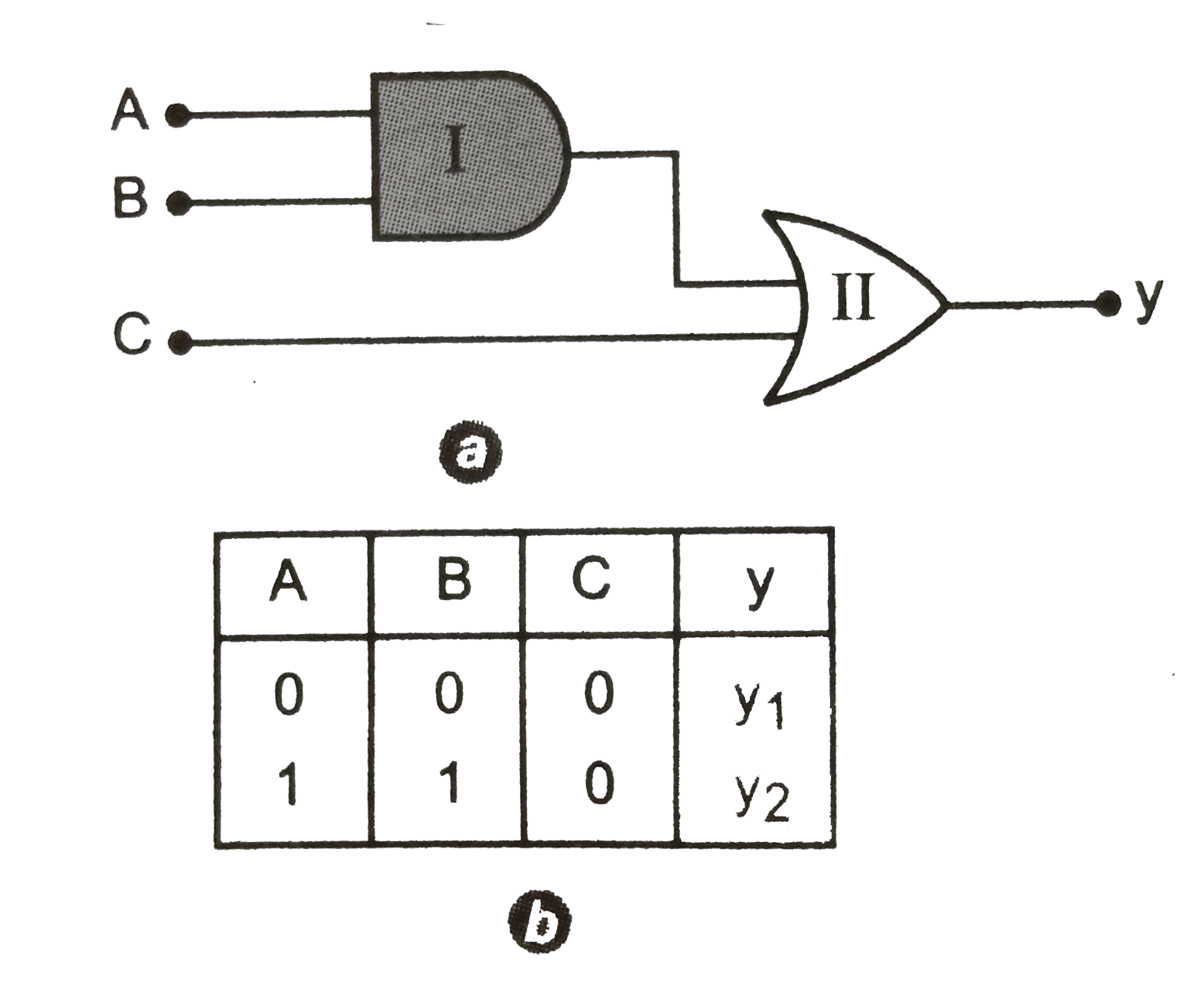
Video Solution
Text Solution
Gate I is AND gate and Gate II is OR gate.
Output of gate I is y′=A.B
Output of gate II is y=y′+C=(A.B)+C
When A=0,B=0,C=0,
then y1=(0.0)+0=0
When A=1,B=1,C=0,
then y2=(1.1)+0=1
|
Topper's Solved these Questions
- ELECTRONIC DEVICESBook:PRADEEPChapter:ELECTRONIC DEVICESExercise:SAMPLE PROBLEM
Explore 2 Videos
- ELECTRONIC DEVICESBook:PRADEEPChapter:ELECTRONIC DEVICESExercise:CONCEPTUAL PROBLEMS
Explore 1 Video
- ELECTROMAGNETIC WAVESBook:PRADEEPChapter:ELECTROMAGNETIC WAVESExercise:II Focus multiple choice question
Explore 5 Videos
- ELECTROSTATICSBook:PRADEEPChapter:ELECTROSTATICSExercise:ASSERTION-REASON TYPE QUESTIONS
Explore 2 Videos
Similar Questions
Knowledge Check
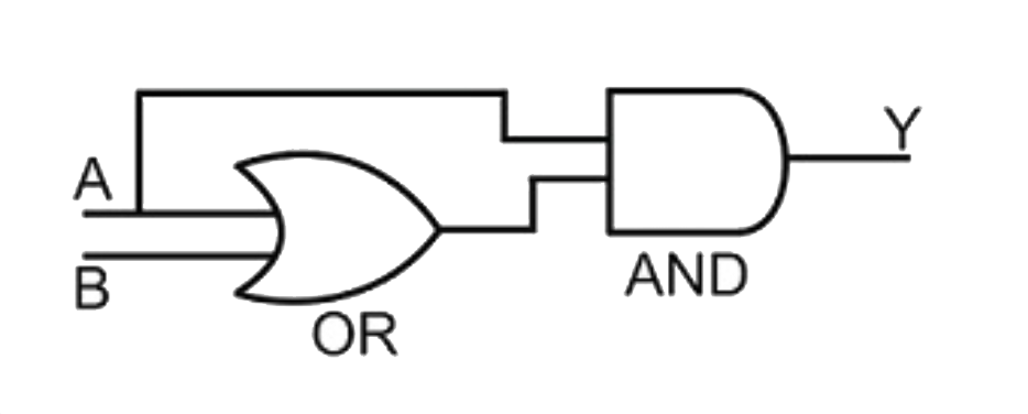
The output Y of the combination of gates shown in equal to :-
_E01_419_Q01.png) AAB¯¯¯ACA+BDAB
AAB¯¯¯ACA+BDAB_2019_CBT4_E01_066_Q01.png)
The output of the given combination of gates is equivalent to:ANANDBORCANDDNORThe output of the combination of the gates shown in the figure below is
 .AA+A.BB(A+B)A+¯¯¯BC(A.B)+(¯¯¯A.¯¯¯B)D(A+B)(¯¯¯¯¯¯¯¯A.B)
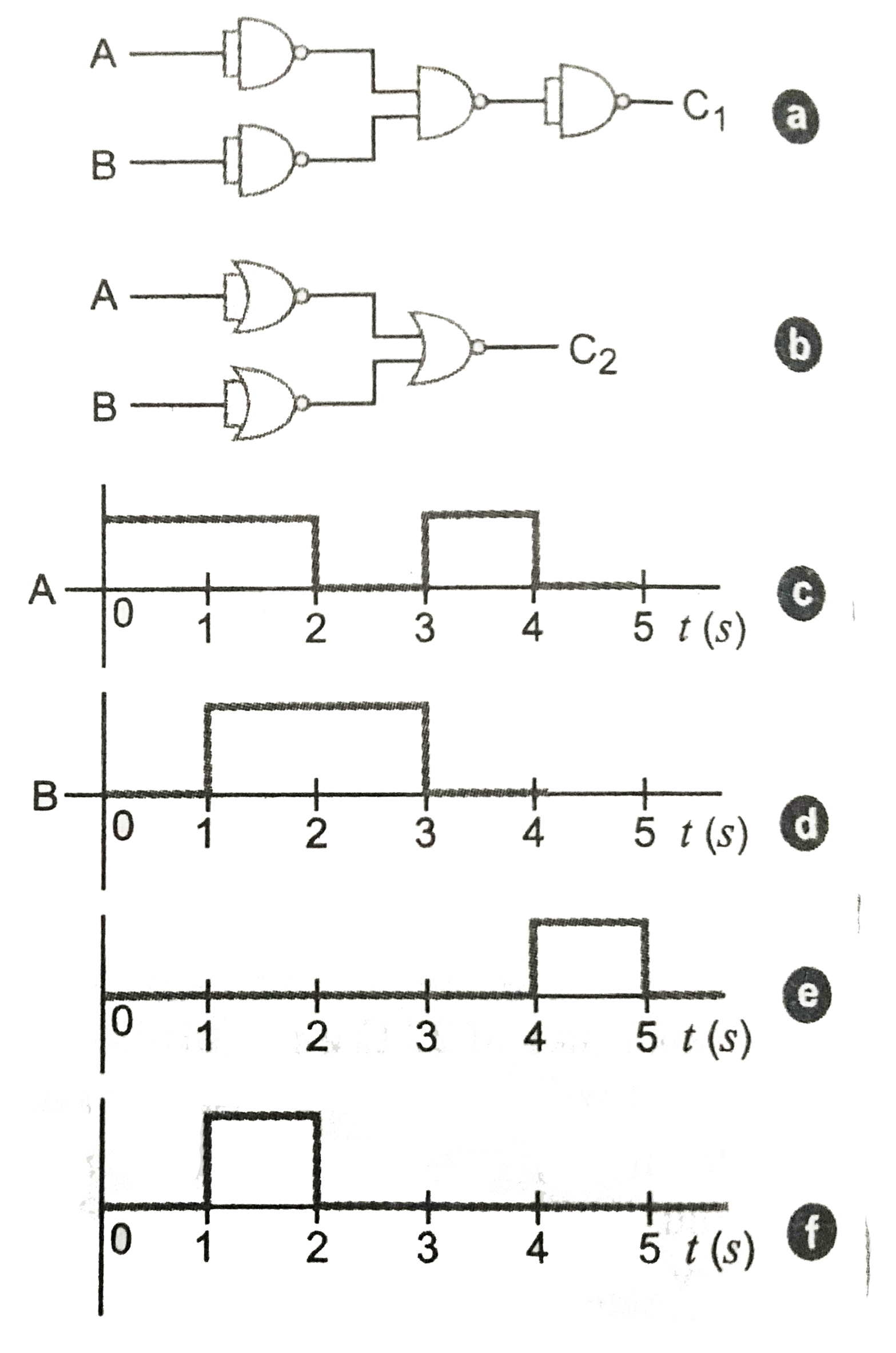
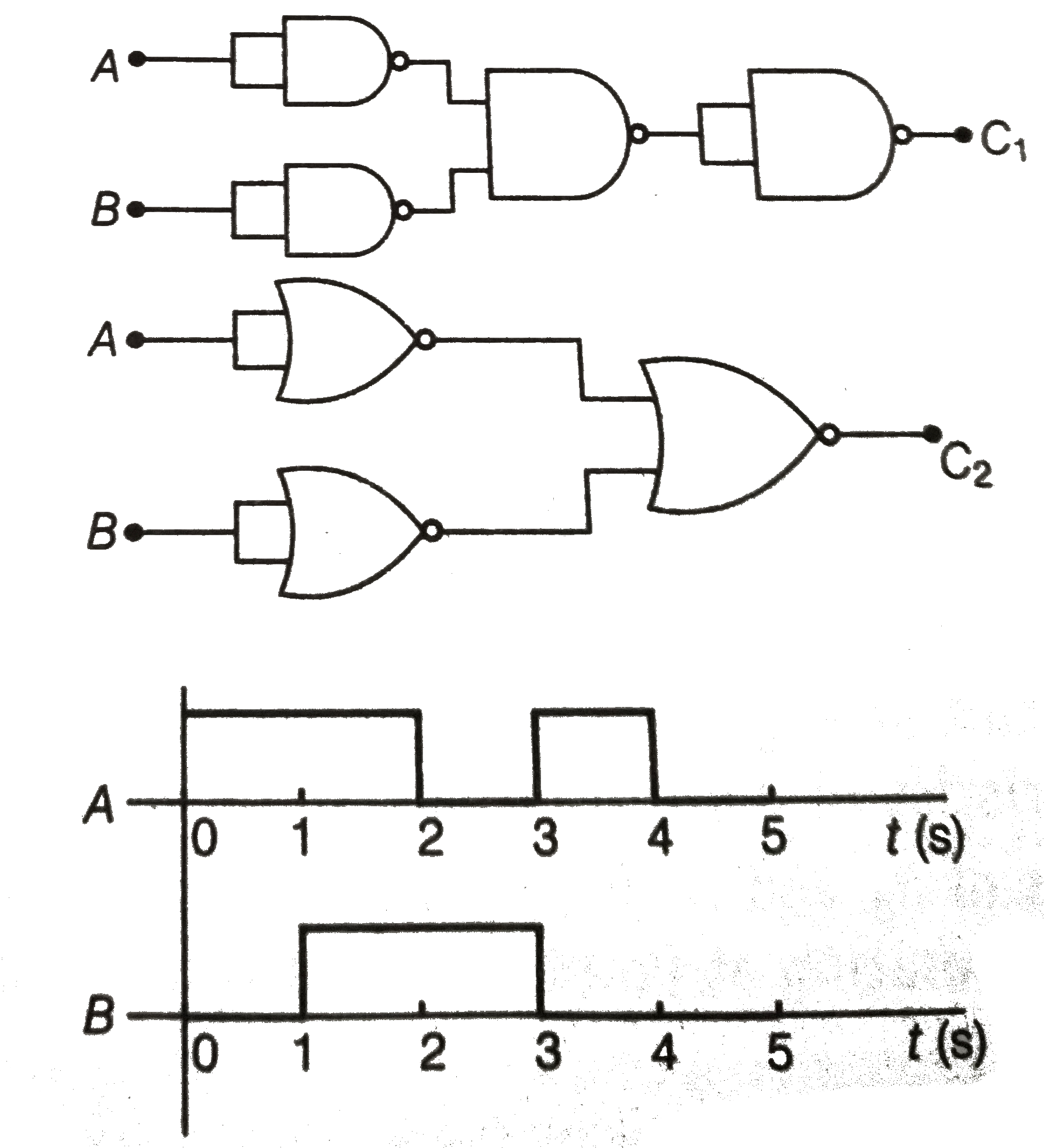
Draw the output signal C1 and C2 in the given combination of gates (Fig.)
View SolutionThe output Y of the combination of logic gates shown is equal to
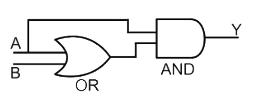
View SolutionThe output Y of the combination of logic gates shown is equal to
View SolutionDraw the output signals C1 and C2 in the given combination of gates.
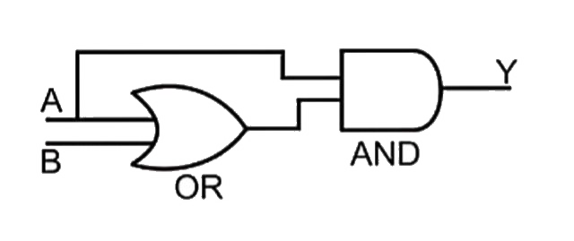
View SolutionThe output Y of the combination of logic gates shown is equal to
View Solution


