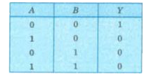
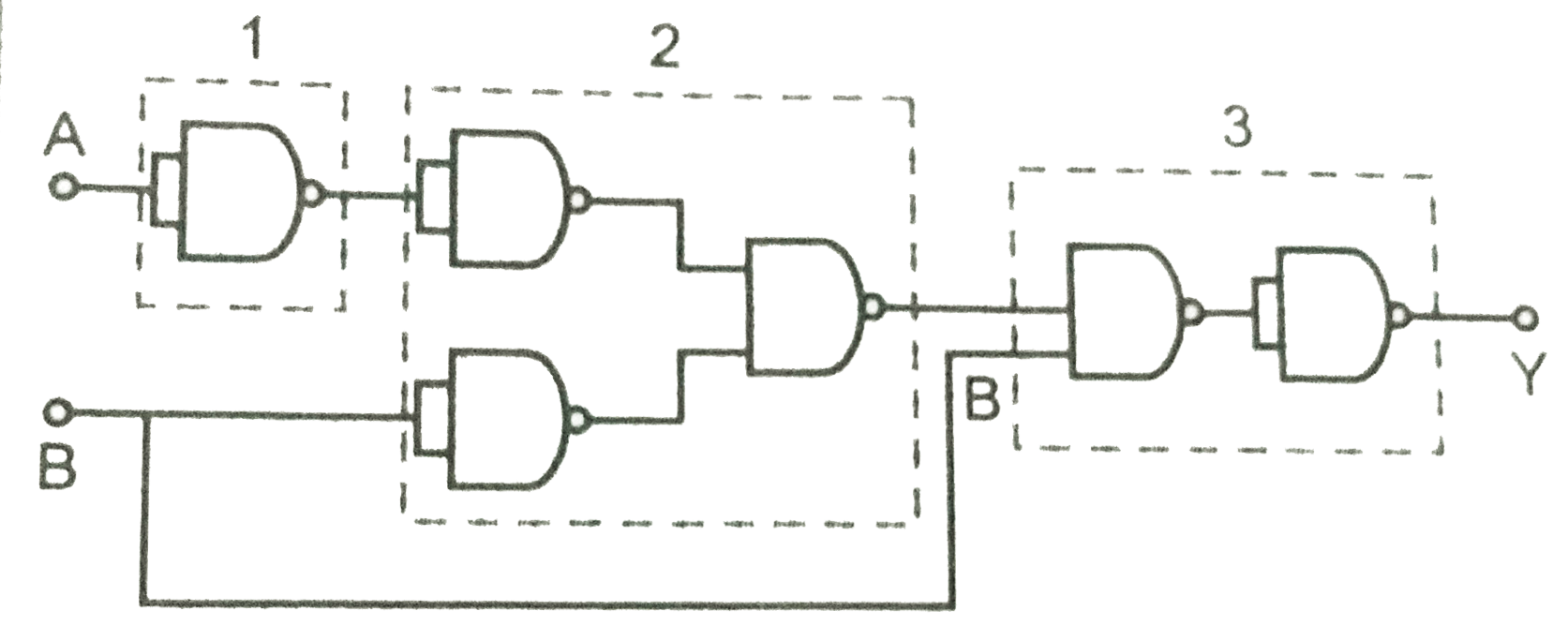
Identify which basic gate, OR, AND and NOT is represented by the circuits in the dotted line boxes 1, 2 and 3 Fig.
Video Solution
Text Solution
In dotted line box 1 is a NOT gate
Explanation. Its circuits is as shown in Fig.

Here y=¯¯¯¯¯¯¯¯A.A=¯¯¯A+¯¯¯A=¯¯¯A=NOTA
In dotted line box 2 is an OR gate.
Explanation. Its circuit is as shown in Fig.
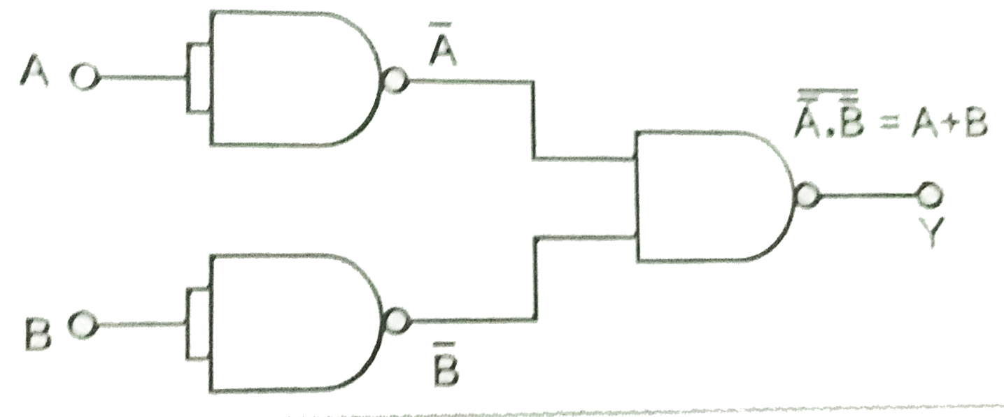
Here, y=¯¯¯¯¯¯¯¯¯¯¯¯A.¯¯¯B=A+B=AORB
(From De-Morgan's Theorem)
In dotted line box 3 is AND gate.
Explanation. Its circuit is as shown in Fig.
 Here, y=¯¯¯¯¯¯¯¯¯¯¯¯¯¯¯¯¯¯¯¯¯¯¯¯(¯¯¯¯¯¯¯¯A.B).¯¯¯¯¯¯¯¯¯¯¯(A.B)=A.B+A.B
Applying de Morgon's theorem
(i) ¯¯¯¯¯¯¯¯¯¯¯¯¯¯¯C+¯¯¯D=C.D(ii)¯¯¯¯¯¯¯¯¯¯¯¯C.¯¯¯D=C+D
∴y=A.B+A.B=A.(B+B)=A.B
=AANDB.(∵B+B=BORB=B)
Similarrly, we can explain the values of y for other values of A and B in truth table.
|
Topper's Solved these Questions
- ELECTRONIC DEVICESBook:PRADEEPChapter:ELECTRONIC DEVICESExercise:SAMPLE PROBLEM
Explore 2 Videos
- ELECTRONIC DEVICESBook:PRADEEPChapter:ELECTRONIC DEVICESExercise:CONCEPTUAL PROBLEMS
Explore 1 Video
- ELECTROMAGNETIC WAVESBook:PRADEEPChapter:ELECTROMAGNETIC WAVESExercise:II Focus multiple choice question
Explore 5 Videos
- ELECTROSTATICSBook:PRADEEPChapter:ELECTROSTATICSExercise:ASSERTION-REASON TYPE QUESTIONS
Explore 2 Videos
Similar Questions
Knowledge Check
Which gate is represented by this figure?
 ANAND gateBAND gateCNOTgateDOR gate
Name the Gate represented by the following circuit.
 AOR gateBXOR gateCAND gateDHAND gate
Which logic gate is represented by the following combination of logic gates
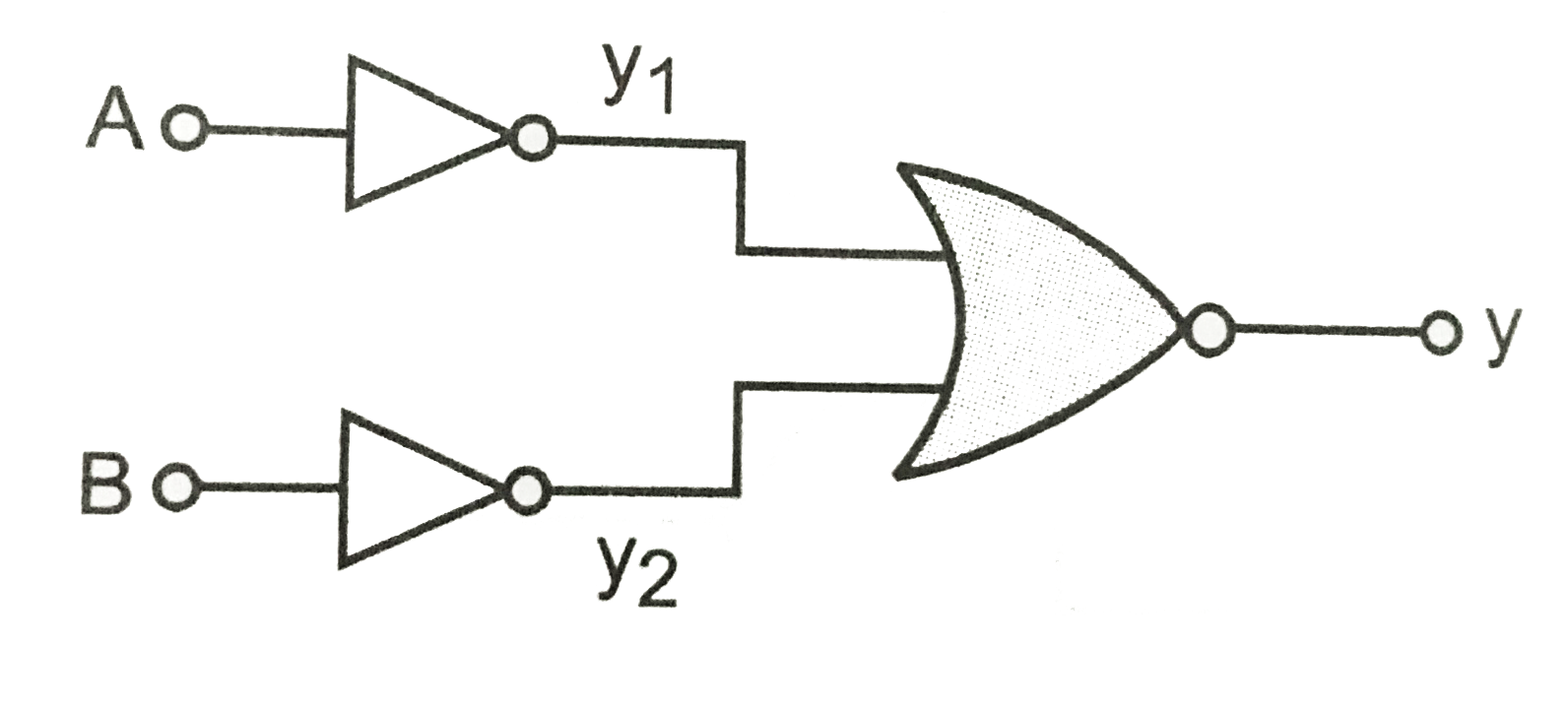 ANANDBANDCNORDOR
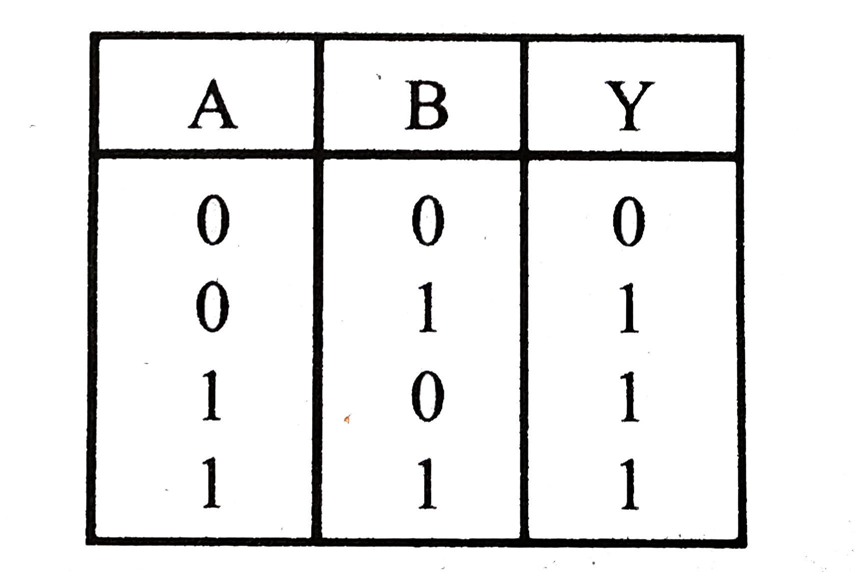
Which logic gate is represented by the following truth table ?
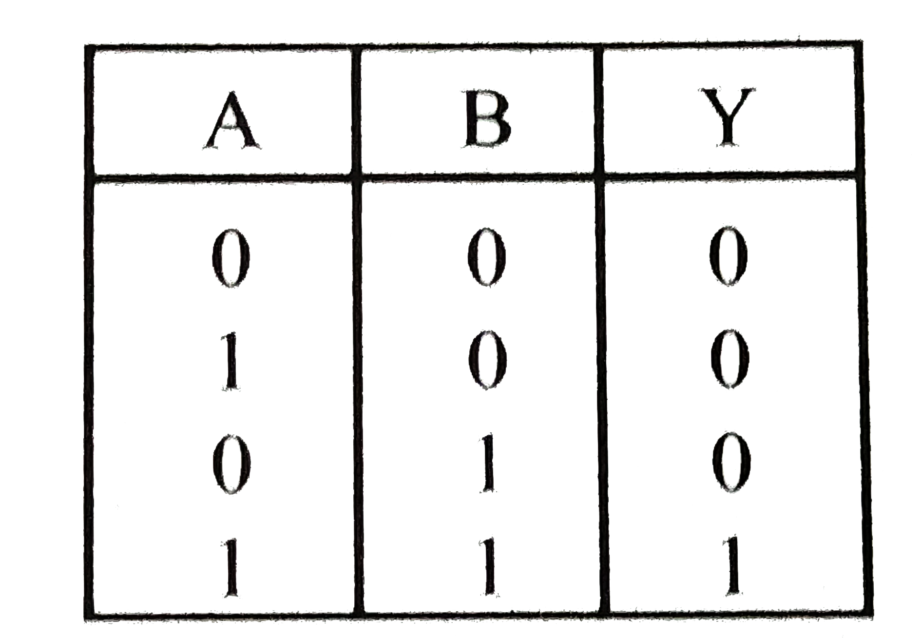
View SolutionIn the circuit shown in fig., the value of I1+I2 is
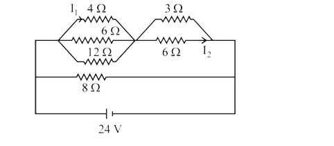
View SolutionWhich logic gate is represented by the following combination of logic gates ?

View SolutionWhich logic gate is represented by the following combination of logic gates

View SolutionWhich logic gate is represented by following diagram?
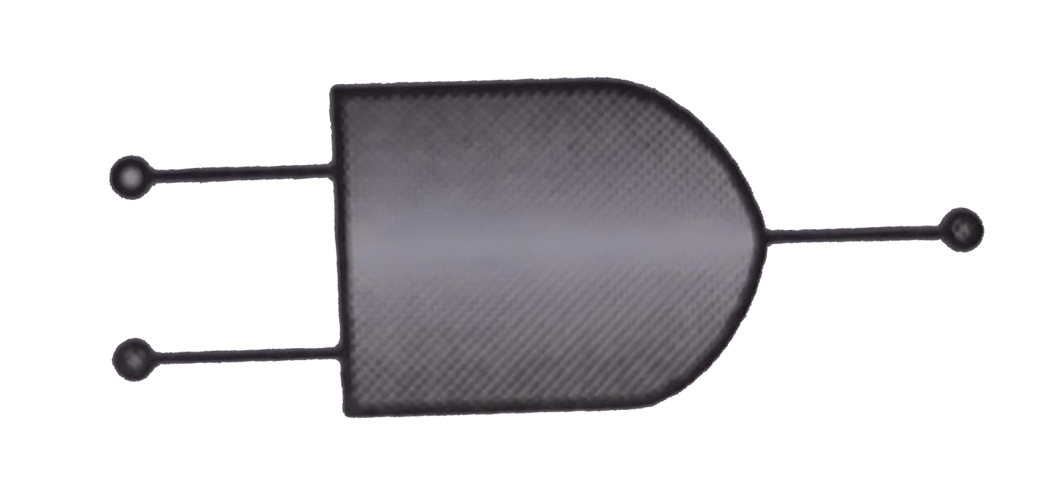
View Solution

