In an LCR circuit as shown below both switches are open initially. Now switch S1 kept open. (q is charge on the capacitor and τ=RC is Capacitive time constant). Which of the following statement is correct?
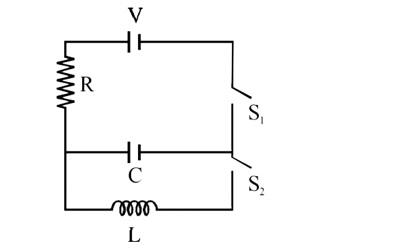
Work done by the battery is half of the energy dissipated in the resistor
At t=τ,q=CV/2
At t=2τ,q=CV(1−e−2)
At t=τ2,q=CV(1−e−1).
The correct Answer is:C
In the figure, when switch S1 is closed and switch S2 is kept open, the condenser gets charged through resistance. At any time t, the charge acquired by the condenser is
Q=Q0(1−e−t/RC), where Q0=CV and RC=τ
At t=2τ,Q=Q0(1−e−2τ/τ)=CV(1−e−2)
Choice (c ) is correct.
Topper's Solved these Questions
- ELECTROMAGNETIC INDUCTION & ALTERNATING CURRENTBook:PRADEEPChapter:ELECTROMAGNETIC INDUCTION & ALTERNATING CURRENTExercise:JEE Mains Ad..(Multiple Choice Question)
Explore 1 Video
- ELECTROMAGNETIC INDUCTION & ALTERNATING CURRENTBook:PRADEEPChapter:ELECTROMAGNETIC INDUCTION & ALTERNATING CURRENTExercise:Multiple Choice Questions
Explore 1 Video
- ELECTROMAGNETIC INDUCTION & ALTERNATING CURRENTBook:PRADEEPChapter:ELECTROMAGNETIC INDUCTION & ALTERNATING CURRENTExercise:Value Based Questions
Explore 2 Videos
- DUAL NATURE OF RADIATION AND MATTERBook:PRADEEPChapter:DUAL NATURE OF RADIATION AND MATTERExercise:Exercise
Explore 191 Videos
- ELECTROMAGNETIC WAVESBook:PRADEEPChapter:ELECTROMAGNETIC WAVESExercise:II Focus multiple choice question
Explore 5 Videos
Similar Questions
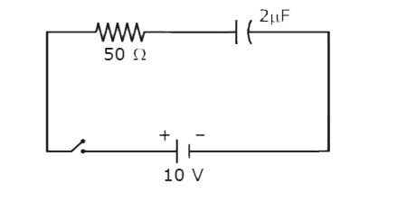
For the circuit shown in figure below, At t = 0, switch is closed, the initial current through resistor and final charge on capacitor are
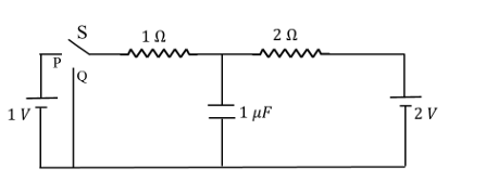
View SolutionIn the circuit shown below, the switch S is connected to position P for a long time so that the charge on the capacitor become q1μC. The S is switched to psition Q. After a long time, the charge on the capacitor is q2μC. The magnitude of q1 is
View Solution
Knowledge Check
A capacitor is charged to a potential of V0. It is connected with an inductor through a switch S. The switch is closed at time t=0. Which of the following statement(s) is/are correct?
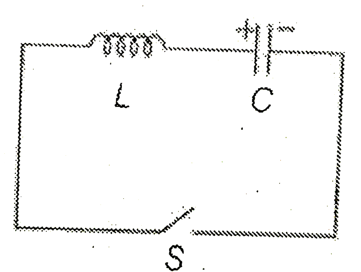 AThe maximum current in the circuit is V0√CLBPotential across capacitor becomes zero for the first time at t=π√LCCEnergy stored in the inductor at time t=π2√LC is 14CV20DMaximum energy stored in the inductor 12CV20
In the circuit shown in the figure, if switches S1 and S2 have been closed for a long time, then charge on the capacitor.
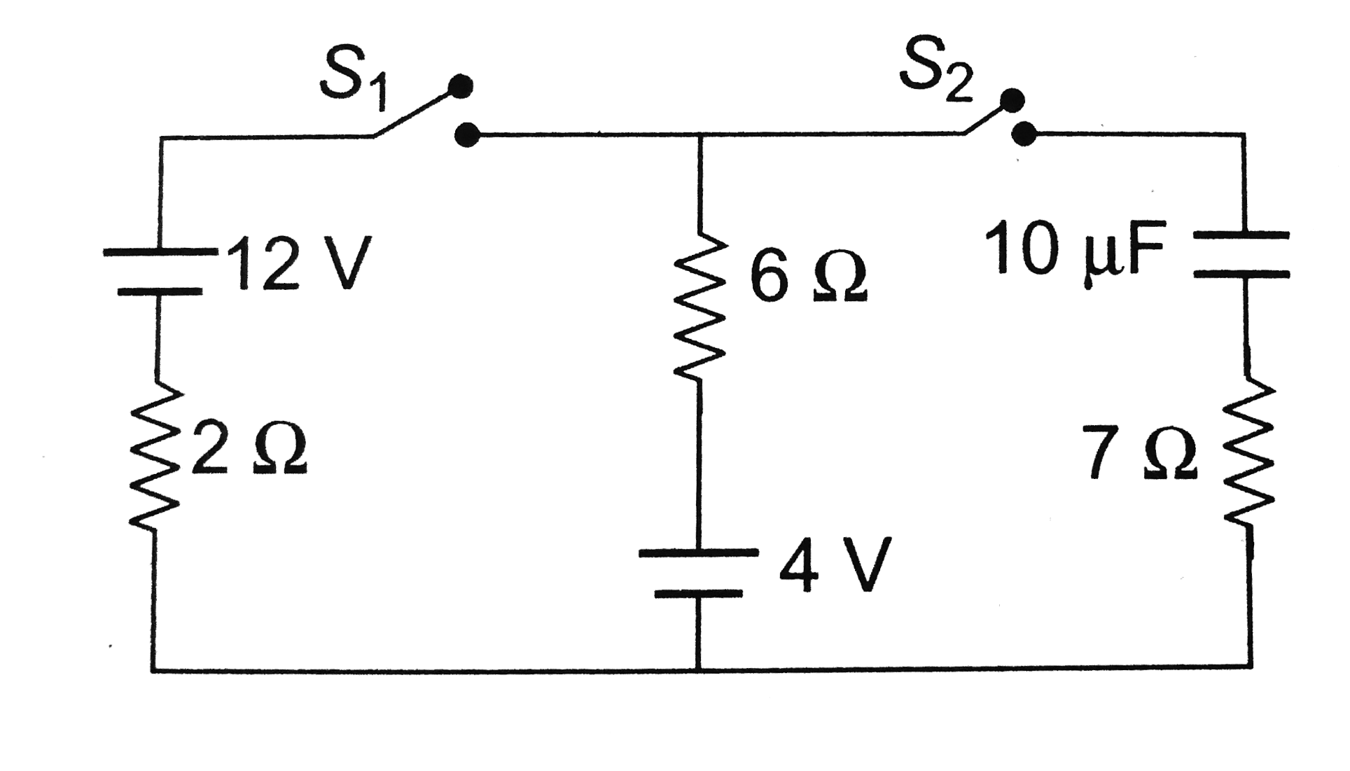 Ais 100μCBincreases to 200μC if one third of the gap of the capacitor's plates is filled with a dielectric (K=2) of same areaCboth (a) and (b) aboveDcharge on the capacitor remains unchanged if one third of the gap of the capacitor's plates is filled with a dielectric (K=2) of same area.
Two plates of a charged capacitor are connected to each through a resistance and a switch which is kept open initially. The switch is closed at t= 0. If q is charge on capacitor and I is the current in the circuit at time t then the curves that correctly represent the variation of the change and current with time are:
A B
B C
C D
D
In the circuit shown below, the switch S is connected to position P for a long time so that the charge on the capacitor become q1μC. The S is switched to psition Q. After a long time, the charge on the capacitor is q2μC. The magnitude of q2 is

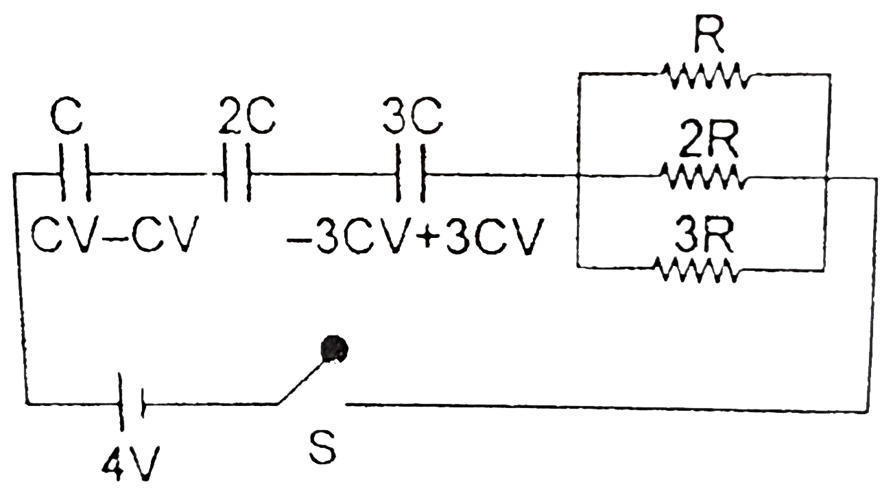
View SolutionThree capacitors (of capacitances C, 2C and 3C) and three resistors (of resistance R, 2R and 3R) are connected with a battery and switch S as shown in the figure. When switch S is open, charges on the capacitors are shown. Switch S is closed at t=0sec. The time constant of the circuit will be
View SolutionIn the given circuit the capacitor (C) may be charged through resistance R by a battery V by closing switch (S1). Also when (S1) is opend and (S2) is closed the capacitor is connected in series with inductor (L).
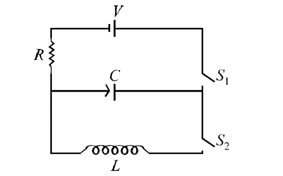
At the start, the capicitor was uncharged. when switch (S1) is closed and (S2) is kept open, the time constant of this circuit is τ. which of the following is correct
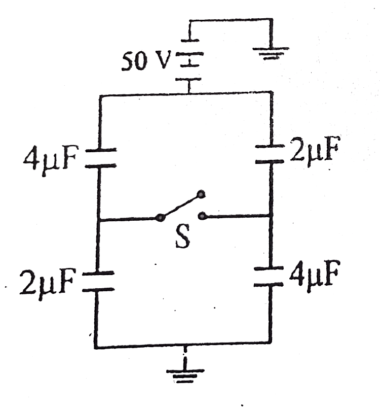
View SolutionThe circuit was in the shown state from a long time. Now the switch S is closed. The charged that flows through the switch is
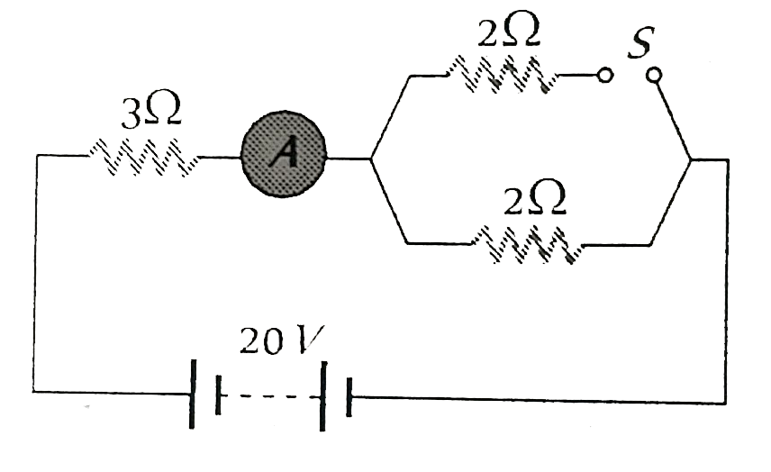
View SolutionIn the circuit shown, the reading of ammeter when switch S is open and when switch S is closed respectively are
View Solution

