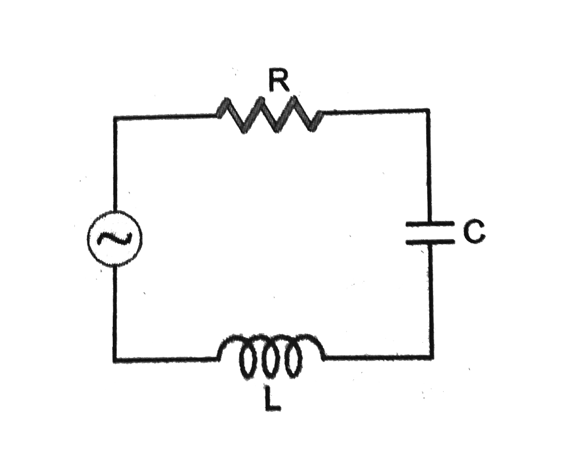
Fig. show a series LCR circuit with L=0.1H,XC=14Ω and R=12Ω connected to a 50 Hz, 200 V source. Calculate
(i) current in the circuit and
(ii) phase angle between current and voltage.
Take π=3

Here, R=12Ω,XC=14ohm
Ev=200V,v=50hz,Iv=?,ϕ=?
XL=ωL=2πvL=2×3×50×0.1
=30ohm.
Z=√R2+(XL−XC)2
=√122+(30−14)2=20ohm
Iv=EvZ=20020=10A
tanϕ=XL−XCR=30−1412=1.33
ϕ=tan−1(1.33)=53.13∘
Topper's Solved these Questions
- ELECTROMAGNETIC INDUCTION & ALTERNATING CURRENTBOOK - PRADEEPCHAPTER - ELECTROMAGNETIC INDUCTION & ALTERNATING CURRENTEXERCISE - Solved Examples (b)
1 Videos
- ELECTROMAGNETIC INDUCTION & ALTERNATING CURRENTBOOK - PRADEEPCHAPTER - ELECTROMAGNETIC INDUCTION & ALTERNATING CURRENTEXERCISE - Short Answer Qusetions
2 Videos
- DUAL NATURE OF RADIATION AND MATTERBOOK - PRADEEPCHAPTER - DUAL NATURE OF RADIATION AND MATTEREXERCISE - Exercise
191 Videos
- ELECTROMAGNETIC WAVESBOOK - PRADEEPCHAPTER - ELECTROMAGNETIC WAVESEXERCISE - II Focus multiple choice question
5 Videos
Similar Questions
Fig. show a series LCR circuit with L=0.1Hl,XC=14Ω and R=12Ω connected to a 50 Hz, 200 V source. Calculate
(i) current in the circuit and
(ii) phase angle between current and voltage.
Take π=3

View SolutionA 0.21H inductor and a 12ohm resistance are connected in series to a 220V. 50Hz ac source. Calculate the current in the circuit and the phase angle between the current and the source voltage.
View Solution
Knowledge Check
A 0.21 H inductor and a 12Ω resistance are connected in series to a 220 V, 50 Hz ac source.
The current in the circuit isA220√4400AB223√5AC220√4500AD225√3AA 0.21-H inductor and a 88−Ω resistor are connected in series to a 220-V, 50-Hz AC source. The current in the circuit and the phase angle between the current and the source voltage are respectively. (Useπ=22/7)
A2A,tan−13/4B14.4A,tan−17/8C14.4A,tan−18/7D3.28A,tan−12/11In series LCR circuit, the phase angle between supply voltage and current is
Atanϕ=XL−XCRBtanϕ=RXL−XCCtanϕ=RXL+XCDtanϕ=XL+XCR
A 9/100(π) inductor and a 12Ω resistanace are connected in series to a 225 V, 50 Hz ac source. Calculate the current in the circuit and the phase angle between the current and the source voltage.
View SolutionA 31.4Ω resistor and 0.1H inductor are connected in series to a 200V, 50Hz ac source. Calculate
(i) the current in the circuit
View SolutionA 9100π H inductor and a 12ohm resitance are connected in series to a 225V, 50Hz ac source. Calculate the current in the circuit and the phase angle betweent the current and the source voltage.
View SolutionA series LCR circuit with L=4.0h,C=100μF and R=60Ω is connected to a varialbe frequency 240 V source. Calcalate
(i) angular frequency of the source which drives the circuit in resonace,
(ii) current at the resonating frequency,
(iii) rms potential drop across the inductro at resonance.
View SolutionA 200Ω resistor is connected to a 220 V, 50 Hz AC supply. Calculate rms value of current in the circuit. Also find phase difference between voltage and the current.
View Solution
