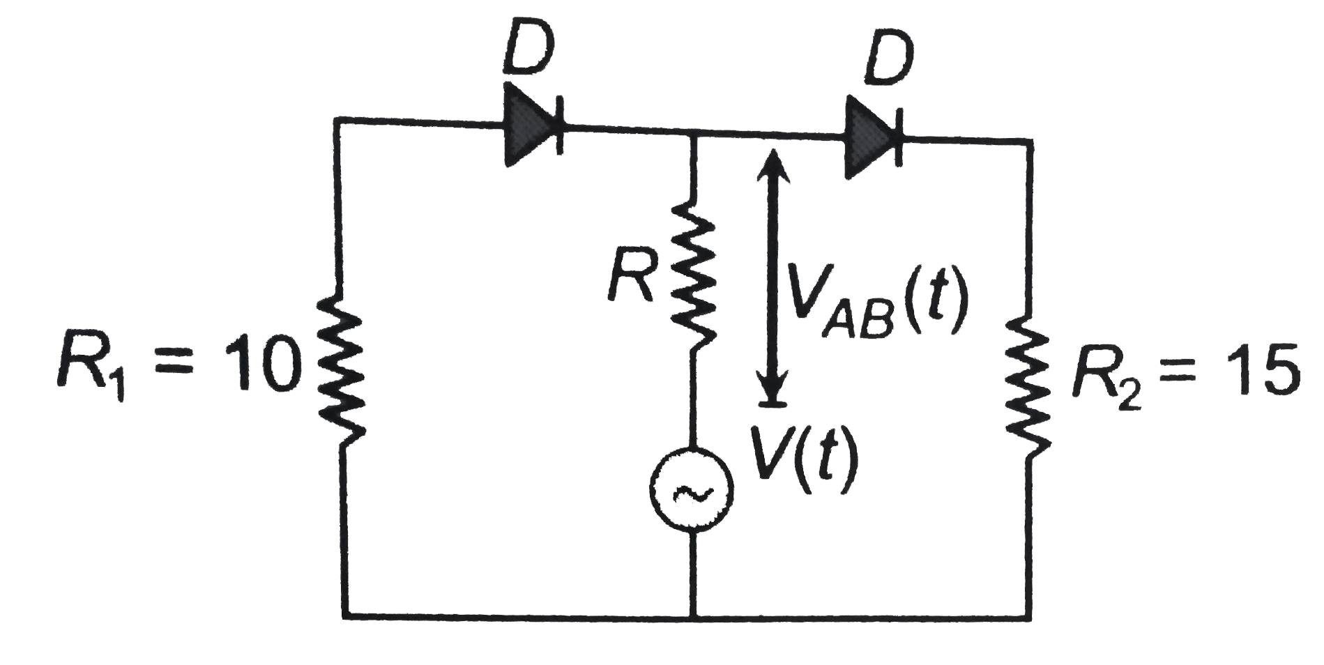
In the circuit given below, V(t) is the sinusoidal voltage source, voltage drop VAB(t) across the resistance R is

Is half wave rectified
Is full wave rectified
Has the same peak value in the positive and negative half cycles
Has different peak values during positive and negative half cycle
The correct Answer is:D
In positive half cycle one diode is in forward biasing and other is in reverse biasing while in negative half cycle their polarity reverses, and direction of current is opposite through R for positive and negative half cycles so output is not rectified.
Topper's Solved these Questions
- SEMICONDUCTOR ELECTRONICSBOOK - A2ZCHAPTER - SEMICONDUCTOR ELECTRONICSEXERCISE - SECTION -D
1 Videos
- NUCLEAR PHYSICSBOOK - A2ZCHAPTER - NUCLEAR PHYSICSEXERCISE - Section D - Chapter End Test
29 Videos
- SOURCE AND EFFECT OF MAGNETIC FIELDBOOK - A2ZCHAPTER - SOURCE AND EFFECT OF MAGNETIC FIELDEXERCISE - Section D - Chapter End Test
30 Videos
Similar Questions
Knowledge Check
In the circuit given below, V(t) is the sinusoidal voltage source, voltage drop VAB(t) across the resistance R is
 AIs half wave rectifiedBIs full wave rectifiedCHas the same peak value in the positive and negative half cyclesDHas different peak values during positive and negative half cycle
A 20volts AC is applied to a circuit consisting of a resistance and a coil with negligible resistance. If the voltage across the resistance is 12V, the voltage across the coil is
A16 voltsB10 voltsC8 voltsD6 voltsA 120V,60Hz a.c. power is connected 800Ω non-inductive resistance and unknown capacitance in series. The voltage drop across the resistance is found to be 102V, then voltage drop across capacitor is
A8VB102VC63VD55V
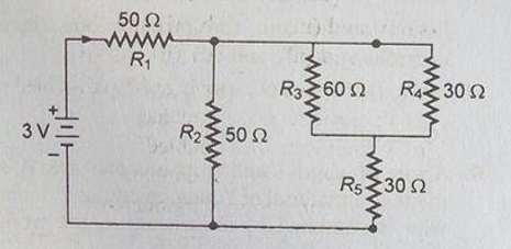
In circuit show below, the resistances are given in ohms and the battery is assumed ideal with emf equal to 3 V. The voltage across the resistance R4 is :

View SolutionIn circuit show below, the resistances are given in ohms and the battery is assumed ideal with emf equal to 3 V. The voltage across the resistance R4 is :

View SolutionIn a series L−C−R circuit, currenrt in the circuit is 11A when the applied voltage is 220V. voltage across the caspcitor is 200V. If the value of resistor is 20Ω, then the voltage across the unknown inductor is
View SolutionIf the input voltage Vi to the circuit below is given by Vi(t)=Acos(2πft), the output voltage is given by Vo(t)=Bcos(2πft+ϕ)-

Which one of the following four graphs best depict the variation of ϕ vs f ?
View SolutionCalculate the potential across the capacitance if 50 V AC is applied across RC circuit and the rms voltage across the resistance is 40 V.
View Solution


