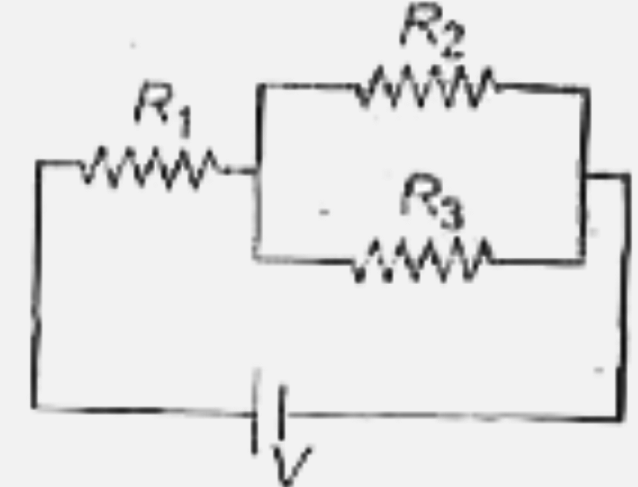
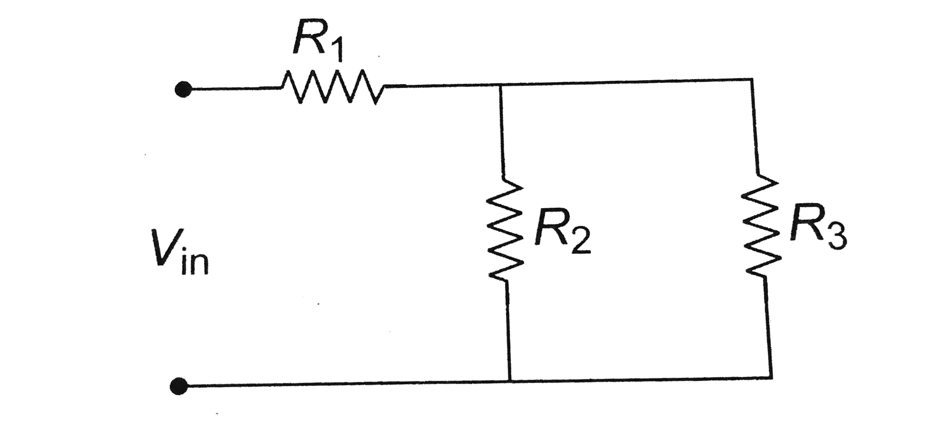
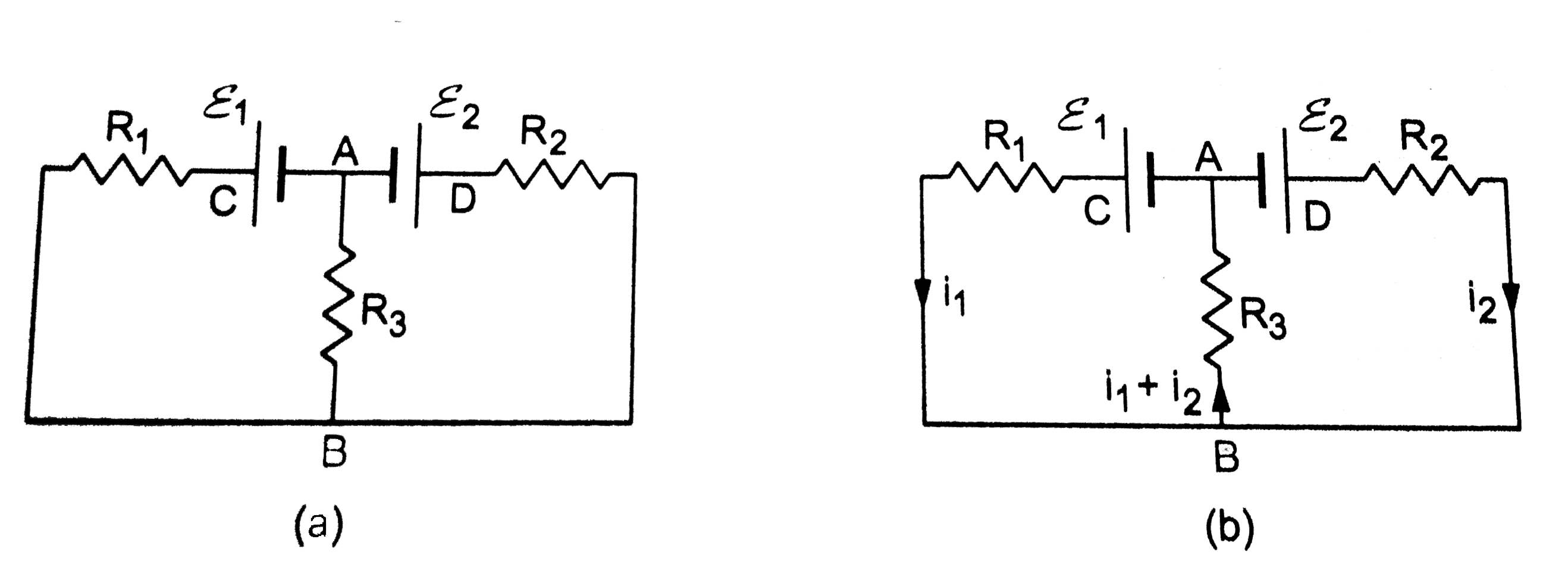
For ensuring dissipation of same energy in all three resistors (R1,R2,R3) connected as shown in figure, their values must be related s
R1=R2=R3
R2=R3 and R1=4R2
R2=R3 and R1=14R2
R1=R2+R3
The correct Answer is:C
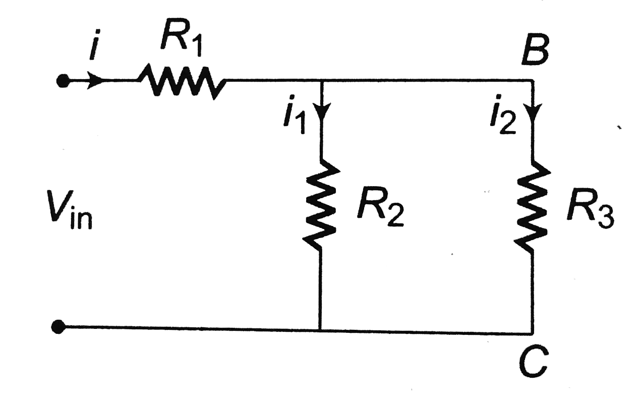
(c ) In the given circuit the resistor's R2 and R3 are connected in parallel hence potential difference (V) across them is same. In order that they undergo same energy loss,
Here H=V2Rt
Hence R2 must be equal to R3.
i.e., R2=R3
H=V2R.t,R2=R3 ∴i2R1t=i21R2t
Using i1=R3R2+R3i=R3R3+R3i=12i
Thus i2=R1t=i24R2t or , R1=R24
Topper's Solved these Questions
- CURRENT ELECTRICITYBOOK - A2ZCHAPTER - CURRENT ELECTRICITYEXERCISE - Assertion- Reason
14 Videos
- CURRENT ELECTRICITYBOOK - A2ZCHAPTER - CURRENT ELECTRICITYEXERCISE - Section D - Chapter End Test
29 Videos
- CURRENT ELECTRICITYBOOK - A2ZCHAPTER - CURRENT ELECTRICITYEXERCISE - Section - C
1 Videos
- ATOMIC PHYSICSBOOK - A2ZCHAPTER - ATOMIC PHYSICSEXERCISE - Section D - Chapter End Test
30 Videos
- DUAL NATURE OF RADIATION AND MATTERBOOK - A2ZCHAPTER - DUAL NATURE OF RADIATION AND MATTEREXERCISE - Section D - Chapter End Test
30 Videos
Similar Questions
Knowledge Check
For ensuring disspation of same energy in all three resistors (R1,R2,R3) connected as shown in figure, their values must be related as –
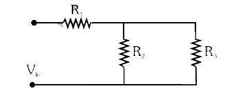 AR1=R2=R3BR2=R3andR1=4R2CR2=R3andR1=14R2DR1=R2+R3
Two ideal batteries of emf V1andV2 and three resistances R1,R2andR3 are connected as shown in the figure. The current in resistance R2 would be zero if
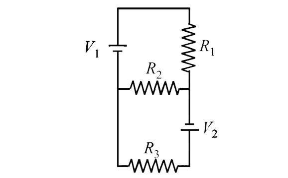 AV1=V2andR1=R2=R3BV1=V2andR1=2R2=R3CV1=2V2and2R1=2R2=R3D2V1=V2and3R1=R2=R3
Three equal resistors, each equals to r are connected as shown in figure. Then, the equivalent resistance between points A and B is
ArB3rCr3D2r3
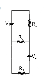
Two ideal batteries of emf V1andV2 and these resistances R1,R2andR3 are connected as shown in the figure . The current in resistance R2 would be zero if
View SolutionIf resistors of resistance R1 and R2 are connected in parallel,then resultant resistance is "
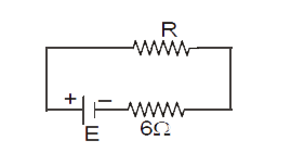
View SolutionA resistor R is connected to a cell as shown in the figure. The value of R for which in its is maximum is:-
View SolutionFind the currents going through the three resistors R_(v),R_(2)andR_(3) in the circuit of figure.
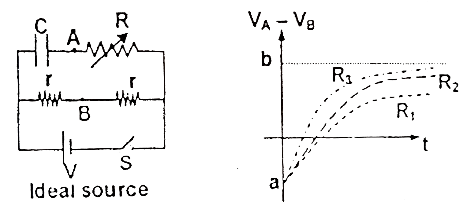
View SolutionAn uncharged capacitor C and a variable resistance R are connected to an ideal source and two resistors with the help of a switch at t=0 as shown in the figure. Initially capacitor is uncharged and switch S is closed at t=0sec. The graph between VA−VB for variable Resistor R for its three different values R1, R2, and R3 versus time is shown in the figure II. Choose the correct statement
View Solution

