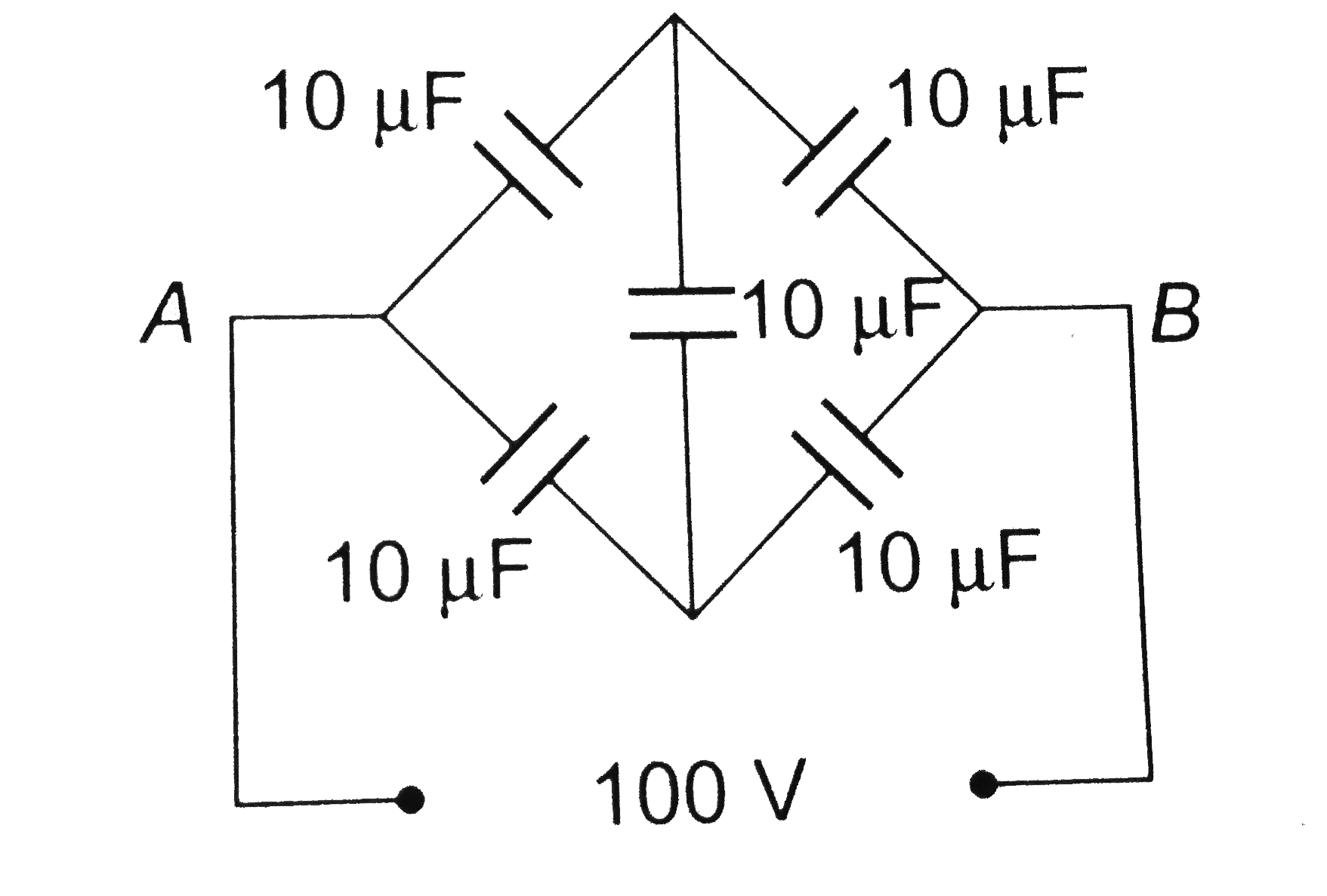
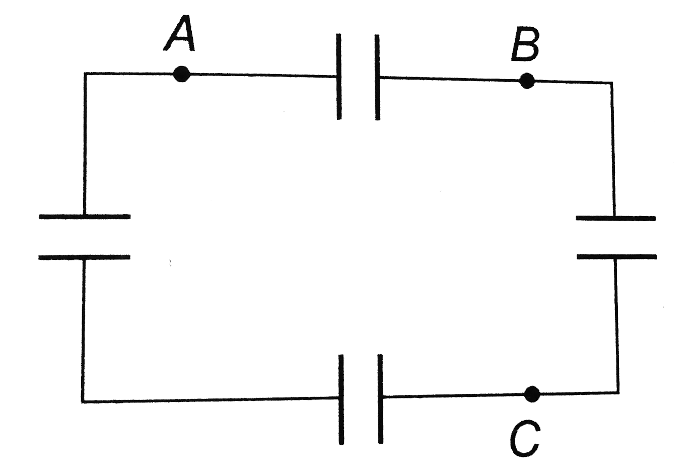
Five capacitors of 10μf capacity each are connected to a.d.c potential of 100 volts as shown in the adjoining figure. The equivalent capacitance between the points A and B will be equal to
A
40μF
B
20μF
C
30μF
D
10μF
Video Solution
Text Solution
The correct Answer is:D
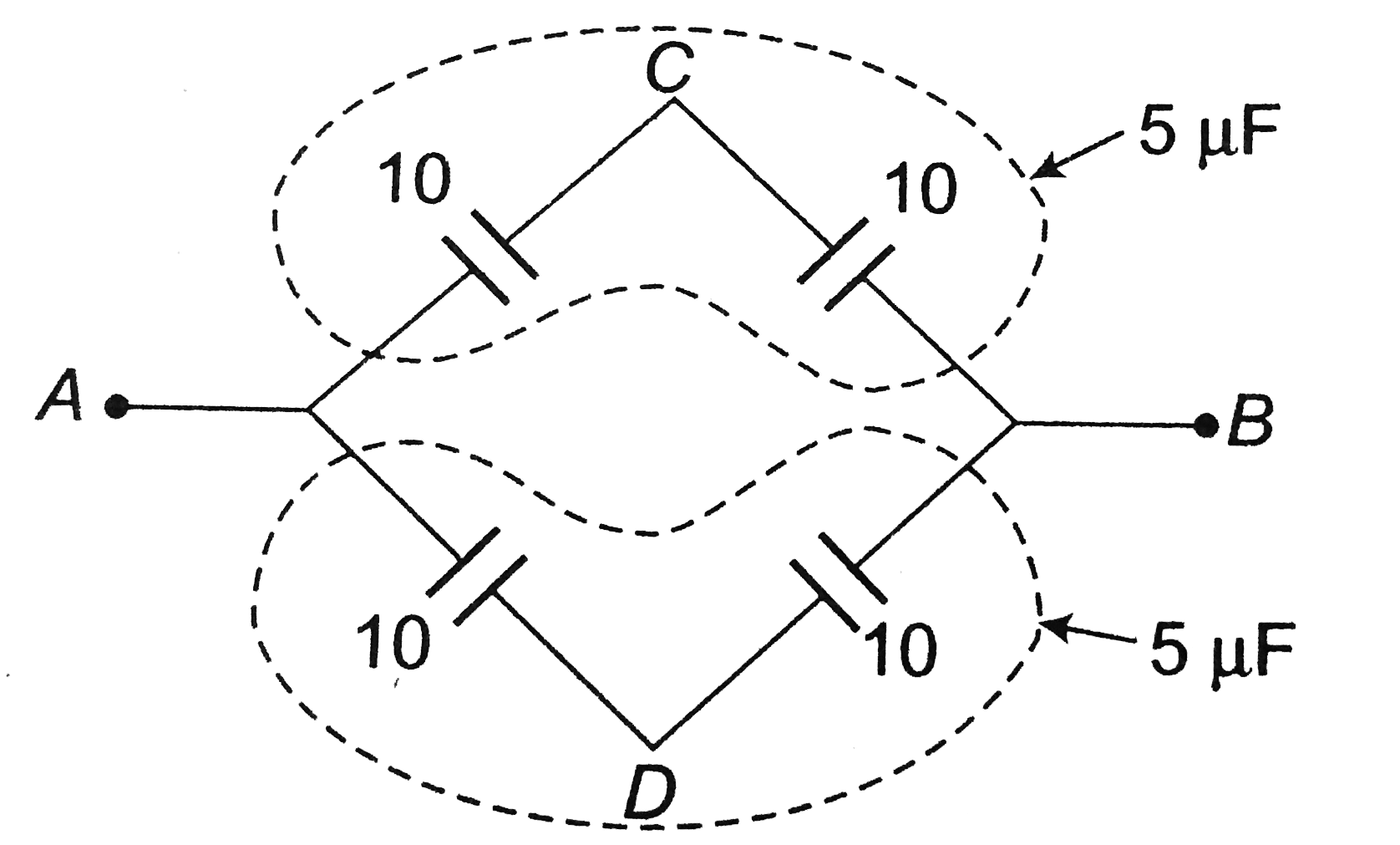
In the given system, no currect will flow through branch CD so if can be removed
Effective capacitance of the system =5+5=10μF
|
Topper's Solved these Questions
- ELECTRIC POTENTIAL & CAPACITANCEBook:A2ZChapter:ELECTRIC POTENTIAL & CAPACITANCEExercise:Assertion Reason
Explore 8 Videos
- ELECTRIC CHARGE, FIELD & FLUXBook:A2ZChapter:ELECTRIC CHARGE, FIELD & FLUXExercise:Section D - Chapter End Test
Explore 29 Videos
- ELECTROMAGNETIC INDUCTIONBook:A2ZChapter:ELECTROMAGNETIC INDUCTIONExercise:Section D - Chapter End Test
Explore 30 Videos
Similar Questions
Knowledge Check
In the connection shown in the adjoining figure, the equivalent capacity between A and B will be
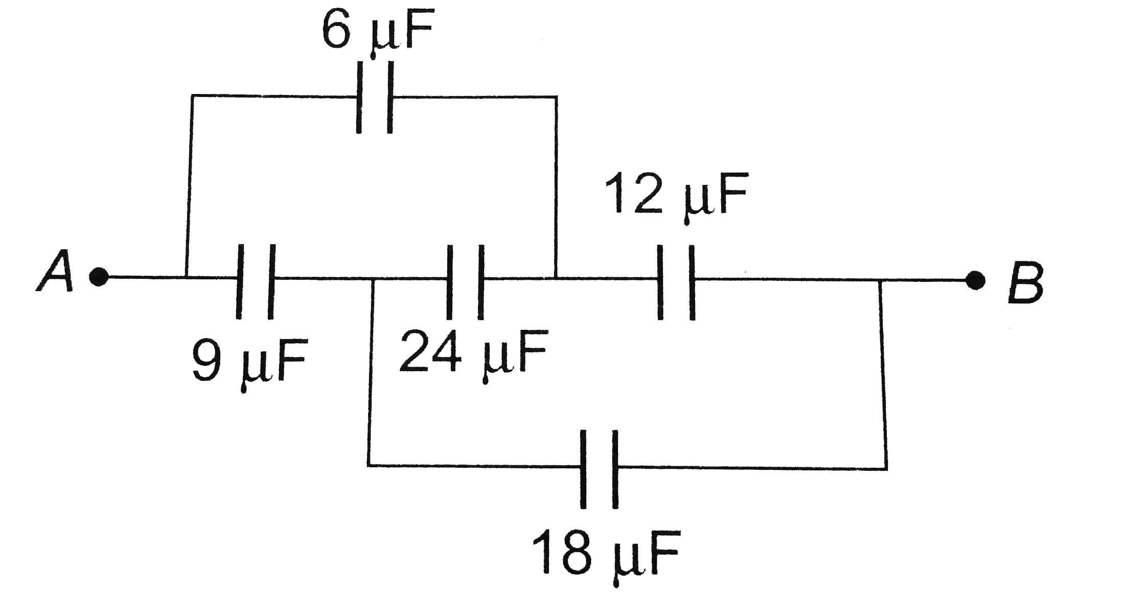 A10.8μFB69μFC15μFD10μF
Four capacitors are connected as shown in Fig. The equivalent capacitance between the points A and B is
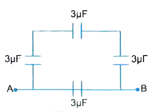 A12μFB2.25μFC4μFD0.75μF
Each capacitor shown in the figure is 2μF. Then the equivalent capacitance between points A and B is
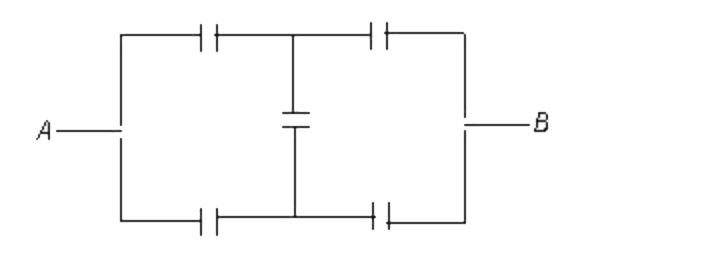 A2μFB4μFC6μFD8μF
Five resistance are connected as shown in the figure. The equivalent resistance between points A and C is
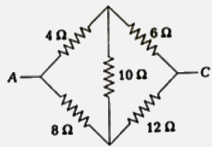
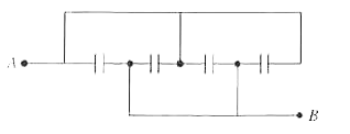
View SolutionFour capacitors each of 8μF, are joined as shown in the figure. The equivalent capacitance between the points A and B is
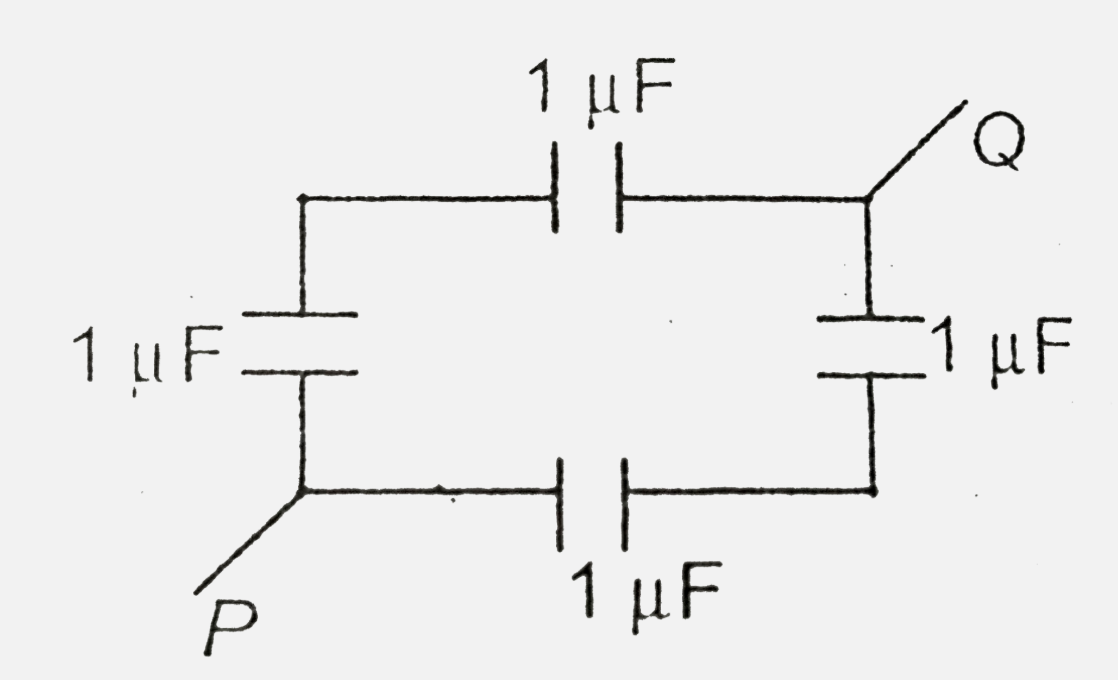
View SolutionFour capacitors are connected as shown . The equivalent capacitance between the points P and Q is

View SolutionFour capacitors, each of 1μF, are joined as shown in Fig.The equivalent capacitance between the points A and B is

View SolutionFour capacitors of each of capacity 3μF are connected as shown in the adjoining figure. The ratio of equivalent capacitance between A and B and between A and C will be
View Solution

