_________ is an important anti knock compound added to petrol used in internal combustion engines .
The correct Answer is:Tetrahedral lead (TEL)
Step by step video, text & image solution for _________ is an important anti knock compound added to petrol used in internal combustion engines . by Chemistry experts to help you in doubts & scoring excellent marks in Class 12 exams.
Updated on:21/07/2023Topper's Solved these Questions
- COORDINATION COMPOUNDSBOOK - CENGAGE CHEMISTRYCHAPTER - COORDINATION COMPOUNDSEXERCISE - Exercises True/False
14 Videos
- COORDINATION COMPOUNDSBOOK - CENGAGE CHEMISTRYCHAPTER - COORDINATION COMPOUNDSEXERCISE - Archives (Linked Comprehension)
5 Videos
- COORDINATION COMPOUNDSBOOK - CENGAGE CHEMISTRYCHAPTER - COORDINATION COMPOUNDSEXERCISE - Exercises Integer (Hybridisation , Vbt , Cft And Application)
13 Videos
- CHEMICAL KINETICSBOOK - CENGAGE CHEMISTRYCHAPTER - CHEMICAL KINETICSEXERCISE - Archives Subjective
23 Videos
- D AND F BLOCK ELEMENTSBOOK - CENGAGE CHEMISTRYCHAPTER - D AND F BLOCK ELEMENTSEXERCISE - Archives Subjective
29 Videos
Similar Questions
Knowledge Check
A knocking sound is produced in the internal combustion engine when the fuel
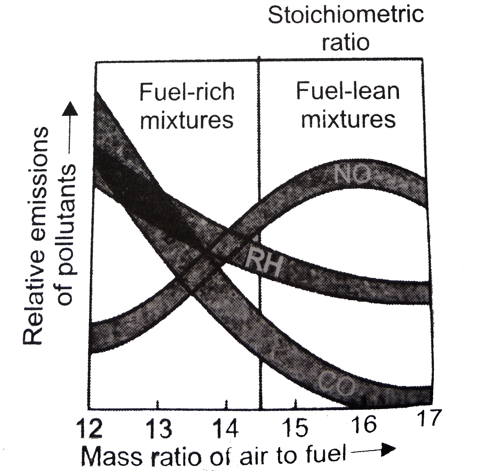
Aburns slowlyBburns fastCcontains some waterDis contaminated with lubricating oil.The figure showns how the emission of pollutants is related to the air/fuel ratio in an internal comustion engine using octance C8H18 . Select the correct statement(s).
 AExcess air leads to high NO(g) levelsBUnburnt and partially burnt hydrocarbons lead to high RH and CO levelCStoichiometric ratio of air to fuel (on a mass basis) is about 14.5:1 if air contains 24%O2DAll of the above
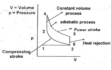
To move an airplane through the air, thrust is generated by some kind of propulsion system. Beginning with the Wright brothers' first flight, many airplanes have used internal combustion engines to turn propellers to generate thrust. Today, most general aviation or private airplanes are powered by internal combustion (IC) engines, much like the engine in your family automobile. When discussing engines, we must consider both the mechanical- operation of the machine and the thermodynamic processes that enable the machine to produce useful work. We consider the thermodynamics of a four-stroke IC engine.

Figure shown represents such a cycle which is used in all Internal combustion engines. The figure shows a p-V diagram of the cycle. Using the engine stage numbering system, we begin at the lower left with Stage 1 being the beginning of the intake stroke of the engine. The pressure is near atmospheric pressure and the gas volume is at a minimum. Between Stage 1 and Stage 2 the piston is pulled out of the cylinder with the intake valve open. The pressure remains constant, and the gas volume increases as fuel/air mixture is drawn into the cylinder through the-intake valve. Stage 2 begins the compression stroke of the engine with the closing of the intake valve. Between Stage 2 and Stage 3, the piston moves back into the cylinder, the gas volume.decreases, and the pressure increases because work is done on the gas by the piston. Stage 3 is the beginning of the combustion of the fuel/air mixture. The combustion occurs very quickly and the volume remains constant. Heat is released during combustion which increases both the temperature and the pressure, according to the equation of slate. Slage 4 begins the power stroke of the engine. Between Stage 4 and Stage 5, the piston is driiven towards the crankshaft, the volume in increased, and the pressure falls as work is done by the gas on the píston. At Stage 5 the exhaust valve is opened and the residual heat in the gas is exchanged with the surroundings. The volume remains constant and the pressure adjusts back to atmospheric conditions. Stage 6 begins the exhaust stroke of the engine during which the piston. moves back into the cylinder, the volume decreases and the pressure remains constant. At the end of the exhaust stroke, conditions have returned to Stage 1 and the process repeats itself. During the cycle, work is done on the gas by the plston between stages 2 and 3. Work is done by the gas on the piston between stages 4 and 5. The difference between the work done by the gas and the work done on the gas is the area enclosed by the cycle curve and is the work produced by the cycle. The work times the rate of the cycle (cycles per second) is equal to the power produced by the engine.
Consider that the above diagram represents an ideal such cycle then choose the incorrect statement fora corresponding real cycle.AThe area of the p-V diagram for the real cycle will be lesser than that for ideal cycle.BThe shape of the p-V diagram for the real cycle will be similar to the corresponding ideal cycle.CThe power produced by the engine for an ideal cycle will be greater than that produced by corresponding real cycle.DThe shape of the p-V diagram for the real cycle will not be similar to the ideal cycle.
Distinguish between internal and external combustion heat engines.
View SolutionWhich compound is generally added to petrol to make it burn smoothly in automobile engines ?
View SolutionWrite Lewis structure for the following
(a) Ethene (C2H4) the most important reactant in polymer manufacture
(b) Nitrogen (N2) the most abundant atmosheric gas
(c ) Methanol (CH4O) an important industrial alcohol that is beign used as a gasoline alternative in car engines .
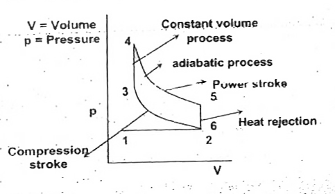
View SolutionTo move an airplane through the air, thrust is generated by some kind of propulsion system. Beginning with the Wright brothers' first flight, many airplanes have used internal combustion engines to turn propellers to generate thrust. Today, most general aviation or private airplanes are powered by internal combustion (IC) engines, much like the engine in your family automobile. When discussing engines, we must consider both the mechanical- operation of the machine and the thermodynamic processes that enable the machine to produce useful work. We consider the thermodynamics of a four-stroke IC engine.

Figure shown represents such a cycle which is used in all Internal combustion engines. The figure shows a p-V diagram of the cycle. Using the engine stage numbering system, we begin at the lower left with Stage 1 being the beginning of the intake stroke of the engine. The pressure is near atmospheric pressure and the gas volume is at a minimum. Between Stage 1 and Stage 2 the piston is pulled out of the cylinder with the intake valve open. The pressure remains constant, and the gas volume increases as fuel/air mixture is drawn into the cylinder through the-intake valve. Stage 2 begins the compression stroke of the engine with the closing of the intake valve. Between Stage 2 and Stage 3, the piston moves back into the cylinder, the gas volume.decreases, and the pressure increases because work is done on the gas by the piston. Stage 3 is the beginning of the combustion of the fuel/air mixture. The combustion occurs very quickly and the volume remains constant. Heat is released during combustion which increases both the temperature and the pressure, according to the equation of slate. Slage 4 begins the power stroke of the engine. Between Stage 4 and Stage 5, the piston is driiven towards the crankshaft, the volume in increased, and the pressure falls as work is done by the gas on the píston. At Stage 5 the exhaust valve is opened and the residual heat in the gas is exchanged with the surroundings. The volume remains constant and the pressure adjusts back to atmospheric conditions. Stage 6 begins the exhaust stroke of the engine during which the piston. moves back into the cylinder, the volume decreases and the pressure remains constant. At the end of the exhaust stroke, conditions have returned to Stage 1 and the process repeats itself. During the cycle, work is done on the gas by the plston between stages 2 and 3. Work is done by the gas on the piston between stages 4 and 5. The difference between the work done by the gas and the work done on the gas is the area enclosed by the cycle curve and is the work produced by the cycle. The work times the rate of the cycle (cycles per second) is equal to the power produced by the engine.
Choose.the correct statement.
View SolutionIncomplete combustion of petrol or diesel in automobile engine produces
View Solution
