In the arrangement shown in figure when the switch S2 is open, the galvanometer shown no deflection for l=L/2. When the switch S2 is closed, the galvanometer shown no deflection for l=5L/12. The internal resistance (r) of 6V cell, and the emf E of the other battery are respectively

3Ω,8V
2Ω,12V
2Ω,24V
3Ω,12V
The correct Answer is:B
b. When switch S1 is open
6E=L2/L=12
∴E=12V
When switch S2 is closed, we get
6×10¹⁰+r=5L12LE=512×12=5
∴10+r=12orr=2Ω
Similar Questions
Knowledge Check
In the circuit shown in figure, switch S is initially closed and S is open. Find V-V
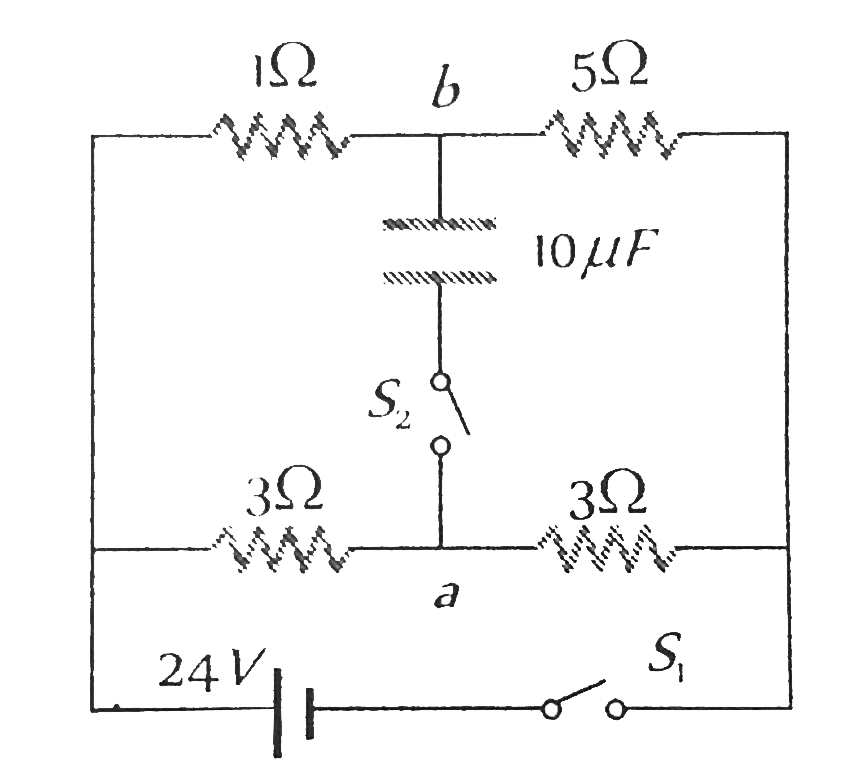 A4VB8VC12VD16V
Consider the situation shown in figure (31-E23 ) . The switch S is open for a long time and then closed . (a) Find the charge flown through the battery when the switch S is closed (b)Find the done by the battery .
 AC∈/2BC∈/4CC∈Dnone of these
In the circuit shown, the reading of ammeter when switch S is open and when switch S is closed respectively are
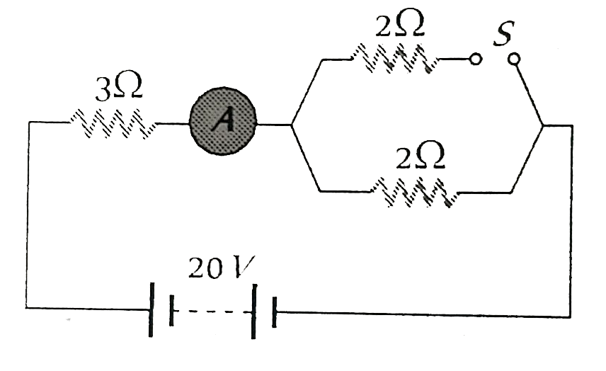 A3A and 4AB4A and 5AC5A and 6AD6A and 7A
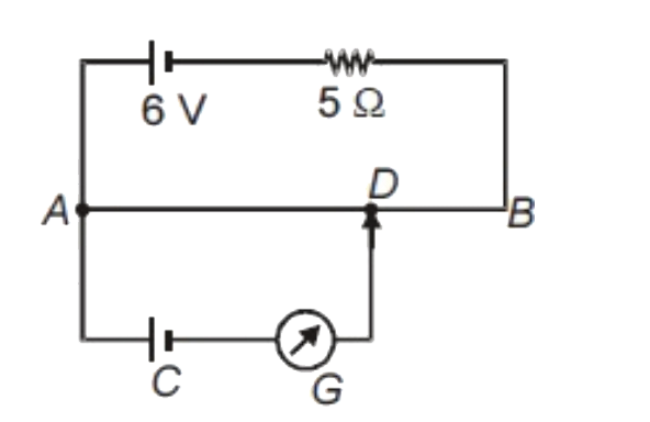
In the potentiometer circuit shown in the figure the internal resistance of the 6V battery is 1Ω and length of the wire AB is 100 cm . When AD = 60 cm , the galvanometer shows no deflection . The EMF of the cell C is (the resistance of the wire AB is 2Ω )
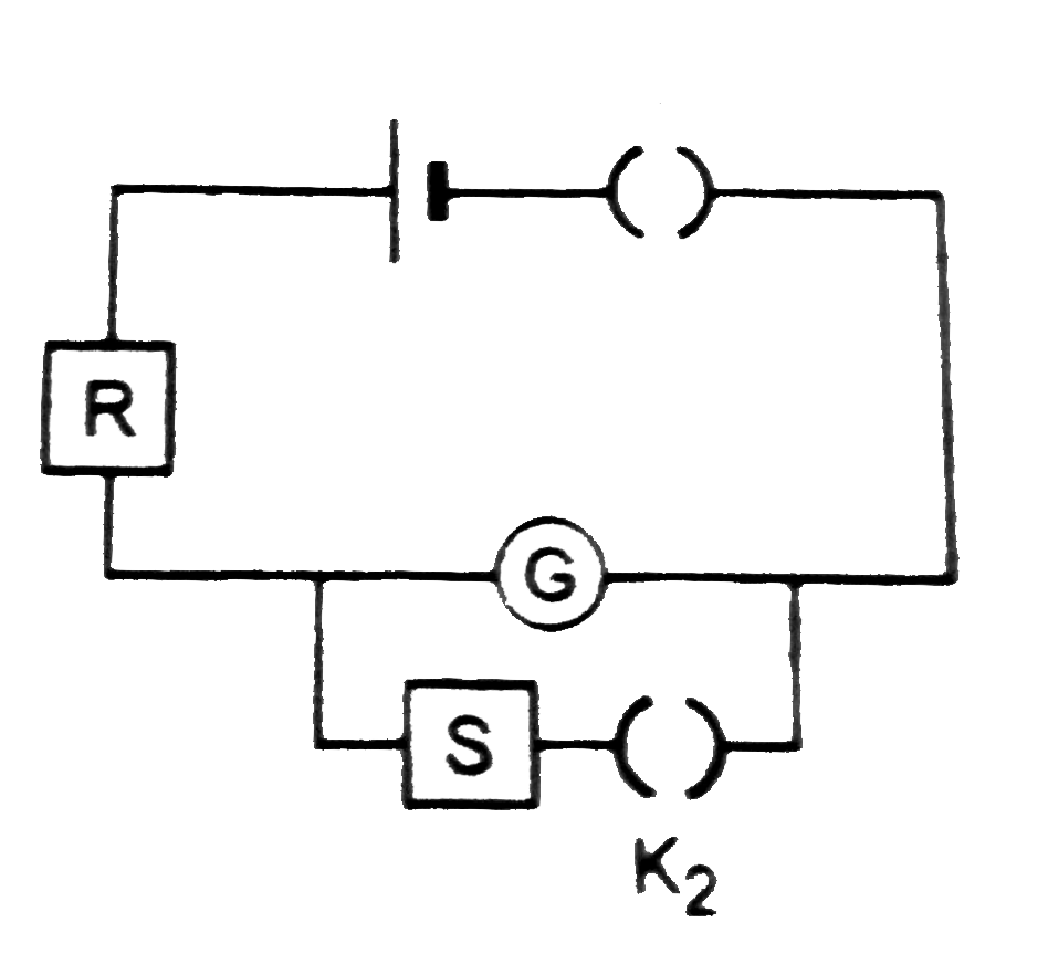
View SolutionIn the circuit, shown in figure. R=5000Ω. If key K1 is closed, galvanometer shows a deflection of 30 scale division. On closing key K2 and making S=20Ω, the deflection of galvanometer reduces to 15 division. The resistance of galvanometer is
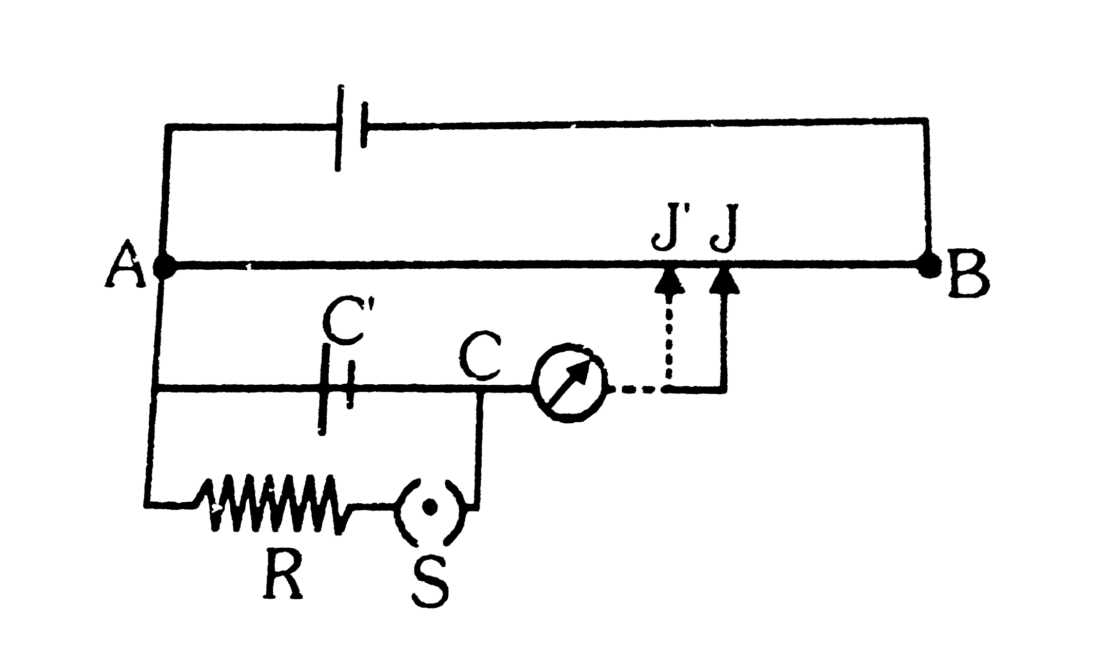
View SolutionIn the potentiometer circuit shown in the figure the balance length AJ=60cm when switch S is open. When switch S is closed and the value of R=5Ω, the b alance length AJ=50cm. The internal resistance of the cell C' is
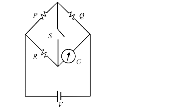
View SolutionIn the circuit P≠R, the reading of the galvanometer is same with switch S open or closed. Then
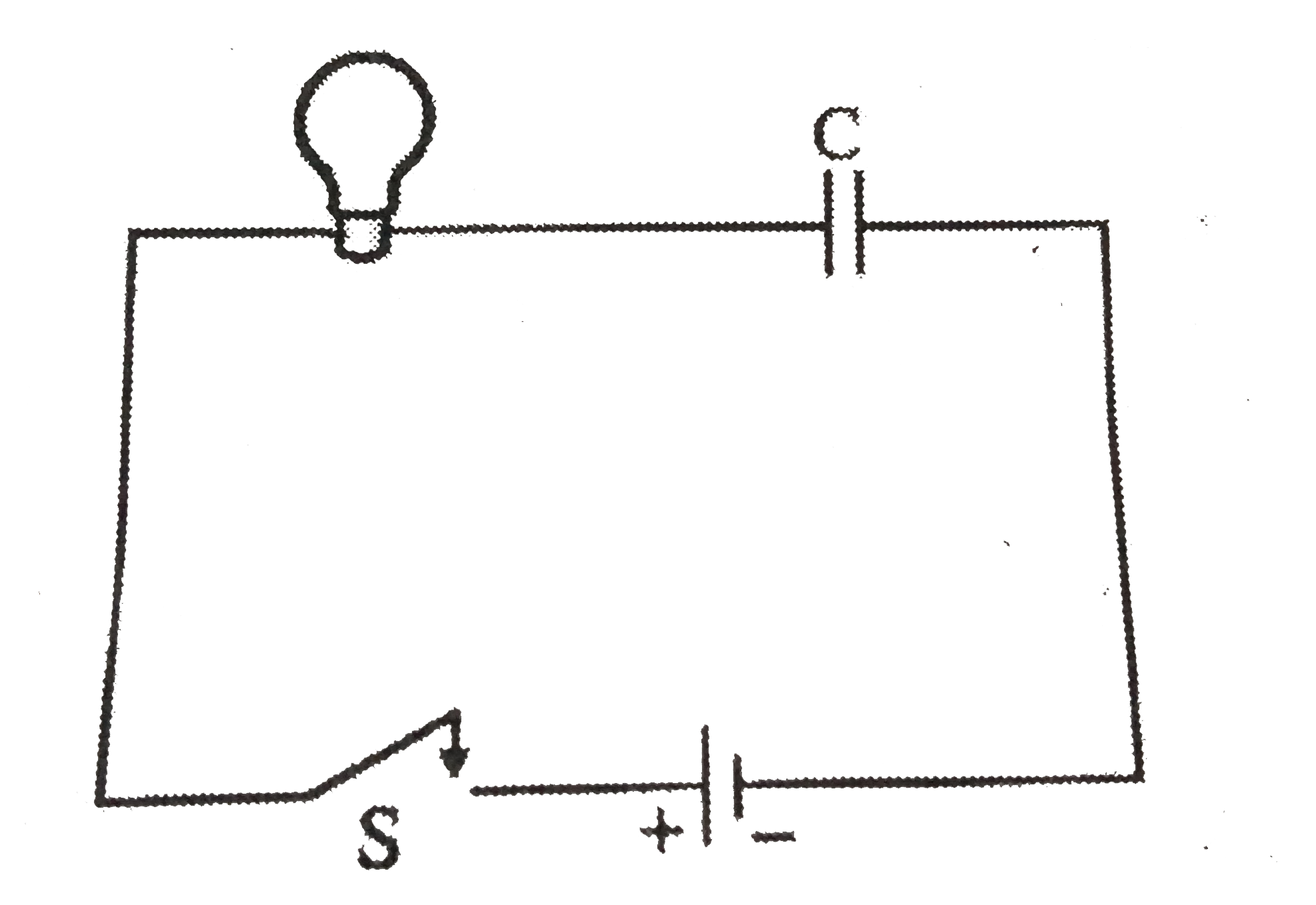
View SolutionA light bulb a capacitor and a battery are connected together as shown in figure, with switch S initially open. When the switch s is closed, which statement is true ?
View Solution

