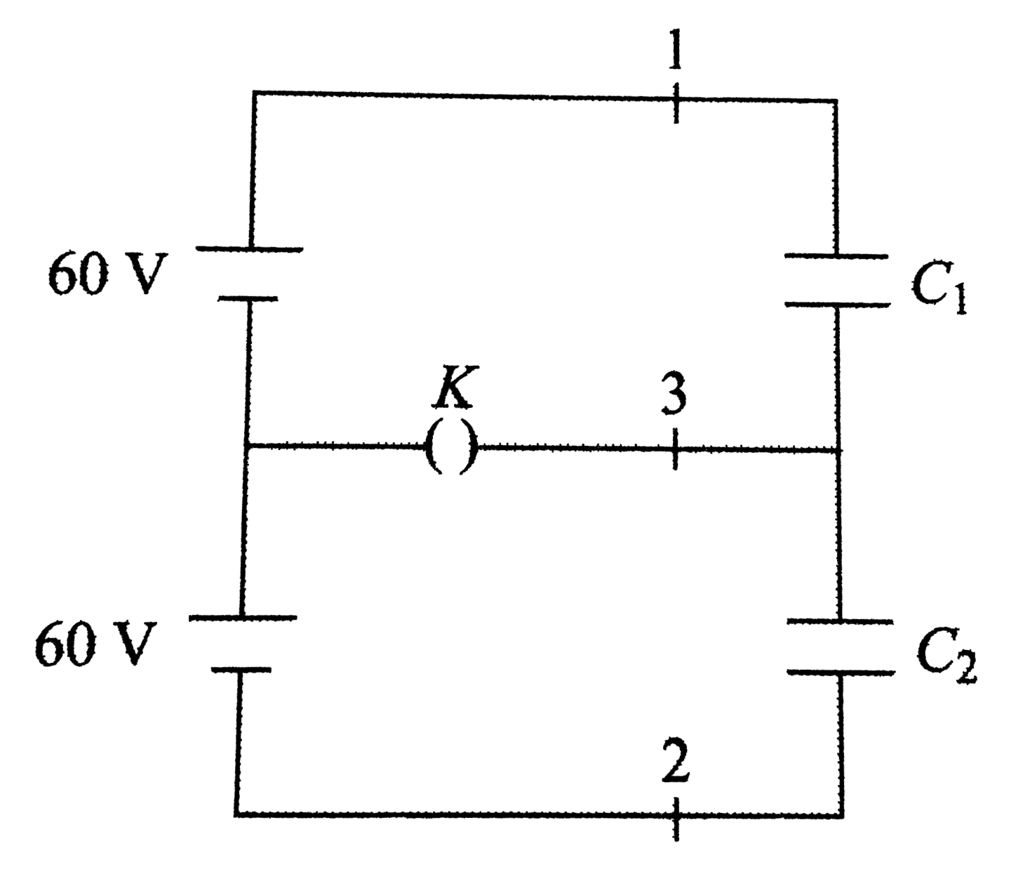
In the circuit shown , the emf of each battery is 60V and C1=2μF and C2=3μF. Find the charges that will flow through the sections 1,2 and 3 after the Key is closed.
 .
.
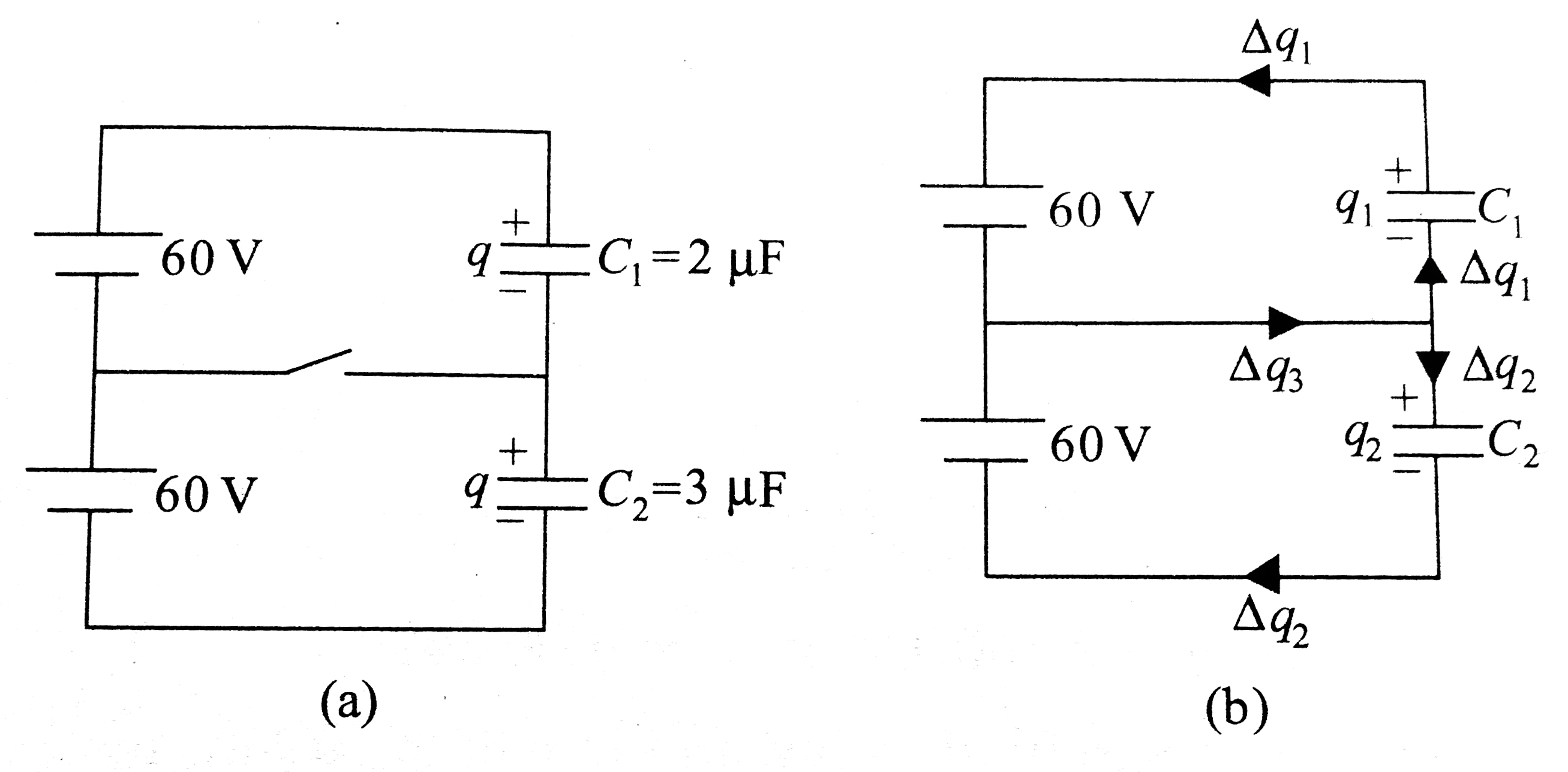
Before closing the switch , both capacitors are in series. Their equivalent capacitance is
Ceq=2×32+3=65μF
 .
.
 .
.
So charge on each capacitor is
q=Ceq×120=65×120=144μC
After closing the switch, the potential difference across each capacitor is 60V. So charge on them are
q1=C1×60=2×60=120μC
q2=C2×60=3×60=180μC
Charge flowing through section 1 is
Δq1=q−q1=144−120=24μC
Charge flowing through section 2 is
Δq2=q2−q=180−144=36μC Charge flowing though dection 3 is
Δq3=Δq1+Δq2=24+36=60μC.
Topper's Solved these Questions
- CAPACITOR AND CAPACITANCEBook:CENGAGE PHYSICSChapter:CAPACITOR AND CAPACITANCEExercise:Exercise 4.1
Explore 13 Videos
- CAPACITOR AND CAPACITANCEBook:CENGAGE PHYSICSChapter:CAPACITOR AND CAPACITANCEExercise:Exercise 4.2
Explore 32 Videos
- CAPACITOR AND CAPACITANCEBook:CENGAGE PHYSICSChapter:CAPACITOR AND CAPACITANCEExercise:Integer
Explore 5 Videos
- ATOMSBook:CENGAGE PHYSICSChapter:ATOMSExercise:QUESTION BANK
Explore 40 Videos
- CENGAGE PHYSICS DPPBook:CENGAGE PHYSICSChapter:CENGAGE PHYSICS DPPExercise:subjective type
Explore 51 Videos
Similar Questions
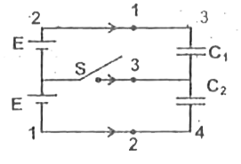
In the circuit shown, the emf of each battery is E. Find the charges that will flow when the switch S is closed, through sections 1, 2 and 3 in the directions indicated by the arrows.
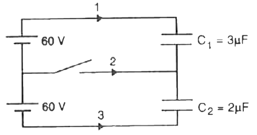
View SolutionIn the circuit shoenin figure 6.17 the emf of each better is 60 V, and the capacitances of the capacitors are C1=3μF and 2μF. Find the charges which will flow after the switch is colosed through the wires 1,2 and 3 n the directions indicated by the arrows.
View Solution
Knowledge Check
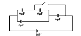
In the circuit shown, find the amount of charge that will flow through the key when it is closed.
 A20μCB40μCC80μCD120μC
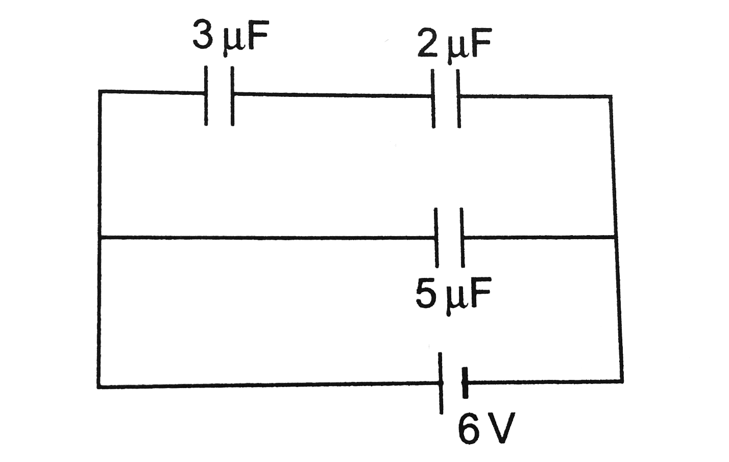
In the circuit shown in figure, the ratio of charge on 5μF and 2μF capacitor is
 A54B53C38Dnone of these
Capacitor C1=2μFandC2=3μF are connected in series to a battery of emf ε=120V whose midpoint is earthed. The wire connecting the capacitors can be earthed through a key K. Now, key K is closed. Determine the charge flowing through the sections 1, 2, and 3 in the directions indicated in figure
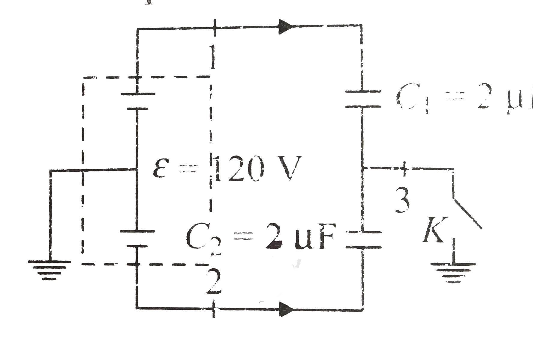
In section 3,A−24μCB−36μCC−60μCD60μC
In the circuit shown the capacitors are C1=15μF,C2=10μFandC3=25μF. Find
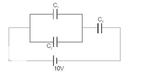
the charge on each capacitor and
View SolutionIn the circuit shown the capacitors are C1=15μF,C2=10μFandC3=25μF. Find
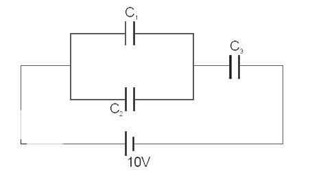
the equivalent capacitance of the circuit.
View SolutionIn the circuit shown the capacitors are C1=15μF,C2=10μFandC3=25μF. Find
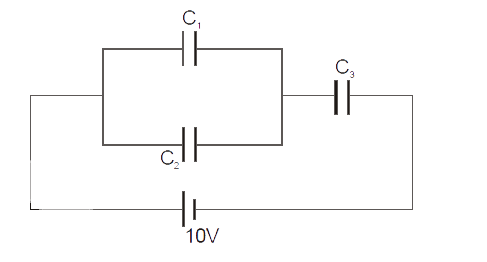
the potential difference across each capacitor.
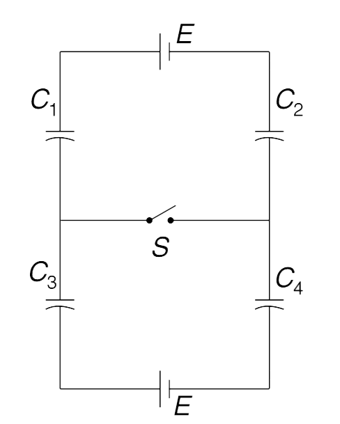
View SolutionIn the circuit shown in Figure E=12V,C1=4μF,C2=2μF,C3=6μFandC4=3μF
Find the heat produced in the circuit after switch S is shorted.
View SolutionA capacitor of capacitance C1=1.0μF charged up to a voltage V=110V is connected in parallel to the teminals of a circuit consisting of two uncharged capacitors connected in series and possessing the capacitances Cs=2.0μF and Cs=3.0μF. What charge will flow through the connecting wires ?
View Solution

