To get an output 1 from the circuit shown in the figure, the input must be 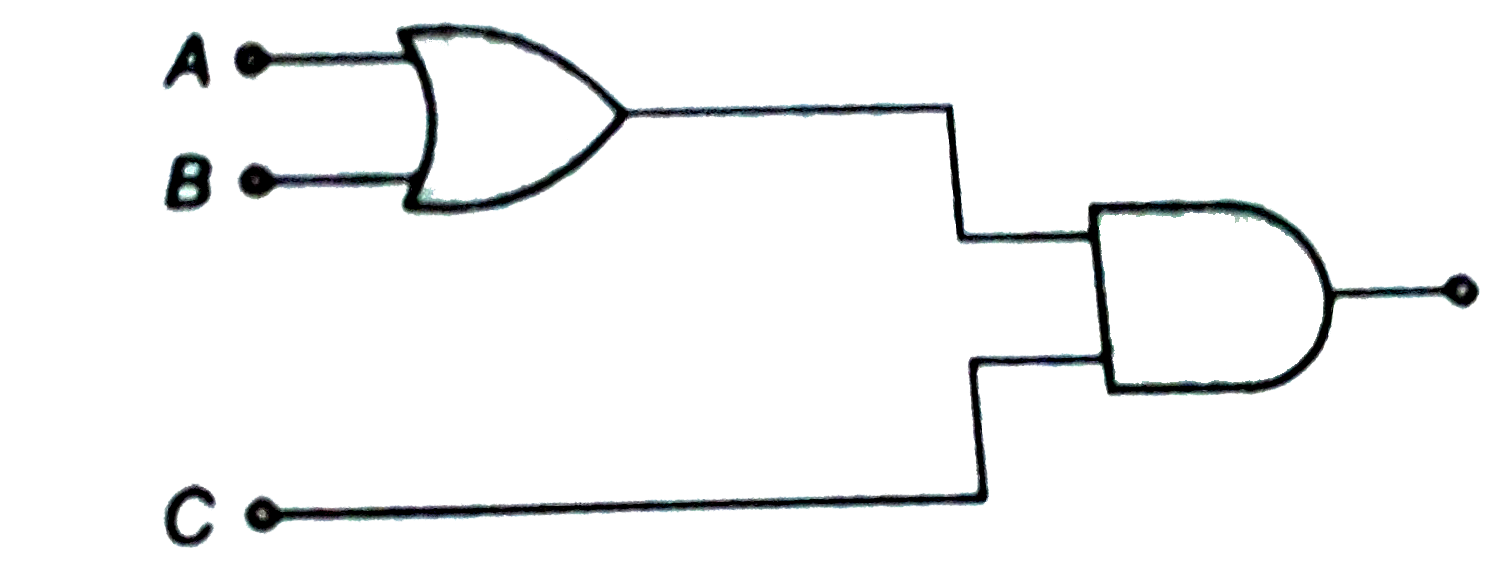
A
B
C
D
Video Solution
Text Solution
The correct Answer is:C
We can realize the gate circuit as
 <math xmlns=) 1,Y_(1)=A+B2, Y_(2)=Y_(1)*C=(A+B)CA=0, B=1, C=0Y_(2)=(0+1).0=1.0=0 A=1, B=0, C=0Y_(2)=(1+0).0=0A=1, B=0, C=1Y_(2)=(1+0).1=1.1=1A=1, B=1, C=0Y_(2) =(1+1).0=1.0=0
1,Y_(1)=A+B2, Y_(2)=Y_(1)*C=(A+B)CA=0, B=1, C=0Y_(2)=(0+1).0=1.0=0 A=1, B=0, C=0Y_(2)=(1+0).0=0A=1, B=0, C=1Y_(2)=(1+0).1=1.1=1A=1, B=1, C=0Y_(2) =(1+1).0=1.0=0
|
Topper's Solved these Questions
- SEMICONDUCTORSBook:MHTCET PREVIOUS YEAR PAPERS AND PRACTICE PAPERSChapter:SEMICONDUCTORSExercise:Exercise 1 ( MISCELLANEOUS PROBLEMS )
Explore 33 Videos
- SEMICONDUCTORSBook:MHTCET PREVIOUS YEAR PAPERS AND PRACTICE PAPERSChapter:SEMICONDUCTORSExercise:MHT CET Corner
Explore 25 Videos
- SEMICONDUCTORSBook:MHTCET PREVIOUS YEAR PAPERS AND PRACTICE PAPERSChapter:SEMICONDUCTORSExercise:MHT CET Corner
Explore 25 Videos
- SCALARS AND VECTORS Book:MHTCET PREVIOUS YEAR PAPERS AND PRACTICE PAPERSChapter:SCALARS AND VECTORS Exercise:Exercise 2 (Miscellaneous Problems)
Explore 20 Videos
- STATIONARY WAVES Book:MHTCET PREVIOUS YEAR PAPERS AND PRACTICE PAPERSChapter:STATIONARY WAVES Exercise:MHT CET Corner
Explore 28 Videos
Similar Questions
Knowledge Check
To get an output of 1 form the circuit shown in figure the input must be :-
_E01_514_Q01.png) Aa=1,b=0,c=1Ba=1,b=1,c=0Ca=0,b=1,c=0Da=0,b=0,c=1
Aa=1,b=0,c=1Ba=1,b=1,c=0Ca=0,b=1,c=0Da=0,b=0,c=1To get an output y=1 from the circuit shown below, the input must be
 AABC010BABC001CABC101DABC100
In order to obtain an output Y=1 form the circuit of fig. the inputs must be
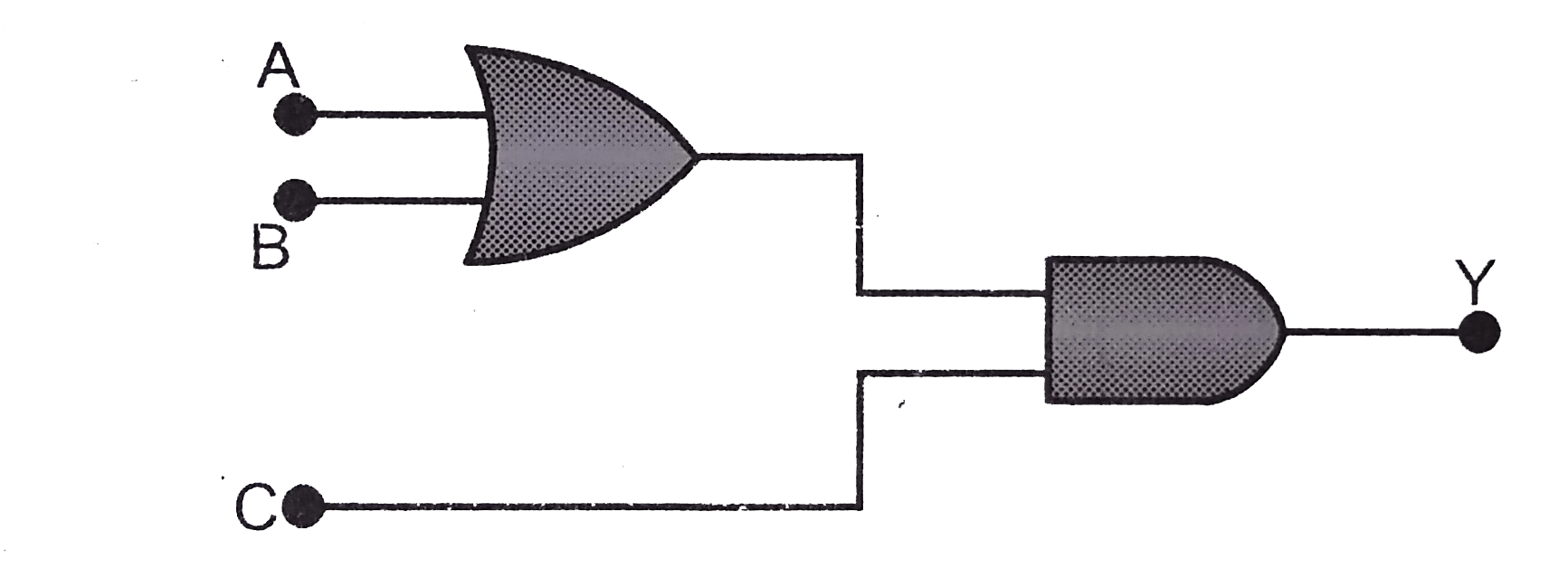 AABC010BABC100CABC100DABC110
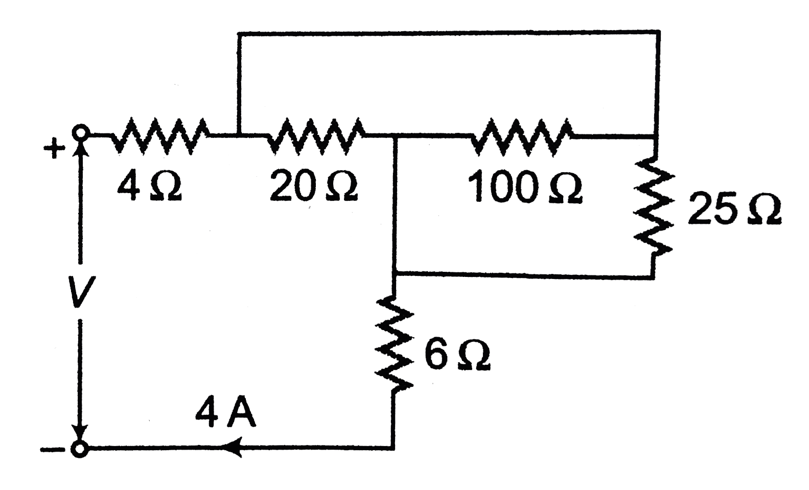
In the circuit shown in the figure , V must be -
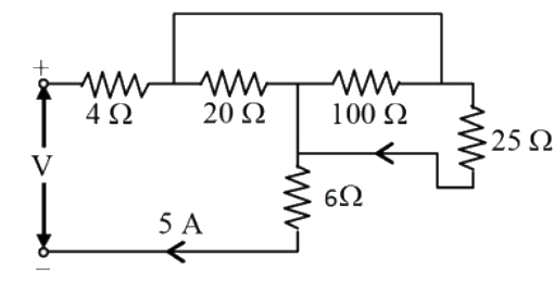
View SolutionTo get an output 1 from the circuit shown in figure the input must be :

View SolutionThe output Y of the gate circuit shown in the figure below is

View SolutionThe output Y of the gate circuit shown in the figure below is

View SolutionIn the circuit shown in figure , V must be
View Solution
