Figure (EP) shows a communication system. What is the output power when input signals is of 1.01 mW? [ gain in dB=10log10(P0/Pt)].
![Figure (EP) shows a communication system. What is the output power when input signals is of 1.01 mW? [ gain in dB = 10 log10(P0//Pt)].](https://d10lpgp6xz60nq.cloudfront.net/physics_images/PR_XII_V02_C10_S01_242_Q01.png)
90mW
101mW
1112mW
120mW
The correct Answer is:B

Here, transmission path =5km
Loss suffered in transmission path
=−2dBkm−1×5km=−10dB
Total amplifier gain =10dB+20dB=3 0dB
Overall gain of singal =30dB-10dB=20dB
As, gain in dB=10log10(P0Pi):∴20=10log10(P0Pi)
or log10(P0Pi)=2010=2=log10100 or P0Pi=100
or P0=Pi×100=1.01mW×100=101mW
Topper's Solved these Questions
- COMMUNITCATION SYSTEMSBook:NCERT FINGERTIPSChapter:COMMUNITCATION SYSTEMSExercise:HOTS
Explore 10 Videos
- COMMUNITCATION SYSTEMSBook:NCERT FINGERTIPSChapter:COMMUNITCATION SYSTEMSExercise:Assertion And Reason
Explore 30 Videos
- ATOMS Book:NCERT FINGERTIPSChapter:ATOMS Exercise:Assertion And Reason
Explore 15 Videos
- CURRENT ELECTRICITYBook:NCERT FINGERTIPSChapter:CURRENT ELECTRICITYExercise:Assertion And Reason
Explore 15 Videos
Similar Questions
Knowledge Check
A 1KW signal is transmitted using a communication channel which provides attenuatiom at the rate of −2dBperkm . If the communication channel has a total length of 5km , the power of the signal received is
[ gain in dB=10log(P0Pi)]A900WB100WC990WD1010WWhat is the output Y in the following circuit, when all the three output A,B,C are first 0 and then 1?
 A1,0B1,1C0,1D0,0
In a common emitter amplifier, using output reisistance of 5000 ohm and input resistance fo 2000ohm, if the peak value of input signal voltage is 10mV and β=50. The power gain is
A125×50B12590C1.25×50D2.5×104
A signal of 0.1 kW is transmitted in a cable. The attenuation of cable is -5 dB per km and cable length is 20 km. The power received at receiver is 10−x W. The value of x is _____ . [Gain in 10log10(P0Pi) ]
View SolutionThe circuit diagram (see fig.) shows a 'logic combination' with the states outputs X,Y and Z given for input P,Q,R and S all at state 1 (i.e., high). When inputs P and R change to state 0 i.e., low) with inputs Q and S still at 1, the condition of output X,Y and Z chages to
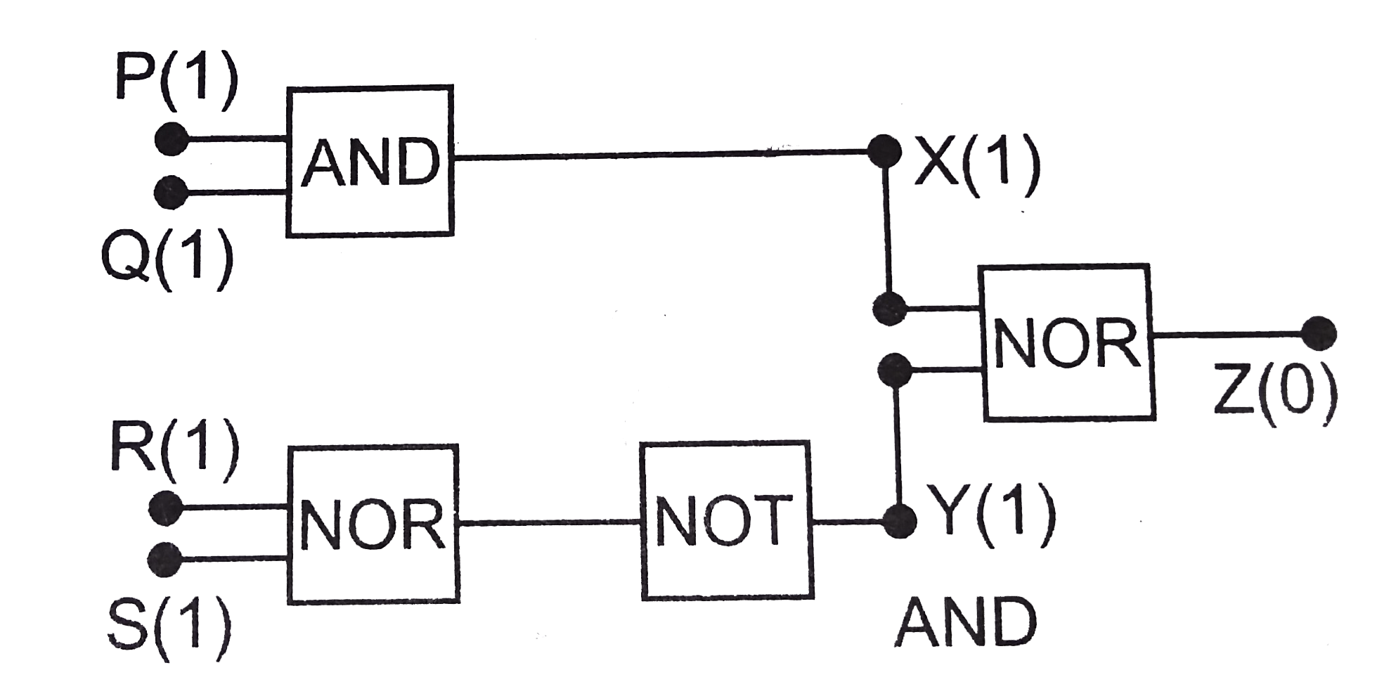
View Solution
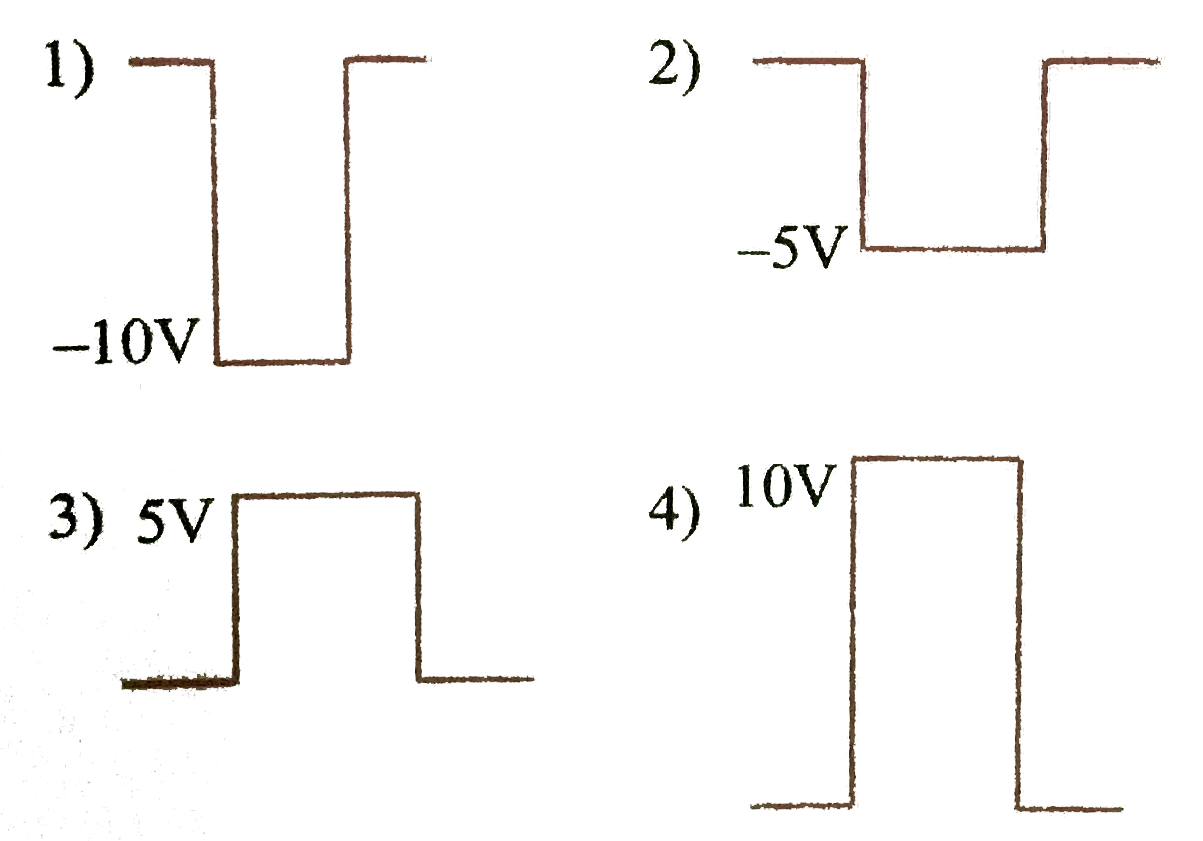
In p-n junction diode a square input signal of 10 V is applied as shown in figure The output signal across RL will be
View Solution
In p-n junction diode a square input signal of 10 V is applied as shown in figure The output signal across RL will be
View SolutionIf in a p−n junction diode , a square input single of 10V is applied as shown
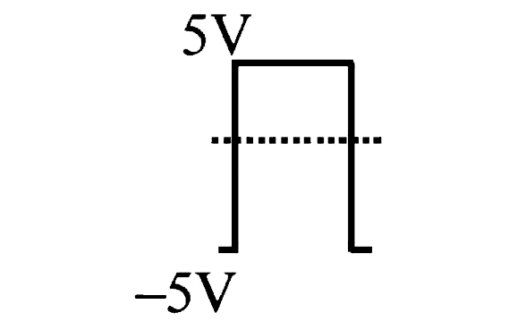
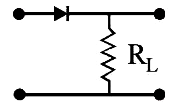
View Solution


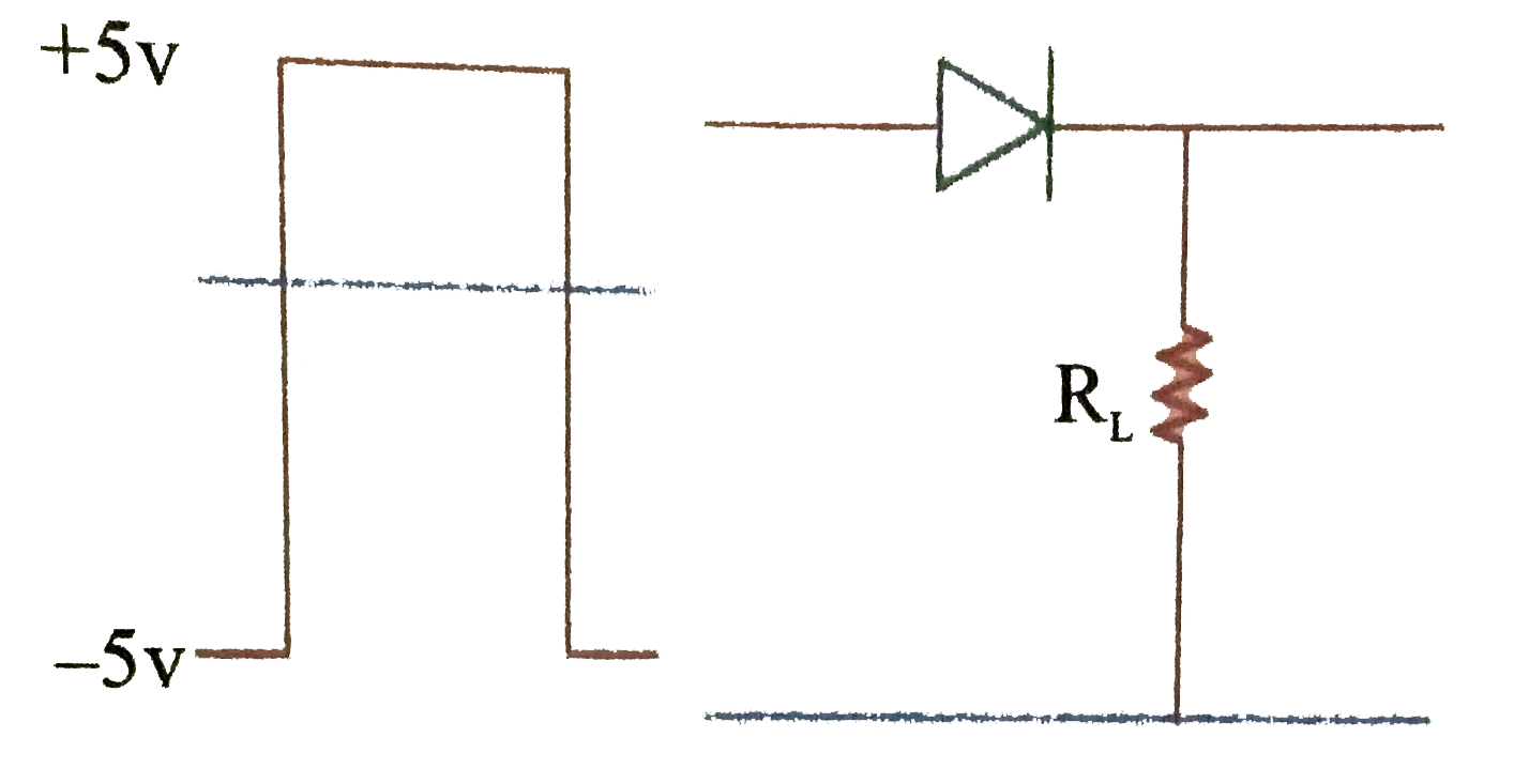
 .
.