Doubtnut Promotions Sticky

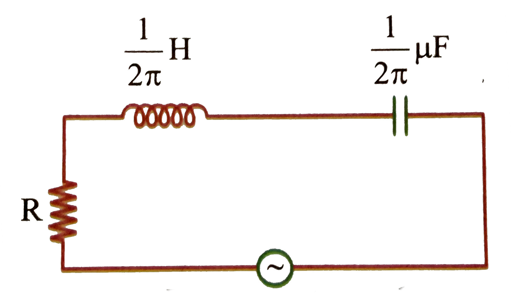
In a LCR series resonating circuit. Give the value of average power loss.

Video Solution
Doubtnut Promotions Banner
Text Solution
Verified by Experts

Average power loss
<P>=Vrms.cosop=Vrms.IrmsRR2+(XLXC)2

|
Updated on:21/07/2023

Related Playlists


Knowledge Check

  • Question 1 - Select One

    In series resonant circuit, at resonance,

    AZ=R2+(XLXC)2
    BZ=XLXC
    CZ=R
    DZ=XC
  • Question 1 - Select One

    In an LCR circuit, at resonance

    Athe current is minimum
    Bthe current and voltage are in phase
    Cthe current leads the voltage by π/2
    Dthe impedence is maximum
  • Question 1 - Select One

    In a series resonant L-C-R circuit, the power factor is

    A0
    B1
    C0.3
    D1.5
  • Question 1 - Select One

    In an LCR series circuit the current is

    Ain phase with applied emf
    Blags the applied voltage
    Clead the applied voltage
    Dmay lead or lag behind the applied voltage
  • Question 1 - Select One or More

    In LCR circuit during resonance

    Apower factor is zero
    Bpower factor is one
    Cpower developed acrtoss resistance is zero
    Dpower developed across capacitance is zero
  • Question 1 - Select One

    Assertion : In series LCR resonance circuit, the impedance is equal to the ohmic resistance.
    Reason : At resonance, the inductive reactance exceeds the capacitive reactance.

    AA
    BB
    CC
    DD
  • Question 1 - Select One

    Assertion : In series LCR resonance circuit, the impedance is equal to the ohmic resistance.
    Reason : At resonance, the inductive reactance exceeds the capacitive reactance.

    AIf both assertion ans reason are true ans reaason is the correct explanation of assertion.
    BIf both assertion and reason are true but reason is not the correct explanation of assertion.
    CIf assertion istrue but reason is false.
    DIf both assertion and reason are false.
  • Question 1 - Select One

    In a series LCR circuit
    ocr_image

    Athe voltage VL across the inductance leads the current in the circuit by a phase angle of π/2
    Bthe voltage VC across the capacitance lags behind the current by a phase angle of π/2
    Cthe voltage VR across the resistance is in phase with the current
    Dthe voltage across sereis combination of L, C and R is V=VL+VC+VR

Similar Questions