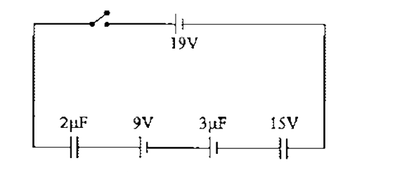
Assertion : Two capacitors are charged from the same battery nd then connected as shown. A current will flow i ntil clock direction as soon as switch is closed.
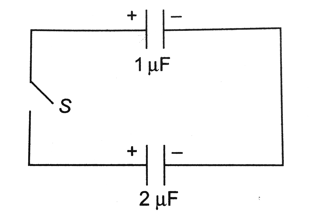
Reason: In steady state charges on two capacitors are in the ratio 1:2.
If both Assertion and Reason are true and the Reason is correct explanation of the Assertion.
If both Assertion and Reason are true but Reason is not the correct explanation of Assertion.
If Assertion is true, but the Reason is false.
If Assertion is false but the Reason is true.
The correct Answer is:D
Charge (or current) will not flow in the circuit as they have already the same potential, which is a condition of parallel grouping
Further,
q1q2=C1VC2V=C1C2=12
Topper's Solved these Questions
- CAPACITORSBOOK - DC PANDEYCHAPTER - CAPACITORSEXERCISE - OBJECTIVE_TYPE
1 Video
- CAPACITORSBOOK - DC PANDEYCHAPTER - CAPACITORSEXERCISE - OBJECTIVE_TYPE
1 Video
- ATOMSBOOK - DC PANDEYCHAPTER - ATOMSEXERCISE - MEDICAL ENTRANCES GALLERY
42 Videos
- COMMUNICATION SYSTEMBOOK - DC PANDEYCHAPTER - COMMUNICATION SYSTEMEXERCISE - Subjective
11 Videos
Similar Questions
Find whether the following statements are true or false.
a. If a battery is connected across a circuit consisting of two identical capacitors, it is found that, in steady state, the two capacitors must be in series with each other.
b. If a battry is connected across a ciruit consisting of two capacitors having differnt capacitances, it is found that, in steady state, the two capacitors has equal charge, then two capacitors must be in seties with each other.
c. If a battery is connected across a circuit cansisting of two identical capacitors, it is found that, in steady state, the two capacitors have equal charge, then the two capacitors may be in series with each other.
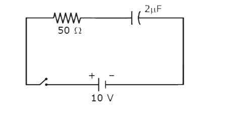
View SolutionFor the circuit shown in figure below, At t = 0, switch is closed, the initial current through resistor and final charge on capacitor are
View Solution
Knowledge Check
In given circuit, switch S is closed at t=0 . The charge on the capacitor ar steady state will be
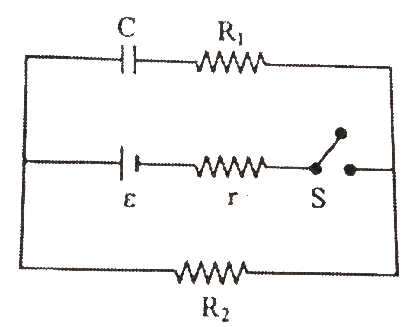 ACεR1r+R1BCεR2r+R2CCεR2r+R1DCεR1r+R2
Six capacitors each of capacitance 1μF are connected as show in . Find the charge flowing in direction 1 as shown in the figure will be
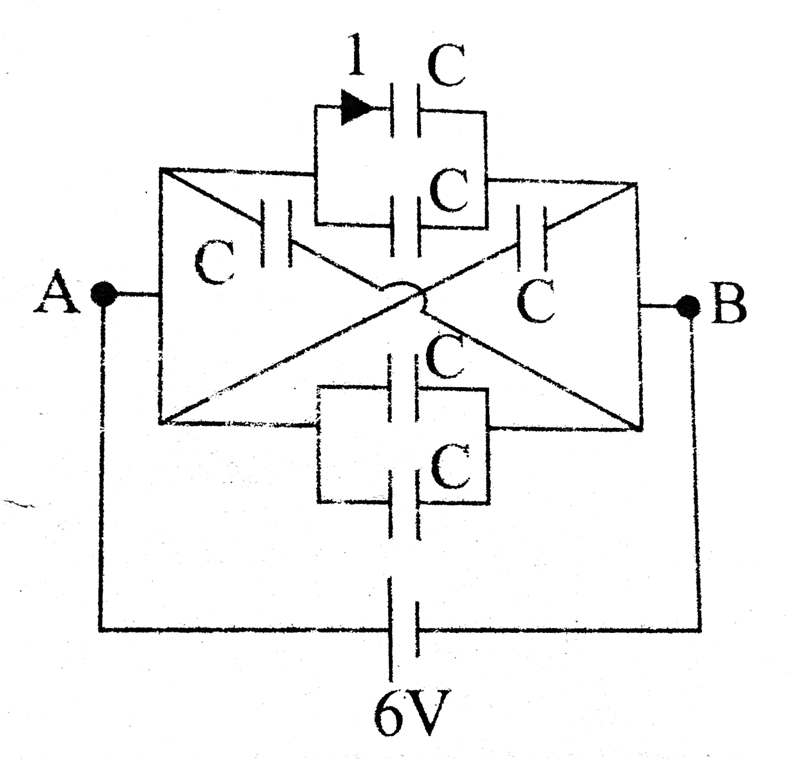 .A12μFB6μFC3μFDnone of these
Four capacitors of capacitance 10μF and a battery of 200V are arranged as shown. How much charge will flow through AB after the switch S is closed :
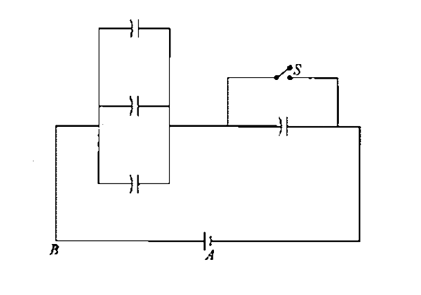 A6000μCB4500μCC3000μCD4000μC
A capacitor of 8 F is connected as shown in the figure. At steady state Charge on the plates of the capacitor
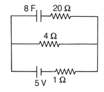
View SolutionTwo capacitorsC1andC2=2C1 are connected in a circuit with a switch between them as showu in the figure- 3.302. Initially the switch is open and C1 holds charge Q. The switch is closed. In steady state, the charge on the two capacitors will be given as :
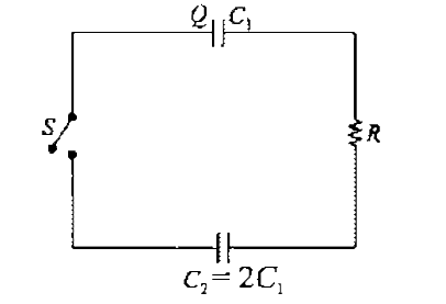
View SolutionAssertion: Two capacitors are connected in series with a battery. Energy stored across then is in inverse ratio of their capacity.
Reason: U=12qV or U∝qV
View SolutionTwo capacitors of capacity 6μF and 3μF are charge 100V and 50V separately and connected as shown in Now all the three switches S1,S2, and S3 are closed.
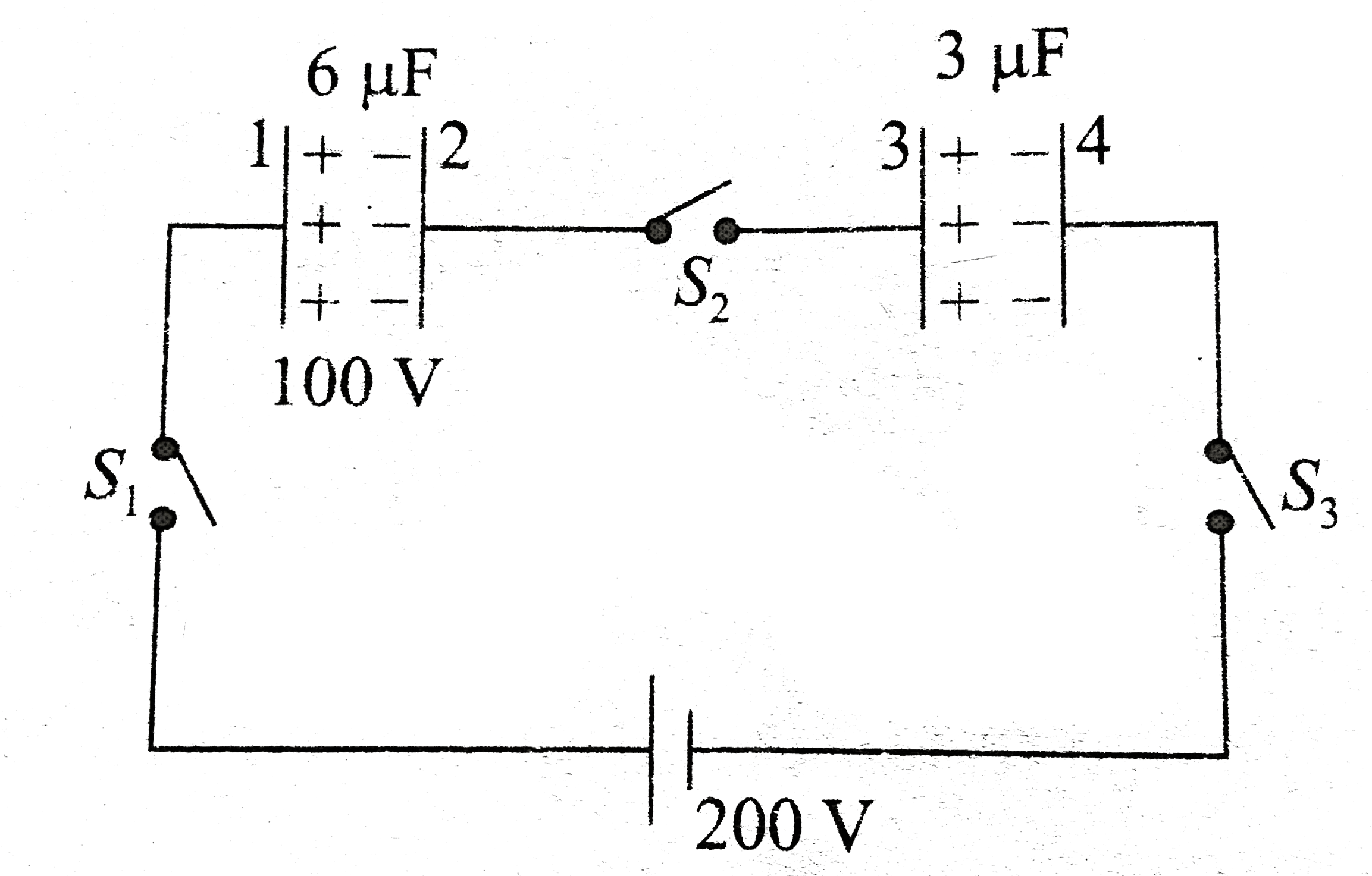
Charge on the 3μF capacitor in steady state willl be.
View SolutionThe two capacitors in the circuit shown in figure are initially uncharged and then connected as shown and switch is closed. What is the potential difference across 3μF capacitor?
View Solution