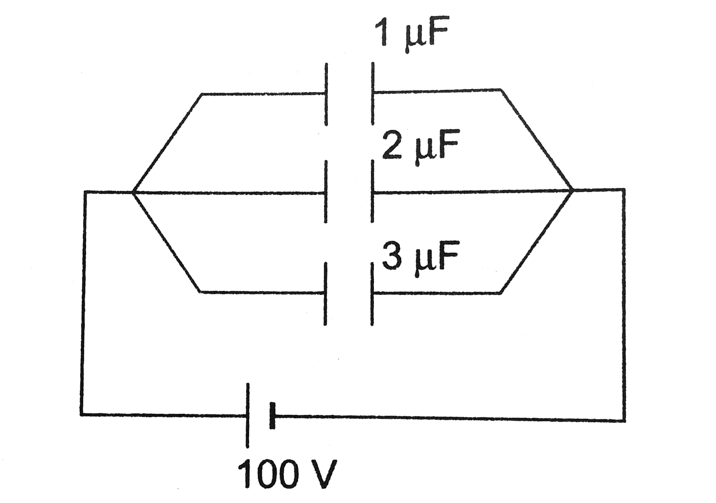
In the circuit shown in figure find
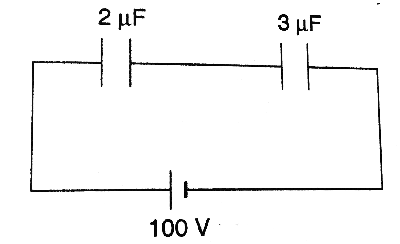
a. the equivalent capacitance
b. the charge stored in each capacitor and
c. the potential difference across each capacitor.
1.2μF 120μC 60Vand40V
1.2μF 120μC 60Vand20V
1.2μF 12μC 60Vand40V
12μF 120μC 60Vand40V
The correct Answer is:A
a. The equivalent capacitance
C=C1C2C1+C2
or C=(2)(3)2+3=1.2μF
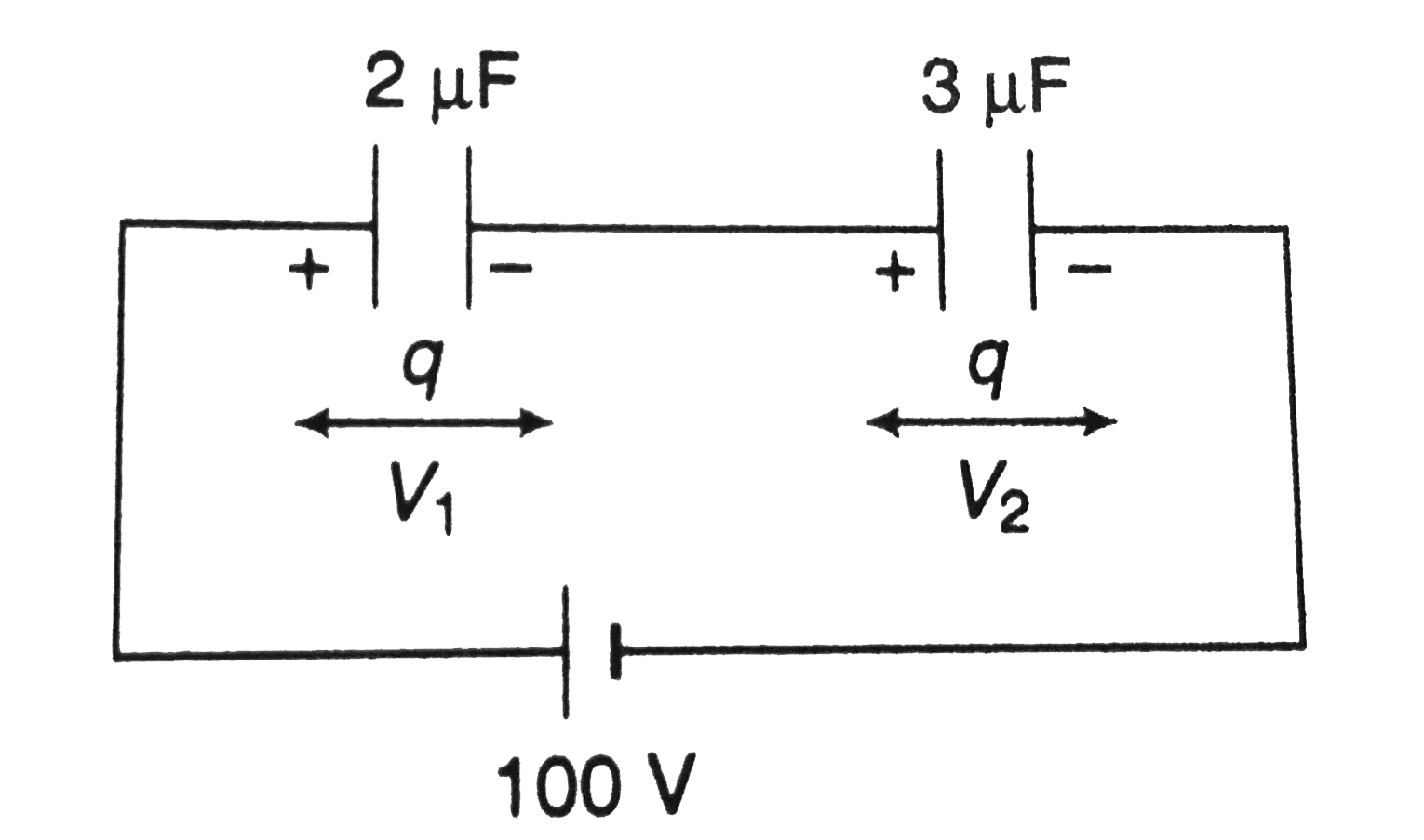
b. The charge q stored in each capacitor is
q=CV=(1.2×10⁻⁶)(100)C
=120μC
c. In series combination V∝1CorV1V2=C2C1
∴V1=(C2C1+C2)V+(32+3)(100)=60V
andV2=V−V1=100−60=40V ltbr In parallel
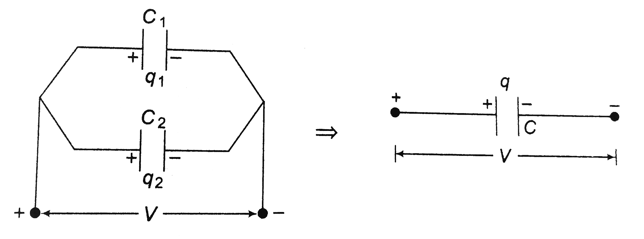
the arrangement shown in figure is called a paralel connection. In a parallel combination the potential difference for all individual capacitors is the same and the total charge q is distributed in the ratio of the capacities. (asq=CV or q∝C for same potential difference). Thus,
q1q2=C1C2
or q1=(C1C1+C2)qandq2=(C2C1+C2)q
The parallel combination is equivalent to a single capacitor with the same total charge q=q1+q2 and potential difference V.
Thus,
q=q1+q2
or CV=C1+C2V
or C=C1+C2
In the same way, we can show that for any number of capacitors in parallel
C=C−1+C2+C3+..........
In a parallel combination the equilavent capacitance is always greater than any individual capacitance.
Topper's Solved these Questions
- CAPACITORSBook:DC PANDEYChapter:CAPACITORSExercise:Exercise
Explore 155 Videos
- CAPACITORSBook:DC PANDEYChapter:CAPACITORSExercise:OBJECTIVE_TYPE
Explore 1 Video
- ATOMSBook:DC PANDEYChapter:ATOMSExercise:MEDICAL ENTRANCES GALLERY
Explore 42 Videos
- COMMUNICATION SYSTEMBook:DC PANDEYChapter:COMMUNICATION SYSTEMExercise:Subjective
Explore 11 Videos
Similar Questions
Knowledge Check
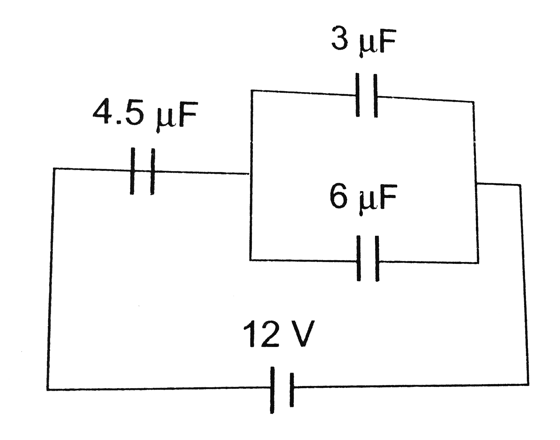
In the circuit shown in the figure, the potential difference across the 4.5μF capacitor is
 A83voltsB4 voltsC6 voltsD8 volts
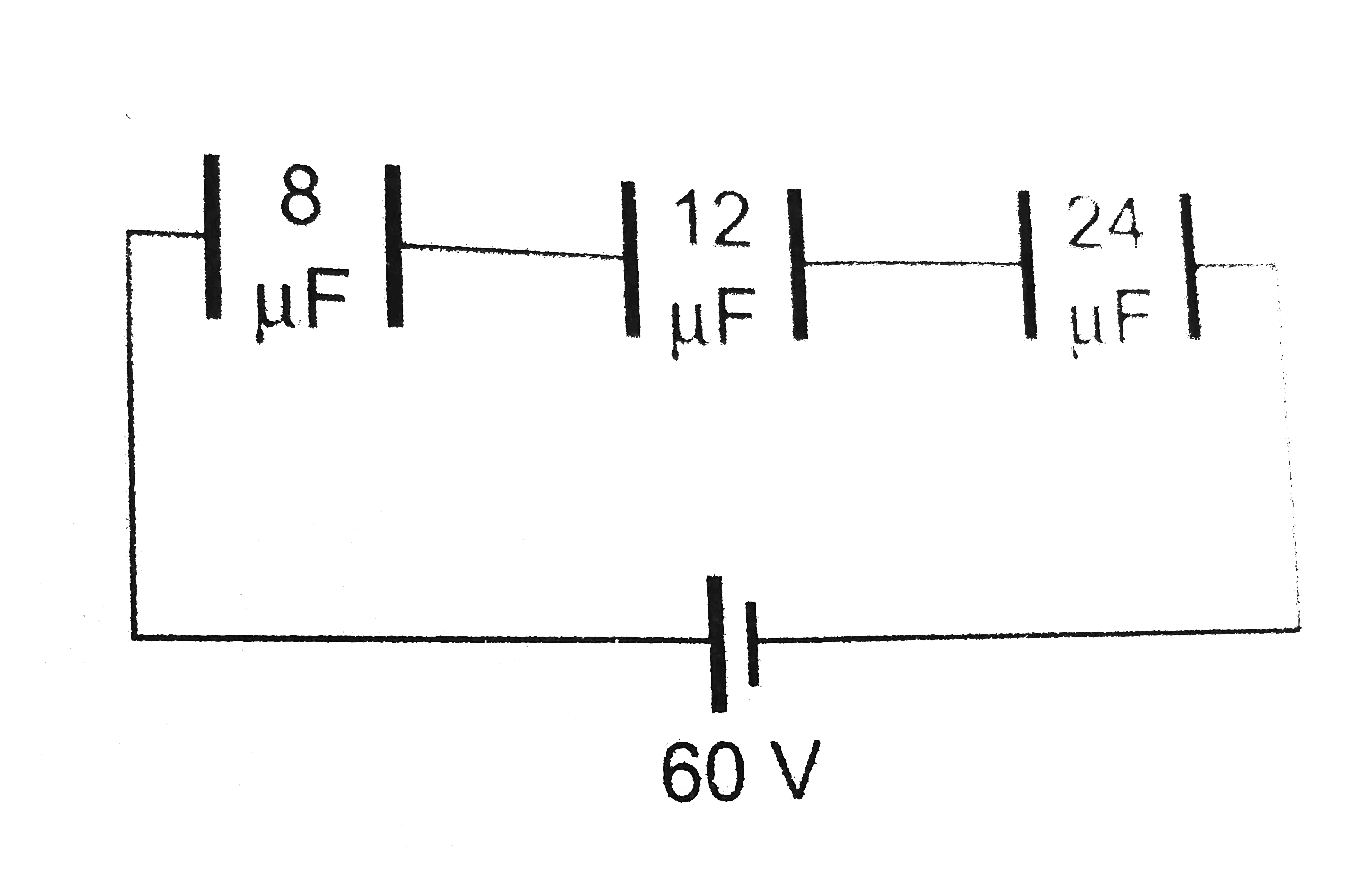
Find the potential difference and charge on each capacitor.
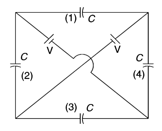
View SolutionIn the circuit shown in the figure, find charge on each capacitor.
View Solution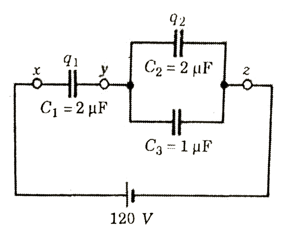
find the charges on the capacitors in figure. And the potential differences across them.
View SolutionIn the circuit shown the capacitors areC1=15μF,C2=10μFandC2=25μF.Find
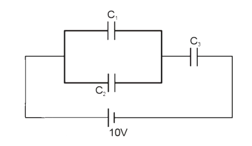
(i) The equivalent capacitance of the circuit
(ii) The charge on each capacitor and
(iii) The potential difference a across each capacitor.
View SolutionIn the circuit shown in figure
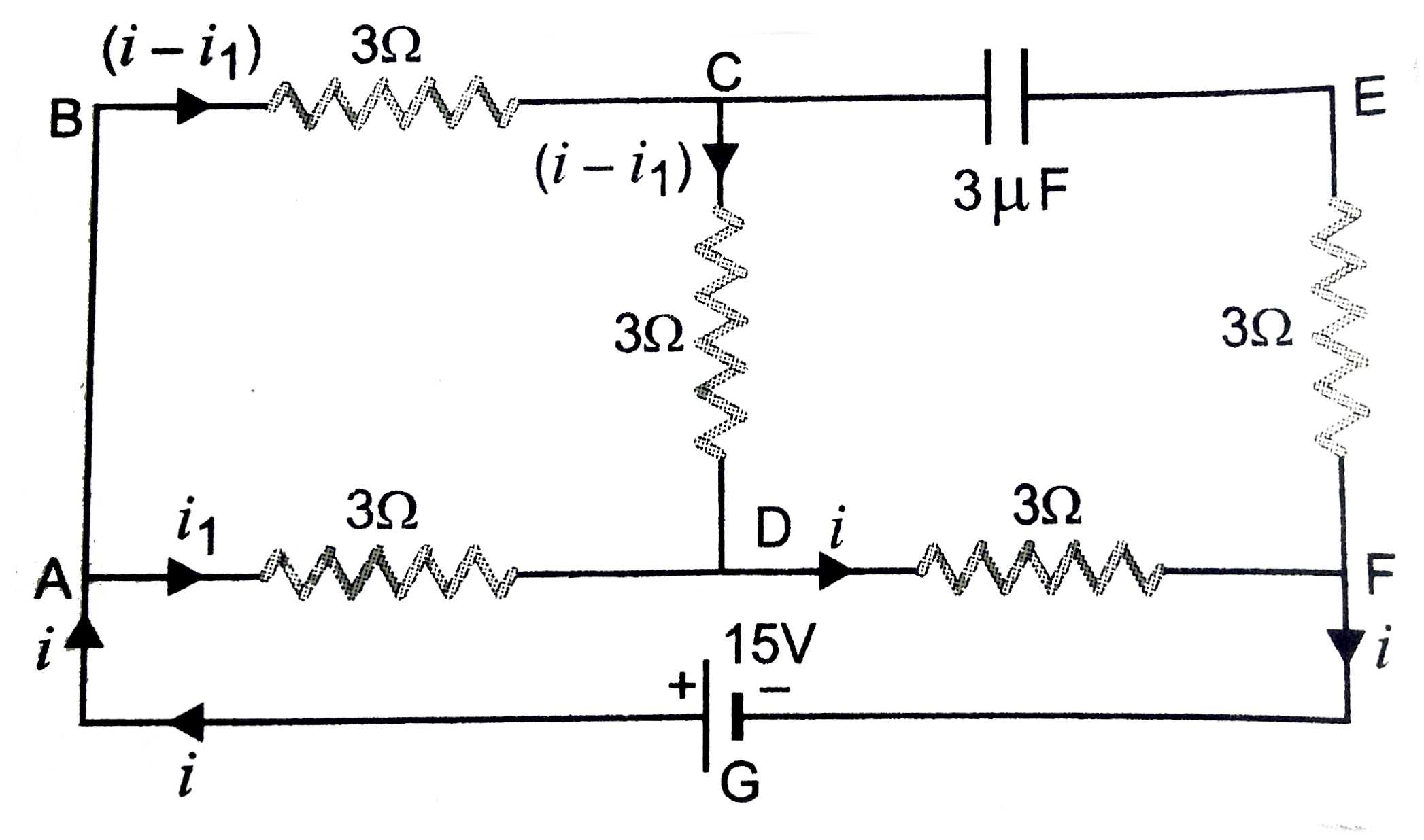
Find the potential differnece across capacitor.
View SolutionIn figure C1=C5=8.4μF and C2=C3=C4=4.2μF.The applied potential is Vab=220V
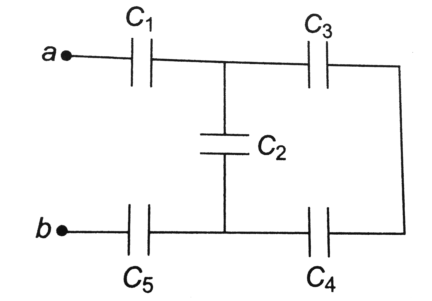
(a) What is the equivalent capacitance of the network between points a and b?
(b) Calculate the charge on each capacitor and the potential difference across each capacitor.
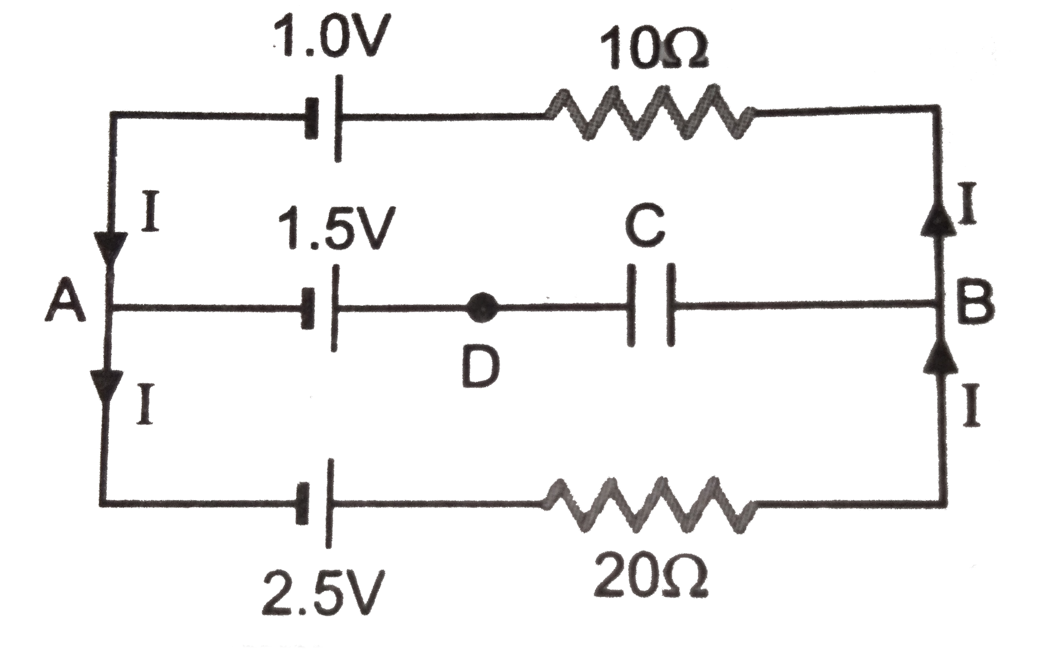
View SolutionIn the circuit diagram find the potential difference across the plates of capacitor C
View Solution


