MOVING CHARGES AND MAGNETISM for Class 12 PHYSICS
INTRODUCTION
Bachho aapne magnet to bachpan me dekha hi hoga jisse lohe ki bani chije attract hoti hai. Magnet me aisa kya hai ki iron se bani chijo ko attract karta hai? Aur magnet ko magnet kyu bolte hai? Ancient time me jab khudai ki gai to khudai me stone nikale. Ye stone iron oxide the jisko magnetite kaha gaya. Ager in stones ko hum kisi dhage se bandh kr latka dete hai to ye stones ek particular direction me ruk jate hai. Isse ye pta chala ki in stones me kuchh to properties hai jiske karan ye magnetites dusre magnetites ya iron ko apni taraf attract and repel bhi karte hai means do bodies bina touch huye ek dusre pr force apply kr rahe hai, ise field force kahte hai. Abhi tak humne gravitational force aur electrostatic force ke baare me padha hai jisme se gravitational force do mass ke bich lagane wala force hai aur electrostatic force do charge ke bich lagane wala force hai. But yaha pr magnetites, mass to hai but ye hr dusre mass ko attract nahi karte balki kevel iron aur iron se bani chijo ko attract karte hai; iska mtlb hai ye koi tisre type ka force hai joki gravitational force aur electrostatics force se alag hai jo magnetic force kehlata hai. Magnetite ki wajah se ye jo special property thi isko humne nam diya magnet.
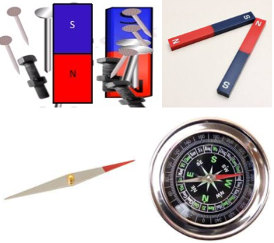

CONCEPT OF MAGNETIC FIELD
Magnetic field wo area hota hai jaha pr kisi magnets ki wajah se ek field bn jata hai, jiska effect is magnet ke aaspaas hota hai. Effect Kaise mahsus karenge? Maan lo ki kisi lohe ke tukde ko kisi magnet ke aaspaas le jane se ager ye tukda attract hota hai means isme force lagta hai to aap samjh jayenge ki ye magnetic field hai. The space around the magnet within which its influenced is called its magnetic field. Wo space jaha tak kisi magnet ki existence ya presence feel kiya ja sake use magnetic field kahte hai. Magnetic field ek vector quantity hai jiska symbol B aur SI unit tesla hai.
- The source of the magnetic field is moving charges. Jab hum pre existing field me koi charge le jate hai to usme magnetic force apply hone lagta hai.
Oersted experiment
Ek current carrying conductor ke pass magnetic compass rakhe, jaise hi current conductor se flow hua compass me deflection hua. Magnetic compass tabhi deflect hota hai jab uske aaspaas magnetic field present ho kyuki yahi compass pr force lagata hai aur deflection aata hai. Iska mtlb hai ager conductor me current flow karane ke baad hi magnetic deflection hua mtlb current ke flow se hi magnetic field conductor ke around create hua. Jab current flow karna band kr de to deflection zero ho jata hai. Iske alawa ager current ko opposite direction me flow karaye to magnetic compass me deflection dusre direction me ho jata hai.Magnetic compass me deflection dene wala koi aur nahi balki current hi hai. Jisko different diection me flow karne pr compass me deflection different direction me show karta hai kyuki current high magnetic field bana raha hai.
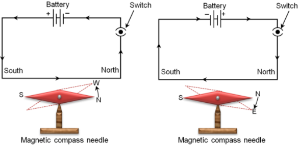
Conclusion - Oersted ke is experiment se hume conclusion ye mila ki current carrying conductor hi magnetic field banata hai ya produce karta hai.
- Current carrying conductor produces a magnetic field.
1. A current or a moving charge creates a magnetic field in the surrounding space (in addition to its electric field).
2. The magnetic field exerts a force on any other moving charge or current that is present in the field.
MAGNETIC FORCE
Jab kisi magnet ke magnetic field me iron ya magnetic material ko le jane se inme jo attraction or repultion force lgta hai yahi magnetic force hai.Sources and fields
Magnetic force ke source hai- magnet and moving charges. In magnetic force ke sources ke surrounding me jaha tak magnetic force ko feel kr sakte hai wo area in sources ka magnetic field hai. The concept of a field was specially stressed by Faraday and was incorporated by Maxwell in his unification of electricity and magnetism.Ager moving charges ke karan magnetic field create ho raha hai to is magnetic field me kisi particular point pr ye field ek ya ek se jyada moving charges ke karan ho sakta hai. Jab more charges ke karan us particular point pr field hai to ye field hr ek charges ke karan fields ko vectorially add karke find kiya jata hai jo principle of superposition kehlata hai. The field at a particular point can be due to one or more charges. If there are more charges the fields add vectorially. You have already learnt; this is called the principle of superposition.
Properties of magnetic field
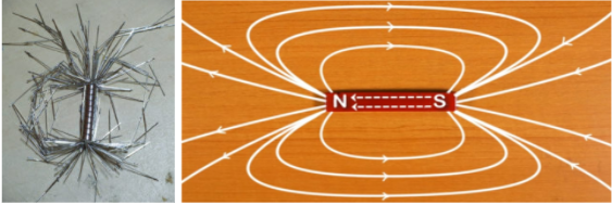
* Magnetic field lines ek aisi imaginary lines hai jisme tangent dal de to ye magnetic field ki direction ko batati hai.* Magnetic field lines humesha closed loop banati hai.
* Magnetic field lines magnet ke bahar humesha north se south ki taraf jati hai aur magnet ke ander south se north jati hai.
* Magnetic field lines kabhi ek dusre ko intersect nahi karti kyuki ager cross ki to intersection point pe ye tangent ho jayegi jo possible nahi hai.
* Magnetic field lines ki density hume lines ki intensity define karti hai, jaha pr magnetic field lines pass-pass hai waha strong magnetic field aur jaha magnetic field lines dur-dur honge waha weak magnetic field hota hai.
Magnetic Field, Lorentz Force
Jab hum kevel Lorentz force ki baat karte hai to ye force electric aur magnetic dono force ke karan hota hai. Ager kisi aise region me charge particle move karta hai jaha electric aur magnetic dono field present ho waha ye charge particle jo total force experience karta hai wahi Lorentz force kehlata hai. The total force experienced by a charged particle moving in a region where both electric and magnetic fields are present, called Lorentz force.Electric field me koi charge q electric force (→Fe) experience karta hai.
→Fe=q→E
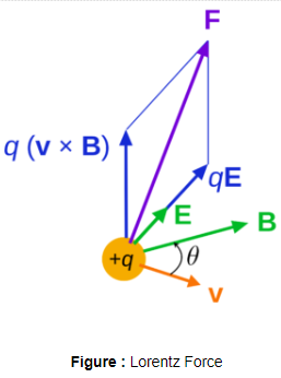
Ager koi charge q kisi magnetic field →B me velocity →v se move kare to magnetic force (→Fm) experience karta hai
→Fm=q(→v×→B)
Charge q total lorentz force F experience karta hai joki electric aur magnetic force ka addition hota hai.
So Lorentz force,
→F=→Fe+→Fm
→F=q(→E+→v×→B)
Magnetic force on a current-carrying conductor
Kisi current carrying conductor ke magnetic field me magnetic force experience hota hai. Yaha mainly teen chize hai - magnetic force, magnetic field and currect. In teeno me se kisi ki bhi direction find karne ke liye scientist ne kuchh rules diye jaise ki Fleming's left hand rule, Fleming's right hand rule and Thumb rule etc.Fleming's Left Hand Rule
Fleming left hand rule, magnetic field and current ke present me magnetic force ki direction find karne ke liye use kiya jata hai.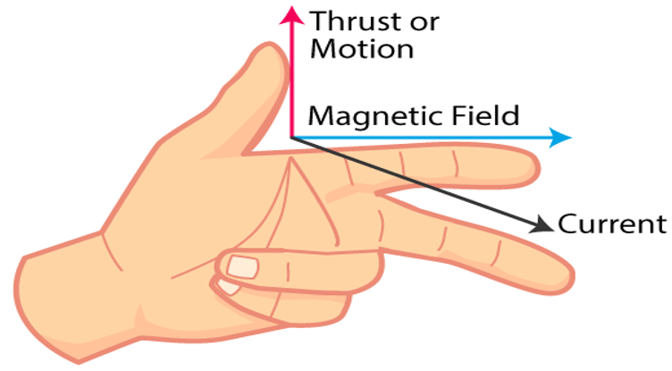
- According to this rule hume left hand lena hai jiske thumb, index finger aur middle finger ko ek dusre ke perpendicular failana hai. Aise situation me index finger hai magnetic field (→B), and middle finger hai current (→I) to thumb jo majboot hota hai wo force (→F) ki direction deta hai.
Fleming's Right Hand Rule
Fleming right hand rule, magnetic force and magnetic field ke present me induced current ki direction find karne ke liye use kiya jata hai.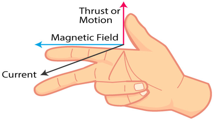
According to this rule hume right hand lena hai jiske thumb, index finger aur middle finger ko ek dusre ke perpendicular failana hai. Ager forefinger direction of the magnetic field represent karti hai, thumb direction of motion or applied force ko represent karta hai, to middle finger direction of the induced current ko represent krta hai.
Magnetic Fields Produced by Electrical Currents
Ager kisi conductor me electric current flow ho raha hai to is flowing current ke karan wire conductor ke aas-paas magnetic field produce hota hai, jiski direction find karne ke liye hum Right hand thumb rule use karte hai.Right hand Thumb rule
Jab kisi conductor me current flow ho rahi hai to iske liye magnetic field ki direction current ki direction ke perpendicular hoti hai. Let's say ki aapke right hand ka thumb current ki direction ko represent karta hai to aapke thumb ke perpendicular aapke fingers ko straight failane se ye magnetic field ki direction ko represent karte hai. Jaisa ki aap figure me dekh sakte ho ki fingers ko modne pr conductor ke jis side me ye fingers bahar ki taraf hote hai wo outword magnetic field (→Bout) aur jis side me fingers ander ki taraf hote hai wo inward magnetic field (→Bin) hota hai. Is tarah se kisi straight conductor ke surroungs me circuilar magnetic field lines hoti hai.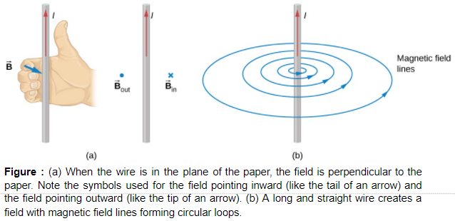
Force On Current Carrying Wire
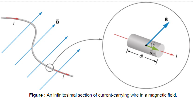
Ek current carrying wire lete hai jisme i current ja ry hai. Ab is wire ka chhota sa tukda dl lete hai is wire ka cross section area A hai. Conductor me current flow hone se electron drift karte hai jiski drift velocity hai vd. Chhote se element me current flow hone se force hum likh sakte hai.
F=q(ve∨d×→B)
dl element se gujar ke charge aya hai.
q=e−×n×A×dl
Isliye force ho jayega
F=neAdl(→vd×→B)
F=neAvddlBsinθ
F=i(→dl×→B)
OMR (One Minute Revision)
- * The concept of a field was specially stressed by Faraday and was incorporated by Maxwell in his unification of electricity and magnetism.
* Superposition simply means that if several magnets create magnetic fields, the fields at each point in space are some of the contributions of each magnet. This principle is also called "linearity".
* When the expression for the magnetic force is combined with that for the electric force, the combined expression is known as the Lorentz force.
* Magnetic force on current can be found by summing the magnetic force on each of the individual charges that make this current.
* For a wire exposed to a magnetic field,
F=IlBsinθ
describes the relationship between magnetic force (F), current (I), length of wire (l), magnetic field (B), and angle between field and wire (θ).
* The direction of the magnetic force can be determined using the right hand rule.
* The right hand rule states that, to find the direction of the magnetic force on a positive moving charge, the thumb of the right hand point in the direction of v, the fingers in the direction of B, and the force (F) is directed perpendicular to the right hand palm.
* The direction of the force F on a negative charge is in the opposite sense to that above (so pointed away from the back of your hand).
CONCEPT OF MAGNETIC FIELD
Magnetic field wo area hota hai jaha pr kisi magnets ki wajah se ek field bn jata hai, jiska effect is magnet ke aaspaas hota hai. Effect Kaise mahsus karenge? Maan lo ki kisi lohe ke tukde ko kisi magnet ke aaspaas le jane se ager ye tukda attract hota hai means isme force lagta hai to aap samjh jayenge ki ye magnetic field hai. The space around the magnet within which its influenced is called its magnetic field. Wo space jaha tak kisi magnet ki existence ya presence feel kiya ja sake use magnetic field kahte hai. Magnetic field ek vector quantity hai jiska symbol B aur SI unit tesla hai.
- The source of the magnetic field is moving charges. Jab hum pre existing field me koi charge le jate hai to usme magnetic force apply hone lagta hai.
Oersted experiment
Ek current carrying conductor ke pass magnetic compass rakhe, jaise hi current conductor se flow hua compass me deflection hua. Magnetic compass tabhi deflect hota hai jab uske aaspaas magnetic field present ho kyuki yahi compass pr force lagata hai aur deflection aata hai. Iska mtlb hai ager conductor me current flow karane ke baad hi magnetic deflection hua mtlb current ke flow se hi magnetic field conductor ke around create hua. Jab current flow karna band kr de to deflection zero ho jata hai. Iske alawa ager current ko opposite direction me flow karaye to magnetic compass me deflection dusre direction me ho jata hai.Magnetic compass me deflection dene wala koi aur nahi balki current hi hai. Jisko different diection me flow karne pr compass me deflection different direction me show karta hai kyuki current high magnetic field bana raha hai.

Conclusion - Oersted ke is experiment se hume conclusion ye mila ki current carrying conductor hi magnetic field banata hai ya produce karta hai.
- Current carrying conductor produces a magnetic field.
1. A current or a moving charge creates a magnetic field in the surrounding space (in addition to its electric field).
2. The magnetic field exerts a force on any other moving charge or current that is present in the field.
MAGNETIC FORCE
Jab kisi magnet ke magnetic field me iron ya magnetic material ko le jane se inme jo attraction or repultion force lgta hai yahi magnetic force hai.Sources and fields
Magnetic force ke source hai- magnet and moving charges. In magnetic force ke sources ke surrounding me jaha tak magnetic force ko feel kr sakte hai wo area in sources ka magnetic field hai. The concept of a field was specially stressed by Faraday and was incorporated by Maxwell in his unification of electricity and magnetism.Ager moving charges ke karan magnetic field create ho raha hai to is magnetic field me kisi particular point pr ye field ek ya ek se jyada moving charges ke karan ho sakta hai. Jab more charges ke karan us particular point pr field hai to ye field hr ek charges ke karan fields ko vectorially add karke find kiya jata hai jo principle of superposition kehlata hai. The field at a particular point can be due to one or more charges. If there are more charges the fields add vectorially. You have already learnt; this is called the principle of superposition.

Properties of magnetic field
* Magnetic field lines ek aisi imaginary lines hai jisme tangent dal de to ye magnetic field ki direction ko batati hai.* Magnetic field lines humesha closed loop banati hai.
* Magnetic field lines magnet ke bahar humesha north se south ki taraf jati hai aur magnet ke ander south se north jati hai.
* Magnetic field lines kabhi ek dusre ko intersect nahi karti kyuki ager cross ki to intersection point pe ye tangent ho jayegi jo possible nahi hai.
* Magnetic field lines ki density hume lines ki intensity define karti hai, jaha pr magnetic field lines pass-pass hai waha strong magnetic field aur jaha magnetic field lines dur-dur honge waha weak magnetic field hota hai.
Magnetic Field, Lorentz Force
Jab hum kevel Lorentz force ki baat karte hai to ye force electric aur magnetic dono force ke karan hota hai. Ager kisi aise region me charge particle move karta hai jaha electric aur magnetic dono field present ho waha ye charge particle jo total force experience karta hai wahi Lorentz force kehlata hai. The total force experienced by a charged particle moving in a region where both electric and magnetic fields are present, called Lorentz force.Electric field me koi charge q electric force (→Fe) experience karta hai.
→Fe=q→E

Ager koi charge q kisi magnetic field →B me velocity →v se move kare to magnetic force (→Fm) experience karta hai
→Fm=q(→v×→B)
Charge q total lorentz force F experience karta hai joki electric aur magnetic force ka addition hota hai.
So Lorentz force,
→F=→Fe+→Fm
→F=q(→E+→v×→B)
Magnetic force on a current-carrying conductor
Kisi current carrying conductor ke magnetic field me magnetic force experience hota hai. Yaha mainly teen chize hai - magnetic force, magnetic field and currect. In teeno me se kisi ki bhi direction find karne ke liye scientist ne kuchh rules diye jaise ki Fleming's left hand rule, Fleming's right hand rule and Thumb rule etc.Fleming's Left Hand Rule
Fleming left hand rule, magnetic field and current ke present me magnetic force ki direction find karne ke liye use kiya jata hai.
- According to this rule hume left hand lena hai jiske thumb, index finger aur middle finger ko ek dusre ke perpendicular failana hai. Aise situation me index finger hai magnetic field (→B), and middle finger hai current (→I) to thumb jo majboot hota hai wo force (→F) ki direction deta hai.
Fleming's Right Hand Rule
Fleming right hand rule, magnetic force and magnetic field ke present me induced current ki direction find karne ke liye use kiya jata hai.
According to this rule hume right hand lena hai jiske thumb, index finger aur middle finger ko ek dusre ke perpendicular failana hai. Ager forefinger direction of the magnetic field represent karti hai, thumb direction of motion or applied force ko represent karta hai, to middle finger direction of the induced current ko represent krta hai.
Magnetic Fields Produced by Electrical Currents
Ager kisi conductor me electric current flow ho raha hai to is flowing current ke karan wire conductor ke aas-paas magnetic field produce hota hai, jiski direction find karne ke liye hum Right hand thumb rule use karte hai.Right hand Thumb rule
Jab kisi conductor me current flow ho rahi hai to iske liye magnetic field ki direction current ki direction ke perpendicular hoti hai. Let's say ki aapke right hand ka thumb current ki direction ko represent karta hai to aapke thumb ke perpendicular aapke fingers ko straight failane se ye magnetic field ki direction ko represent karte hai. Jaisa ki aap figure me dekh sakte ho ki fingers ko modne pr conductor ke jis side me ye fingers bahar ki taraf hote hai wo outword magnetic field (→Bout) aur jis side me fingers ander ki taraf hote hai wo inward magnetic field (→Bin) hota hai. Is tarah se kisi straight conductor ke surroungs me circuilar magnetic field lines hoti hai.
Force On Current Carrying Wire

Ek current carrying wire lete hai jisme i current ja ry hai. Ab is wire ka chhota sa tukda dl lete hai is wire ka cross section area A hai. Conductor me current flow hone se electron drift karte hai jiski drift velocity hai vd. Chhote se element me current flow hone se force hum likh sakte hai.
F=q(ve∨d×→B)
dl element se gujar ke charge aya hai.
q=e−×n×A×dl
Isliye force ho jayega
F=neAdl(→vd×→B)
F=neAvddlBsinθ
F=i(→dl×→B)
OMR (One Minute Revision)
- * The concept of a field was specially stressed by Faraday and was incorporated by Maxwell in his unification of electricity and magnetism.
* Superposition simply means that if several magnets create magnetic fields, the fields at each point in space are some of the contributions of each magnet. This principle is also called "linearity".
* When the expression for the magnetic force is combined with that for the electric force, the combined expression is known as the Lorentz force.
* Magnetic force on current can be found by summing the magnetic force on each of the individual charges that make this current.
* For a wire exposed to a magnetic field,
F=IlBsinθ
describes the relationship between magnetic force (F), current (I), length of wire (l), magnetic field (B), and angle between field and wire (θ).
* The direction of the magnetic force can be determined using the right hand rule.
* The right hand rule states that, to find the direction of the magnetic force on a positive moving charge, the thumb of the right hand point in the direction of v, the fingers in the direction of B, and the force (F) is directed perpendicular to the right hand palm.
* The direction of the force F on a negative charge is in the opposite sense to that above (so pointed away from the back of your hand).
POINT 1
Magnetic Force :
Magnetic Force can be defined as the attractive or repulsive force that is exerted between the poles of a magnet and electrically charged moving particles. Hence, it is a consequence of the electromagnetic forces.
Principle of Superposition for magnetism :
The field at a particular point can be due to one or more charges. If there are more charges the fields add vectorially. You have already learnt; this is called the principle of superposition.
Lorentz Force :
The total force experienced by a charged particle moving in a region where both electric and magnetic fields are present , called lorentz force.
→F=q(→E+→v×→B)
Fleming Left Hand Rule :
Hold out your left hand with the forefinger, second finger and thumb perpendicular to each other. If the forefinger represents the direction of the field and the second finger represents that of the current, then the thumb gives the direction of the force.
Fleming Right Hand Rule :
Hold the right-hand forefinger, middle finger and the thumb at right angles to each other. If the forefinger represents the direction of the magnetic field, the thumb points in the direction of motion or applied force, then the middle finger points in the direction of the induced current.
MOTION IN A MAGNETIC FIELD
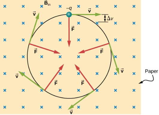
Uniform magnetic field me charge particle ager 90∘ angle se enter karte hai to magnetic field aur velocity ke bich 90∘ angle banta hai. Ye charge particle circular motion me move karta hai jo magnetic lorentz force deta hai. Velocity aur force perpendicular direction me hote hai; isliye force, velocity ki direction ko apni taraf deviate karne ki kosis karta hai jo hr point pr hota hai. Charge particle ke motion me velocity tangential hai aur hr point pr magnetic field ander ki taraf hai. Toward the centre yaha force lg raha hai. Yahi karan hai ki charge particle circular motion me ghumta hai jo r radius banata hai aur ek circle ghumne ke liye time T lagta hai. Iski frequency fc hoti hai, cyclotron frequency iska nam hai but ye cyclotron frequency nahi hai.
r=mvqB
T=2πrv=2πvmvqB=2πmqB
T=2πmqB
Time period T, velocity v pe depend hi nahi karta.
Angular velocuty
ω=2πT=qBm
- Jaha pr bhi force velocity ke perpendiular ho jaye waha pr motion circular motion hota hai.
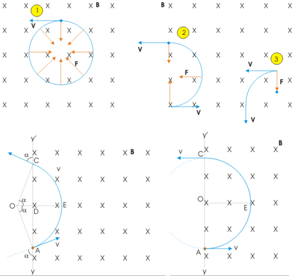
When The Charge Particle Is Moving At An Angle To The Field
Jab charge particle 90∘ angle pr magnetic field me enter na kr kisi angle α se enter kare to charge particle circular motion nahi karega (shown in above figure). Ager x-axis se α angle pr charge particle ki entry hoti hai to iske do component ho jate hai Vpara and Vperp (shown in below figure). Vpara charge particle ko aage le jata hai aur Vperp charge particle ko ghumata hai. To ab charge particle ghum bhi raha hai aur aage badh bhi raha hai ye spring ki tarah motion hota hai jise helical motion kahte hai.r=mVperpqB
r wo radius hai jisse moving charge magnetic field me ghum raha hai.
Time peroid
T=2πmqB
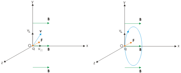
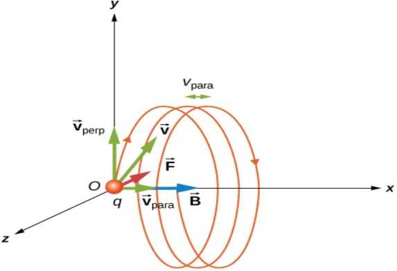
Pitch - Ek chakker lagane ke baad dusre round tk phuchne ke liye kitna aage khisak gaya use pitch kahte hai. Distance covered by the center of the circle in one rotation in the direction of the magnetic field.
MOTION IN COMBINED ELECTRIC AND MAGNETIC FIELDS
Velocity selector
Jab electric field aur magnetic field dono lagte hai tab jo force lagta hai use lorentz force kahte hain.→F=q(→E+→v×→B)
Case 1 - When →v,→E and →B all the three are collinear
Jab kisi area me electric aur magnetic field present hai to charge particle pr dono hi field apna apna force lagayenge. Charge particle ki velocity is case me magnetic field ke direction me hogi isliye →v aur →B ke bich angle zero hoga jisse charge particle pr magnetic force zero ho jayega aur kevel electric force lagega.
→F=q→E
Is charge particle ka path hoga straight line.
→a=→Fm=q→Em
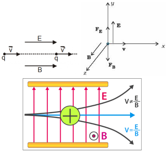
Case 2 - When →v,→E and →B all are perpendicular to each other
Is case me net force zero hoga kyuki electric force aur magnetic force ek dusre ke equal and opposite ho jayenge isliye electric field aur magnetic field ka ratio charge particle ke velocity ke equal ho jayega.
Fe=FB
qE=qvB
v=EB
Is case me charge ki velocity me koi deviation nahi hota, jis velocity se charge particle field me enter karta hai usi velocity se receiving end pr hume milta hai. Electric field bhi hai magnetic field bhi hai fr bhi charge particle ka velocity deviate nahi ho raha ise hi velocity selector kahte hai.
Cyclotron
Ye ek tarah ka equipment hota hai jo charge particles ya ions ko high energy (velocity) me accelerate karta hai. Cyclotron ke use se hum electric aur magnetic field create krte hai, jisse charge particles ki enegy ko increase kiya jata hai.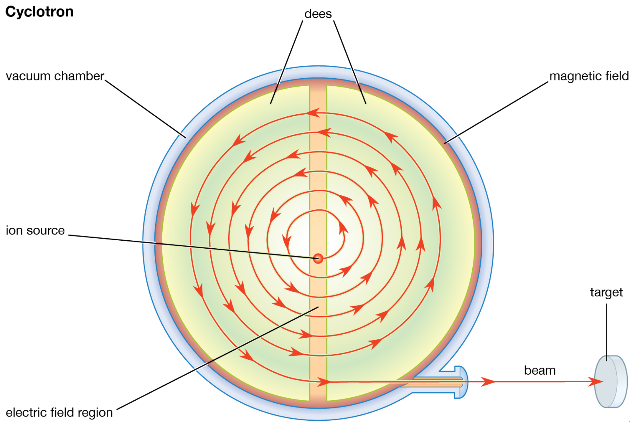
P is a point jise hum charge particle ka source mante hai, jo apne axis me circular motion me move krte hai. D1 aur D2 magnetic disc hai jo ek dusre ke perpendicular hota hai. Jab disc ko ac voltage supply dete hai jo disc me P point pr present charged particle ke movement ke speed ko increase krta hai jisse charged particle circular motion me move karte hue exit part se disc se bahar chala jata hai. Charged particle jis frequency se move karta hai use cyclotron frequency kahte hai jise fc se show karte hai.
Cyclotron frequency
fc=qB2πm
Working Principle of Cyclotron
D1 aur D2 do hollow metallic disc hote hai jo ki semicircular shape me hai. Disc do type ka function perform karta hai.Let's assume, do semicircular disc ke beech, air gap me ek source se positive charge inject krte hai. D1, D2 do electrode hai, jo ki high frequency alternating voltage se attached hota hai. AC voltage ke sinusoidal voltage ke wajah se D1 electrode negative charge hota hai, jisse positive charge particles ko apne taraf attract karta hai. At same time magnetic field ke wajah se charge particles me centripetal force develop hota hai jo charge particles ko circular path me move krne me help karta hai. By the time uska radius increase hota jata hai. Jaise hi charge particles circular path complete krke gap me enter karta hai D2 me negative charge create hota hai jisse charge particles D2 ke taraf attract hota hai, usi samay magnetic field ki wajah se yaha bhi centripetal force create hota hai aur charge particles ko circular path me move krwata hai, Jab jab charge particles gap se nikal kr dusre electrode me jata hai uske velocity bhut increase ho jata hai aur circular motion ka radius badhta chala jata hai, phir ek time ke baad wah electrode ke periphery me pahuch kr exit way se bahar target pr inject hota hai.
Application of Cyclotron
Limitation of Cyclotron
OMR (One Minute Revision)
- * Magnetic fields exert forces on charged particles in motion.
* The direction of the magnetic force F is perpendicular to the plane formed by v and B as determined by the right hand rule.
* The SI unit for magnitude of the magnetic field strength is called the tesla (T), which is equivalent to one Newton per ampere-meter. Sometimes the smaller unit gauss (10−4 T) is used instead.
* When considering the motion of a charged particle in a magnetic field, the relevant vectors are the magnetic field B, the velocity of the particle v, and the magnetic force exerted on the particle F. These vectors are all perpendicular to each other.
MOTION IN A MAGNETIC FIELD

Uniform magnetic field me charge particle ager 90∘ angle se enter karte hai to magnetic field aur velocity ke bich 90∘ angle banta hai. Ye charge particle circular motion me move karta hai jo magnetic lorentz force deta hai. Velocity aur force perpendicular direction me hote hai; isliye force, velocity ki direction ko apni taraf deviate karne ki kosis karta hai jo hr point pr hota hai. Charge particle ke motion me velocity tangential hai aur hr point pr magnetic field ander ki taraf hai. Toward the centre yaha force lg raha hai. Yahi karan hai ki charge particle circular motion me ghumta hai jo r radius banata hai aur ek circle ghumne ke liye time T lagta hai. Iski frequency fc hoti hai, cyclotron frequency iska nam hai but ye cyclotron frequency nahi hai.
r=mvqB
T=2πrv=2πvmvqB=2πmqB
T=2πmqB
Time period T, velocity v pe depend hi nahi karta.
Angular velocuty
ω=2πT=qBm
- Jaha pr bhi force velocity ke perpendiular ho jaye waha pr motion circular motion hota hai.

When The Charge Particle Is Moving At An Angle To The Field
Jab charge particle 90∘ angle pr magnetic field me enter na kr kisi angle α se enter kare to charge particle circular motion nahi karega (shown in above figure). Ager x-axis se α angle pr charge particle ki entry hoti hai to iske do component ho jate hai Vpara and Vperp (shown in below figure). Vpara charge particle ko aage le jata hai aur Vperp charge particle ko ghumata hai. To ab charge particle ghum bhi raha hai aur aage badh bhi raha hai ye spring ki tarah motion hota hai jise helical motion kahte hai.r=mVperpqB
r wo radius hai jisse moving charge magnetic field me ghum raha hai.
Time peroid
T=2πmqB


Pitch - Ek chakker lagane ke baad dusre round tk phuchne ke liye kitna aage khisak gaya use pitch kahte hai. Distance covered by the center of the circle in one rotation in the direction of the magnetic field.
MOTION IN COMBINED ELECTRIC AND MAGNETIC FIELDS
Velocity selector
Jab electric field aur magnetic field dono lagte hai tab jo force lagta hai use lorentz force kahte hain.→F=q(→E+→v×→B)
Case 1 - When →v,→E and →B all the three are collinear
Jab kisi area me electric aur magnetic field present hai to charge particle pr dono hi field apna apna force lagayenge. Charge particle ki velocity is case me magnetic field ke direction me hogi isliye →v aur →B ke bich angle zero hoga jisse charge particle pr magnetic force zero ho jayega aur kevel electric force lagega.
→F=q→E
Is charge particle ka path hoga straight line.
→a=→Fm=q→Em

Case 2 - When →v,→E and →B all are perpendicular to each other
Is case me net force zero hoga kyuki electric force aur magnetic force ek dusre ke equal and opposite ho jayenge isliye electric field aur magnetic field ka ratio charge particle ke velocity ke equal ho jayega.
Fe=FB
qE=qvB
v=EB
Is case me charge ki velocity me koi deviation nahi hota, jis velocity se charge particle field me enter karta hai usi velocity se receiving end pr hume milta hai. Electric field bhi hai magnetic field bhi hai fr bhi charge particle ka velocity deviate nahi ho raha ise hi velocity selector kahte hai.
Cyclotron
Ye ek tarah ka equipment hota hai jo charge particles ya ions ko high energy (velocity) me accelerate karta hai. Cyclotron ke use se hum electric aur magnetic field create krte hai, jisse charge particles ki enegy ko increase kiya jata hai.
P is a point jise hum charge particle ka source mante hai, jo apne axis me circular motion me move krte hai. D1 aur D2 magnetic disc hai jo ek dusre ke perpendicular hota hai. Jab disc ko ac voltage supply dete hai jo disc me P point pr present charged particle ke movement ke speed ko increase krta hai jisse charged particle circular motion me move karte hue exit part se disc se bahar chala jata hai. Charged particle jis frequency se move karta hai use cyclotron frequency kahte hai jise fc se show karte hai.
Cyclotron frequency
fc=qB2πm
Working Principle of Cyclotron
D1 aur D2 do hollow metallic disc hote hai jo ki semicircular shape me hai. Disc do type ka function perform karta hai.Let's assume, do semicircular disc ke beech, air gap me ek source se positive charge inject krte hai. D1, D2 do electrode hai, jo ki high frequency alternating voltage se attached hota hai. AC voltage ke sinusoidal voltage ke wajah se D1 electrode negative charge hota hai, jisse positive charge particles ko apne taraf attract karta hai. At same time magnetic field ke wajah se charge particles me centripetal force develop hota hai jo charge particles ko circular path me move krne me help karta hai. By the time uska radius increase hota jata hai. Jaise hi charge particles circular path complete krke gap me enter karta hai D2 me negative charge create hota hai jisse charge particles D2 ke taraf attract hota hai, usi samay magnetic field ki wajah se yaha bhi centripetal force create hota hai aur charge particles ko circular path me move krwata hai, Jab jab charge particles gap se nikal kr dusre electrode me jata hai uske velocity bhut increase ho jata hai aur circular motion ka radius badhta chala jata hai, phir ek time ke baad wah electrode ke periphery me pahuch kr exit way se bahar target pr inject hota hai.
Application of Cyclotron
Limitation of Cyclotron
OMR (One Minute Revision)
- * Magnetic fields exert forces on charged particles in motion.
* The direction of the magnetic force F is perpendicular to the plane formed by v and B as determined by the right hand rule.
* The SI unit for magnitude of the magnetic field strength is called the tesla (T), which is equivalent to one Newton per ampere-meter. Sometimes the smaller unit gauss (10−4 T) is used instead.
* When considering the motion of a charged particle in a magnetic field, the relevant vectors are the magnetic field B, the velocity of the particle v, and the magnetic force exerted on the particle F. These vectors are all perpendicular to each other.
POINT 2
Circular Motion of Charged Particle in Magnetic Field :
A negatively charged particle moves in the plane of the page in a region where the magnetic field is perpendicular into the page (represented by the small circles with x’s—like the tails of arrows). The magnetic force is perpendicular to the velocity, and so velocity changes in direction but not magnitude. Uniform circular motion results.
Helical Motion :
The motion that is produced when one component of the velocity is constant in magnitude and direction (i.e., straight-line motion) while the other component is constant in speed but uniformly varies in direction (i.e., circular motion). It is the superposition of straight-line and circular motion.
Pitch :
Distance covered by the center of the circle in one rotation in the direction of the magnetic field.
Velocity Selector :
A velocity selector is a region of space occupied by a uniform electric and magnetic field mutually perpendicular. When a beam of charged particles travels perpendicular through the selector, only those with a velocity equal to the ratio between the electric and the magnetic field can pass undeflected.
EXAMPLE 1
A straight wire of mass 200 g and length 1.5 m carries a current of 2 A. It is suspended in mid-air by a uniform horizontal magnetic field B (Fig.). What is the magnitude of the magnetic field?
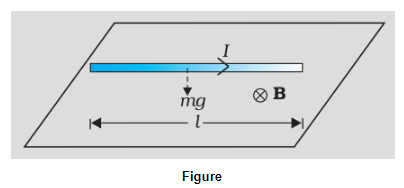
We find an upward force F, of magnitude IlB. For mid-air suspension, this must be balanced by the force due to gravity:
mg=IlB
B=mgIl
=0.2×9.82×1.5=0.65T
Note that it would have been sufficient to specify m/l, the mass per unit length of the wire. The earth’s magnetic field is approximately 4×10⁻⁵T and we have ignored it.
EXAMPLE 1
Verify that the cyclotron frequency ω=eB/m has the correct dimensions of [T]−1.
For a charge particle moving perpendicular to the magnetic field, the magnetic Lorentz forces provides necessary centripetal force for revolution.
mv2R=qvB
On simpilfying the terms, we have
qBm=vR=ω
Finding the dimensional formula of angular frequency
∴[ω]=[qBm]=[vR]=[T]−1.
EXAMPLE 2
If the magnetic field is parallel to the positive y-axis and the charged particle is moving along the positive x-axis (Fig.), which way would the Lorentz force be for (a) an electron (negative charge), (b) a proton (positive charge). ?
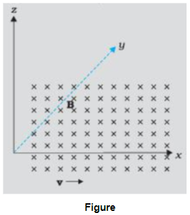
The velocity v of particles is along the x-axis, while B, the magnetic field is along the y-axis, so v×B is along the z-axis (screw rule or right-hand thumb rule). So,
(a) for electrons it will be along –z axis.
(b) for a positive charge (proton) the force is along the +z axis.
EXAMPLE 2
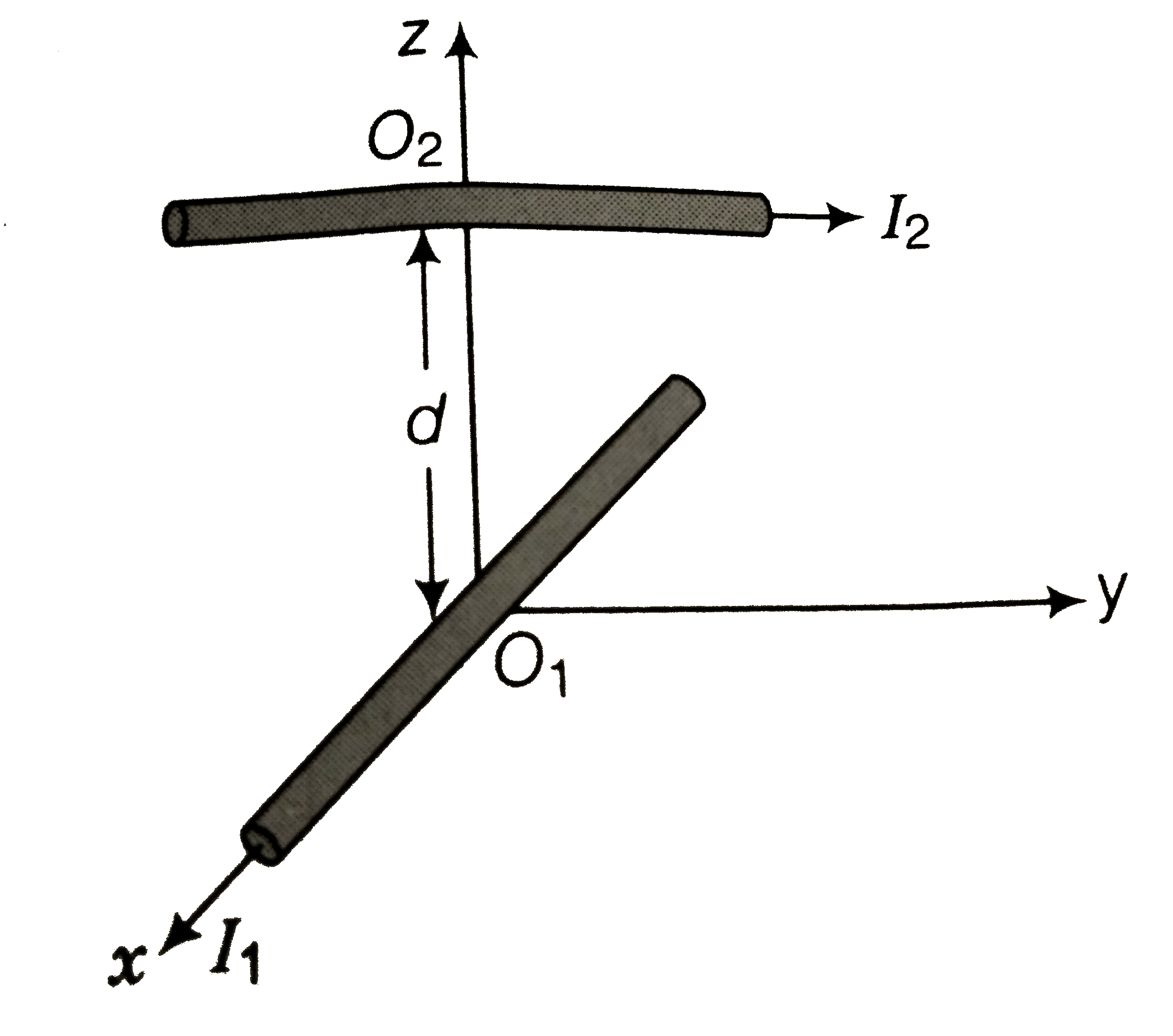
Two long wires carrying current I1andI2 are arranged as shown in figure the one carrying current I1 is along is the x-axis. The other carrying current I2 is along a line parallel to the y-axis given by x=0 and z=d. Find the force exerted at O2 because of the wire along the x-axis.
In Biot-Savart law, magnetic field B is parallel to idl×r and idl have its direction along the direction of flow of current.
Here. For the direction of magnetic field, At O2 due to wire carrying I1 carrying is
B∣∣parallel ×r or ˆi׈k but ˆi׈k=−ˆj
So, the direction at O2 is along Y-direction
The direction of magnetic force exerted at O2 because of the wire along the x-axis
F=Il×B=ˆj×(−ˆj)=0
So, the magnetic field due to l1 is along the y-axis the second wire is along the y-axis and hence, the force is zero.
EXAMPLE 3
What is the radius of the path of an electron (mass 9×10⁻³¹kg and charge 1.6×10⁻¹⁹C) moving at a speed of 3×10⁷m/s in a magnetic field of 6×10⁻⁴T perpendicular to it? What is its frequency? Calculate its energy in keV. ( 1eV=1.6×10⁻¹⁹J)
We have r=mvqB
=9×10–31kg×3×107ms–11.6×10–19C×6×10–4T
=26×10–2m
=26cm
ν=ν2πr
=2×10⁶s–1
=2×10⁶Hz
=2MHz
E = (½ )mv^2
=(½)9×10–31kg×9×1014m2/s2
=40.5×10⁻¹⁷J
≈4×10–16J=2.5keV
EXAMPLE 3
A current carrying loop consists of 3 identical quarter circles of radius R, lying in the positive quadrants of the x-y, y-z and z-x planes with their centres at the origin, joined together. Find the direction and magnitude to →B at the origin.
For the current carrying loop quarter circles of radius R, lying in the positive quadrants of the x-y plane
B1=μ04πI(π/2)Rˆk=μ04I2Rˆk
For the current carrying loop quarter circles of radius R, lying int he positive quadrants of the y-z plane
B2=μ04I2Rˆi
For The current carrying loop quarter circles of radius R, lying in the positive quadrants of the z-x plane
B3=μ04I2Rˆi
Current carrying loop consists of 3 identical quarter circles of radius R, lying in the positive quadrants of the x-y, y-y and z-z planes with their centres at the origin, joined together is equal to the vector sum of magnetic field due to each quarter and given by
B=14π(ˆi+ˆj+ˆk)μ0I2R
EXAMPLE 4
A cyclotron’s oscillator frequency is 10 MHz. What should be the operating magnetic field for accelerating protons? If the radius of its ‘dees’ is 60 cm, what is the kinetic energy (in MeV) of the proton beam produced by the accelerator. (e=1.60×10⁻¹⁹C, mp=1.67×10⁻²⁷kg, 1MeV=1.6×10⁻¹³J).
The oscillator frequency should be the same as proton’s cyclotron frequency.
We have B=2πmνq
=6.3×1.67×10–27×1071.6×10–19
=0.66T
Final velocity of protons is
ν=r×2πν
=0.6m×6.3×107
=3.78×10⁷m/s
E=½mv2
=1.67×10–27×14.3×10142×1.6×10–13
=7MeV
EXAMPLE 5
Verify that the cyclotron frequency ω=eB/m has the correct dimensions of [T]−1.
For a charge particle moving perpendiuclar to the magnetic field, the magnetic Lorentz forces provides necessary centripetal force for revolution.
mv2R=qvB
On simpilfyting the terms, we have
qBm=vR=ω
Finding the dimensional formula of angular frequency
∴[ω]=[qBm]=[vR]=[T]−1.
EXAMPLE 6
The magnetic force depends on v which depends on the inertial frame of reference. Does then the magnetic force differ from inertial frame to frame? Is it reasonable that the net acceleration has a different value in different frames of reference?
Yes, the magnetic force differ from inertial frame to frame. The magnetic force is frame dependent.
The net acceleration which comes into existing out of this is however, frame independent (non-relativistic physics) for inertial frames.
MAGNETIC FIELD DUE TO A CURRENT ELEMENT, BIOT-SAVART LAW
Tufani law - Jo kahani aapne pehle chapter me coulomb’s law se sikhi thi ki point charge kitna force lagayega. Isi tarah magnetism me biot savart's law hota hai. Biot Savart's law ye btata hai ki ek current element se kitna magnetic field banta hai. Coulomb's law me baat ki gai thi point charge ki aur yaha pr baat karenge current element ki.
Abhi humne samjha ki magnetic field current se banta hai lekin kitna banta hai? Jo current limit hai Idl ye hai current element. Ye chhota sa current hai aur dl bht hi small length of conductor hai jisko point tukda samjh lijiye. Jab current ko wire me flow karayenge tb magnetic field produce hogi. Current flow hone ke baad wire ka dl element liya hai jiska direction current I ke hi direction me lete hai. Is dl se Idl hi current element hai. Jaise ki coulomb’s law point charge ke liye tha usi tarah se Idl current element kitna magnetic field banayega yahi biot savart’s law ne diya ye magnetism ke liye basic law hai jo bht important hai.
We assume that this field is made up of contributions from different segments of the conductor, called current elements. A current element is denoted by Idl, and has the same direction as that of current I.
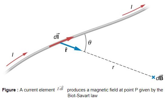
Current ke flow hone se koi point P lete hai jaha pr magnetic field d→B ban raha hai wo is current element ke chhote chhote tukde jo magnetic field bana rahe hai un sbka sum hai. is point magnetic field inward hai isliye ise humne × se show kiya hai.
dl and Idl ka direction same hoga. Chhota sa current element chhota sa magnetic field banayegi. Ye chhota sa magnetic field kitna banega yahi Biot savart’s law se milti hai.
dB=μ04π.Idlsinθr2
sinθ means current element se point P kitna angle (θ) bna raha hai. Wire se point P ki distance r hai jiski direction jis point pr magnetic field nikalna hai uske along hogi. So, magnetic field
d→B=μ0I4π.→dl×→r|→r|3
μ0=4π×10−7TA−1m
Magnetic field vector quantity hai.
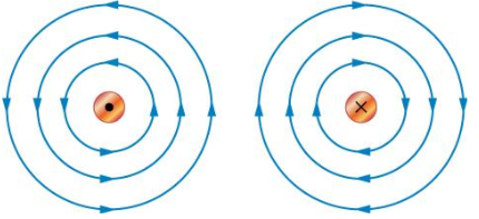
- Direction of Idl kis taraf hota hai? dl×r ka mtlb vector law se vector product nikalte the cross product right hand palm rule se palm ko aise set karna jaise ki palm r ki taraf mude to dl aur r ki direction hatheli mud jati hai. Kyuki ab thumb ander taraf hai to yahi direction of magnetic field ho jata hai. Magnetic field ki direction ander ki tarf ho to use × se show karte hai.
Magnitude of magnetic field is
dB=μ0i4π.dl.rsinθr3
Magnetic field ki unit Wb/m2 ya Tesla hoti hai.
- × ka mtlb hai magnetic field ki direction inside the plane hogi aur ⋅ ka mtlb hai magnetic field ki direction outside the plane hogi. (shown in below figure)
FIELD DUE TO A STRAIGHT CURRENT WIRE
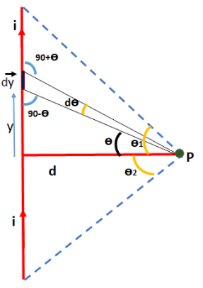
Ek straight wire hai aur is wire se perpendicular d duri pr magnetic field nikalna hai. Ise hum ampere circuital law se bhi proof karenge but usse pehle hum yaha pr biot savart law ka use karke proof karte hai. d duri pr jis point pe hume magnetic field nikalna hai us point se straight conductor ka 1st end point θ1 angle pr aur 2nd end θ2 angle pr lete hai. θ1 clockwise direction me upper end se angle bana raha hai. Aur θ2 anticlockwise direction me lower end se angle banata hai. Biot savart’s law se humne samjha ki kisi current element ki wajah hum magnetic field likh sakte hai chahe long straight wire ho ya koi loop.
d→B=μ04π→dl×→r|→r|3
dB yaha pr biot savart ke according element dy ke liye r duri pr magnetic field hai r vector ka head waha pr hoga jis point pr hume magnetic field nikalna hai. Element dy point se dthη angle bna raha hai .
dB=μ0i4π.dy.rsin(90+θ)r3
dB=μ0i4π.dy.cosθr2
Ye chhote se element ka magnetic field hai. Small element ko hum kahi bhi le sakte hai jiske liye variables hai θ aur r. Do variables ke sath integration karke whole wire ke liye magnetic field nikalna bht complex hoga isliye do variables ko hata ke single variable lane ke liye hum lete hai
tanθ=yd
y=dtanθ
dydθ=dsec2θ
dy=dsec2θdθ
cosθ=dr
r=dsecθ
ye dy aur r ki value ko hum magnetic field ke eq. mein put karte hai
dB=μ0i4π.(dsec2θdθ).cosθ(dsecθ)2
∫dB=∫θ1−θ2μ0i4πd.cosθdθ
B=μ0i4πd∫θ1−θ2cosθdθ
B=μ0i4πd[sinθ]θ1−θ2
B=μ0i4πd[sinθ1−sin(−θ2)]
B=μ0i4πd[sinθ1+sinθ2]
When the point P is on the perpendicular bisector
Is case me θ1 aur θ2 equal honge isliye B ke liye eq. ho jayegaB=μ0i4πd[sinθ+sinθ]
B=μ0i4πd2sinθ
B=μ0i2πdsinθ
Infinitely long wire
Ager wire infinitely long wire hui to d duri pe kisi point pr magnetic fieldB=μ0i4πd[sin90∘+sin90∘]
B=μ0i4πd[1+1]
B=μ0i4πd[2]
B=μ0i2πd
When the point lies along the length of wire (but not on it)
Koi wire jisme current ja ry ho I, ab is wire ke along point P pr magnetic field zero hoga.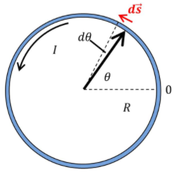
MAGNETIC FIELD ON THE AXIS OF A CIRCULAR CURRENT LOOP
Koi loop hai jiske centre se hume magnetic field nikalna hai. Sbse phle hum ek chhota sa element top most point me le lete hai jisme current ki direction figure me show ki gai hai.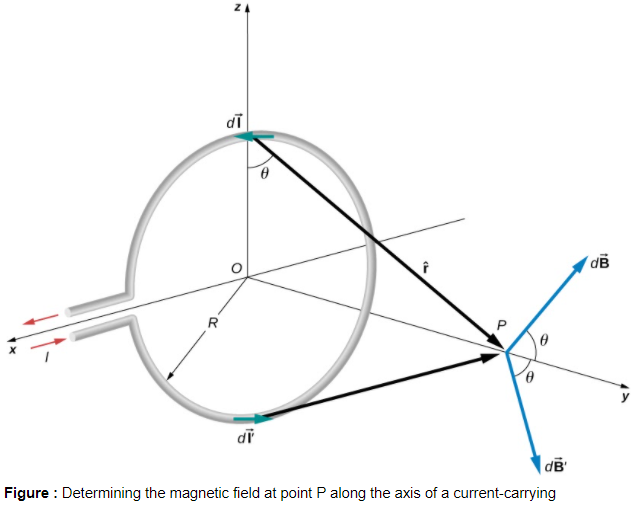
Ab ager is current element ke karan point P pr joki r duri me hume magnetic field nikalna ho to
dl aur r ke bich ka angle sinθ hai jisme θ=90∘ hai. Vector aur magnetic field ki direction hum thik usi tarah nikalenge jaise humne biot savart’s law ke liye nikali thi right hand palm rule (thappad rule) se vector ki direction point P ke along aur magnetic field B ki direction vector r ke direction ke perpendicular hogi jaise ki aap figure me dekh sakte hai.
dB=μ0I4πdlrsinθr3
because θ=90∘ and sinθ=1
So,
dB=μ0.I4πdlr2
jaise element uper hai vaisa hi ek element lower me (dl’) bhi hai to is element ke liye magnetic field
dB’=μ0.I4πdlr2
dl’ element ke liye current ki direction ander ki taraf hai isliye magnetic field dB’ ki direction niche ki tarah figure me dikhaya anusar hogi. Magnetic field dl aur r dono ke perpendicular hoga. Isliye dB aur dB’ ke components lenge kyon ki direction me magnetic field ka component dBcosθ hoga. Pure circular current loop ke liye magnetic field nikalne ke liye hum small element ke magnetic field ka integration kr denge.
⇒∫dBcosθ=μ0.I4πdlcosθR2+x2
where r=√R2+x2 and OP=x
⇒∫dBcosθ=μ0.I4π(R2+x2)R√R2+x2dl
where cosθ=R√R2+x2 hai.
So, B=∫μ0.IR4π(R2+x2)32dl
B=μ0.IR4π(R2+x2)32∫dl
B=μ0.IR4π(R2+x2)322πR
B=μ0.IR22(R2+x2)32
Yahi circular loop se point P pr magnetic field B hai. Ager hume is circular loop ke center pr magnetic field nikalna ho to OP=x=0 ho jayega jisse magnetic field
B=μ0.IR22(R2+02)32
B=μ0IR22R3
B=μ0I2R
Yahi circular loop ke center pr magnetic field hai. x=0 ke liye magnetic field ki value maximum hogi. Niche figure me aap circular loop ke liye magnetic field lines and graph dekh sakte hai.
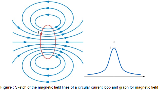
Field at the Centre of a Current Arc
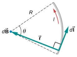
B=μ0i4πRθ
Field at the Centre of a Current Semicircle

B=μ0I4πRπ
B=μ0I4R
where θ=π because for semicircle angle θ=180∘
Field at the Centre of a Current Circle
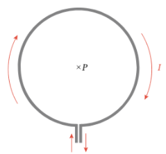
B=μ0I4πR2π
where θ=2π because for circle angle θ=360∘
AMPERE’S CIRCUITAL LAW
Jaise aapne chapter 1 me phle aapne coulomb’s law padha fr gauss law padha. Coulomb's law se force ke karan electric field and flux jo create hota hai use gauss law bade aasani se easily find kr deta hai but uske liye condition thi ki symmetric formation honi chaiye isi tarah yaha magnetism me biot savart's law jo magnetic field nikalta hai usse bade hi easy way me ampere circuital law find kr deta hai. Jo kam gauss law ne coulomb’s law ke liye electrostatics me kiya tha more or less wahi kaam ampere circuital law kr raha hai yaha pr biot savart’s law ke liye.Ampere’s circuital law states that the line integral of the magnetic field →B around any closed path is equal to μ0 (permeability constant) times the total current I passing through closed path.
∮→B.→dl=μoI
Net current inside the closed loop.
Kisi unit area se gujarne wali magnetic field lines hai →B.→dl
dl line vector hai jisko close karte hai to closed loop milta hai. Closed loop ke liye →B.→dl barabar hoga μ0 aur loop me jitni current hai uske.
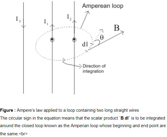
Uper diye gaye figure me aap dekh sakte hai jaha humne ek lamba current carrying conductor ke around ager magnetic field nikalna hai to hume ek closed circular path lena hota hai. Ab ye closed circular path conductor se r radius pr hai. Ab conductor ke around magnetic field nikalne ke liye line integral dl lenge means circular path ka chhota chhota hissa jisse milkr circular path bana hai. Closed path me line integral ke liye magnetic field B ki value path ke ander flow hone wale net current ke μ0 times hota hai. Yahi ampere’s circuital law hai. →B.→dl ke liye direction kisi bhi line integral ke along →B.→dl jaha positive aara hai us direction ki current ko hum positive lelenge. →B.→dl same direction me honge to current positive aur ager →B.→dl opposite direction me honge to current ko lenge negative.
The circular sign in the equation means that the scalar product B.dl is to be integrated around the closed loop known as the Amperian loop whose beginning and end point are the same.
Yaha pr dl humne anticlock wise maana hai kyuki current jo uper ja ry hai uske karan magnetic field bhi tangential hai aur chhota sa dl bhi tangential hai to ∮B.dlcos0=μ0Iin
yaha pr Iin mtlb jo loop ke ander current aary hai. Sare chhote chhote elements ko jodne se circle ka circumference (2πr) ban jayega.
B∮.→dl=μ0Iin
B(2πr)=μ0Iin
B=μ0Iin2πr
Ager current ki direction negative ho to magnetic field bhi negative ho jayega.
Ampere’s law to a infinite straight conductor
Magnetic field for current carrying conductorB=μ0I2πr
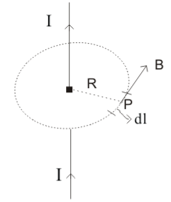
B is the magnetic field due to current carrying conductor at point P.
Maana ki koi infinite current carrying conductor hai jiske paas P point pr hume magnetic field nikalni hai to ek circular loop bana lete hai jo conductor se r radius pr hai. According to Ampere’s law
∮→B.→dl=μoI
Point P pr right hand thumb rule se tangentially magnetic field B ka direction aur dl ka direction bhi P point se tangential hi hoga isliye B aur dl ke bich circular loop ke hr point pr angle zero hoga.
∮B.dlcosθ=μoI
∮B.dlcos0∘=μoI
B∮dl=μoI
B×2πR=μ0×I
B=μ0I2πR
- Magnetic field line humesha close loop me exist karti hai isliye net flux through a closed surface zero hota hai. Is tarah se gauss law magnetism me hamesha zero hota hai.
Hollow Current Carrying Infinitely Long Cylinder : (I is uniformly distributed on the whole circumference)
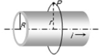
Kisi hollow cylinder ke sirf surface pr current flow hogi. Hume is cylinder ke karan magnetic field nikalna hai. Cylinder ke axis ke center se r duri pe magnetic field find out karna hai. r duri me ek loop lenge jise bolenge amperian loop aur ise anticlockwise lenge. Amperian loop ke ander total current i hai. According to ampere’s law
∮→B.→dl=μoi
∮B.dlcosθ=μoi
∮B.dlcos0∘=μoi
B∮dl=μoi
B×2πr=μ0×i
B=μ0i2πr
Ager cylinder ke ander magnetic field nikalna chahe to

Magnetic field ke ander center se r duri pe magnetic field nikalna chahe to isme se gujarta hua amperian loop bana lenge. Sari current to surface se hoker ja ry hai isiliye hollow cylinder ke ander magnetic field zero hota hai.
∮→B.→dl=μoi
because i=0 so, ∮→B.→dl=0
Solid Infinite Current Carrying Cylinder
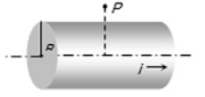
Ager solid infinite wire hai to pure volume me current jayegi to maan lijiye ki total current i hai to center axis se r duri pr point P pr amperian loop assume karte hai. According to ampere’s law
∮→B.→dl=μoi
∮B.dlcosθ=μoi
∮B.dlcos0∘=μoi
B∮dl=μoi
B×2πr=μ0×i
B=μ0i2πr
Ab ager solid current carrying conductor ke ander r duri pr magnetic field nikale to is baar sari current ampere loop se nahi ja rahi hai kyunki pure volume me current flow ho ry hai. Iske liye hum unit area me current nikalenge
πR2→i
1=iπR2
Ampere loop ke area se jaane wali current ho jayegi
iin=iπR2.πr2
B×2πr=μ0×iin
B=μ0i2πrr2R2
B=μ0ir2πR2
Solid cylinder ke surface pr magnetic field hoga
B=μ0i2πR
OMR (One Minute Revision)
- * Ampere ‘s Law states that for a closed curve of length C, magnetic field (B) is related to current (IC): ∮CBdℓ=μ0IC. In this equation, dl represents the differential of length of wire in the curved wire, and μ0 is the permeability of free space.
* Ampere’s Law can be related to the Biot-Savart law, which holds for a short, straight length of conductor: dB=μ04πIdl×rr3. In this equation, partial magnetic field (dB) is expressed as a function of current for an infinitesimally small segment of wire (dl) at a point r distance away from the conductor.
* After integrating, the direction of the magnetic field according to the Biot-Savart Law can be determined using the right hand rule.
* The magnetic field created by current following any path is the sum (or integral) of the fields due to segments along the path (magnitude and direction as for a straight wire), resulting in a general relationship between current and field known as Ampere’s law.
EXAMPLE 7
Describe the motion of a charged particle in a cyclotron if the frequency of the radio frequency (rf) field were doubled.
Here, the condition of magnetic resonance is violated.
When the frequency of the radio Frequency (rf) field was doubled, the time period of the radio frequency (rf) field was halved. Therefore, the duration in which a particle completes half revolution inside the dees, radio frequency completes the cycle. Hence, particles will accelerate and decelerate alternatively. So, the radius of path in the dees will remain the same.
POINT 3
Biot-Savart Law :
This law enables us to calculate the magnitude and direction of the magnetic field produced by a current in a wire. The Biot-Savart law states that at any point P, the magnetic field d→B due to an element →dl of a current-carrying wire is given by d→B=μ04πI→dl׈rr2
Definition of Ampere’s Circuital Law :
Ampere’s circuital law states that the line integral of the magnetic field →B around any closed path is equal to μ0 (permeability constant) times the total current I passing through closed path.
∮→B.→dl=μoI
Net current inside the closed loop.
EXAMPLE 8
An electron enters with a velocity v=v0ˆi into a cubical region (faces parallel to coordinate planes) in which there are uniform electric and magnetic field. The orbit of the electron is found to spiral down inside the cube in plane parallel to the x-y plane. Suggest a configuration of fields E and B that can lead to it.
Considering magnetic field B=B0ˆk, and an electron enters with a velocity v=v0ˆi and a cubical region (Faces parallel to coordinate planes.)
The force on electron, using magnetic lorentz force, is given by
F=−e(v0ˆi×B0ˆk)=ev0B0ˆi
Which revolves the electron in x-y plane.
The electric force F=−eE0ˆK accelerates e along z-axis which in turn increases the radius of circular path and hence particle traversed on spiral path.
EXAMPLE 6
A charged particle of charge e and mass m is moving in an electric field →E and magnetic field →B. Constant dimensionless quantities and quantities of dimention [T]−1.
No dimensionless quantity can be constructed using given quantities.
For a charge particle moving perpendicular to the magnetic field, the magnetic lorentz Forces provides necessary centripetal force for revolution.
mv2R=qvB
On simplifying the terms, we have
∴qBm=vR=ω
Finding the dimensional formula of angular frequency
∴[ω]=[qBm]=[vR]=[T]−1
This is the required expression.
EXAMPLE 9
A charged particle of charge e and mass m is moving in an electric field E and magnetic field B. Construct dimensionless quantities and quantities of dimension [T]−1.
No dimensionless quantity can be constructed using given quantities.
For a charge particle moving perpendicular to the magnetic field, the magnetic lorentz Forces provides necessary centripetal force for revolution.
mv2R=qvB
On simplifying the terms, we have
∴qBm=vR=ω
Finding the dimensional formula of angular frequency
∴[ω]=[qBm]=[vR]=[T]−1
This is the required expression.
EXAMPLE 7
Do magnetic forces obey Newton's third law. Verify for two current elements d→l1=dlˆi located at the origin and d→l2=dlˆj located at (0, R, 0). Both carry current I.
In Biot-savart's law, magnetic field B is parallel (II) to ×r and idl have its direction along the direction of flow of current.
Here. For the direction of magnetic field At dl2, located at (0,R,0) due to wire d1 is given by B∣∣×r or ˆi׈j (because poiint (0,R,0) lies on y-axis), but ˆi׈j=ˆk
So, the direction of magnetic field at d2 is along z-direction.
The direction of magnetic force exerted at d2 because of the first wire along the x-axis F=i(I×B) i.e., F∣∣(i×k) or along −ˆj direction.
Therefore, force due to dl1 on dl2 is non-zero.
Now, for the direction of magnetic field At d1, located at (0,0,0) due to wire d2 is given by B∣∣×r or ˆj×−ˆj (because origiin lies on y-direction w.r.t. point (0,R,0), but j×−ˆj=0
So, the magnetic field at d1 does not exist.
Force due to dl2 on dl1 is zero.
So, magnetic forces do not obey newton's third law.
MAGNETIC FIELD DUE TO A CURRENT ELEMENT, BIOT-SAVART LAW
Tufani law - Jo kahani aapne pehle chapter me coulomb’s law se sikhi thi ki point charge kitna force lagayega. Isi tarah magnetism me biot savart's law hota hai. Biot Savart's law ye btata hai ki ek current element se kitna magnetic field banta hai. Coulomb's law me baat ki gai thi point charge ki aur yaha pr baat karenge current element ki.
Abhi humne samjha ki magnetic field current se banta hai lekin kitna banta hai? Jo current limit hai Idl ye hai current element. Ye chhota sa current hai aur dl bht hi small length of conductor hai jisko point tukda samjh lijiye. Jab current ko wire me flow karayenge tb magnetic field produce hogi. Current flow hone ke baad wire ka dl element liya hai jiska direction current I ke hi direction me lete hai. Is dl se Idl hi current element hai. Jaise ki coulomb’s law point charge ke liye tha usi tarah se Idl current element kitna magnetic field banayega yahi biot savart’s law ne diya ye magnetism ke liye basic law hai jo bht important hai.
We assume that this field is made up of contributions from different segments of the conductor, called current elements. A current element is denoted by Idl, and has the same direction as that of current I.

Current ke flow hone se koi point P lete hai jaha pr magnetic field d→B ban raha hai wo is current element ke chhote chhote tukde jo magnetic field bana rahe hai un sbka sum hai. is point magnetic field inward hai isliye ise humne × se show kiya hai.
dl and Idl ka direction same hoga. Chhota sa current element chhota sa magnetic field banayegi. Ye chhota sa magnetic field kitna banega yahi Biot savart’s law se milti hai.
dB=μ04π.Idlsinθr2
sinθ means current element se point P kitna angle (θ) bna raha hai. Wire se point P ki distance r hai jiski direction jis point pr magnetic field nikalna hai uske along hogi. So, magnetic field
d→B=μ0I4π.→dl×→r|→r|3
μ0=4π×10−7TA−1m
Magnetic field vector quantity hai.
- Direction of Idl kis taraf hota hai? dl×r ka mtlb vector law se vector product nikalte the cross product right hand palm rule se palm ko aise set karna jaise ki palm r ki taraf mude to dl aur r ki direction hatheli mud jati hai. Kyuki ab thumb ander taraf hai to yahi direction of magnetic field ho jata hai. Magnetic field ki direction ander ki tarf ho to use × se show karte hai.
Magnitude of magnetic field is
dB=μ0i4π.dl.rsinθr3
Magnetic field ki unit Wb/m2 ya Tesla hoti hai.
- × ka mtlb hai magnetic field ki direction inside the plane hogi aur ⋅ ka mtlb hai magnetic field ki direction outside the plane hogi. (shown in below figure)

FIELD DUE TO A STRAIGHT CURRENT WIRE

Ek straight wire hai aur is wire se perpendicular d duri pr magnetic field nikalna hai. Ise hum ampere circuital law se bhi proof karenge but usse pehle hum yaha pr biot savart law ka use karke proof karte hai. d duri pr jis point pe hume magnetic field nikalna hai us point se straight conductor ka 1st end point θ1 angle pr aur 2nd end θ2 angle pr lete hai. θ1 clockwise direction me upper end se angle bana raha hai. Aur θ2 anticlockwise direction me lower end se angle banata hai. Biot savart’s law se humne samjha ki kisi current element ki wajah hum magnetic field likh sakte hai chahe long straight wire ho ya koi loop.
d→B=μ04π→dl×→r|→r|3
dB yaha pr biot savart ke according element dy ke liye r duri pr magnetic field hai r vector ka head waha pr hoga jis point pr hume magnetic field nikalna hai. Element dy point se dthη angle bna raha hai .
dB=μ0i4π.dy.rsin(90+θ)r3
dB=μ0i4π.dy.cosθr2
Ye chhote se element ka magnetic field hai. Small element ko hum kahi bhi le sakte hai jiske liye variables hai θ aur r. Do variables ke sath integration karke whole wire ke liye magnetic field nikalna bht complex hoga isliye do variables ko hata ke single variable lane ke liye hum lete hai
tanθ=yd
y=dtanθ
dydθ=dsec2θ
dy=dsec2θdθ
cosθ=dr
r=dsecθ
ye dy aur r ki value ko hum magnetic field ke eq. mein put karte hai
dB=μ0i4π.(dsec2θdθ).cosθ(dsecθ)2
∫dB=∫θ1−θ2μ0i4πd.cosθdθ
B=μ0i4πd∫θ1−θ2cosθdθ
B=μ0i4πd[sinθ]θ1−θ2
B=μ0i4πd[sinθ1−sin(−θ2)]
B=μ0i4πd[sinθ1+sinθ2]
When the point P is on the perpendicular bisector
Is case me θ1 aur θ2 equal honge isliye B ke liye eq. ho jayegaB=μ0i4πd[sinθ+sinθ]
B=μ0i4πd2sinθ
B=μ0i2πdsinθ
Infinitely long wire
Ager wire infinitely long wire hui to d duri pe kisi point pr magnetic fieldB=μ0i4πd[sin90∘+sin90∘]
B=μ0i4πd[1+1]
B=μ0i4πd[2]
B=μ0i2πd
When the point lies along the length of wire (but not on it)
Koi wire jisme current ja ry ho I, ab is wire ke along point P pr magnetic field zero hoga.
MAGNETIC FIELD ON THE AXIS OF A CIRCULAR CURRENT LOOP
Koi loop hai jiske centre se hume magnetic field nikalna hai. Sbse phle hum ek chhota sa element top most point me le lete hai jisme current ki direction figure me show ki gai hai.
Ab ager is current element ke karan point P pr joki r duri me hume magnetic field nikalna ho to
dl aur r ke bich ka angle sinθ hai jisme θ=90∘ hai. Vector aur magnetic field ki direction hum thik usi tarah nikalenge jaise humne biot savart’s law ke liye nikali thi right hand palm rule (thappad rule) se vector ki direction point P ke along aur magnetic field B ki direction vector r ke direction ke perpendicular hogi jaise ki aap figure me dekh sakte hai.
dB=μ0I4πdlrsinθr3
because θ=90∘ and sinθ=1
So,
dB=μ0.I4πdlr2
jaise element uper hai vaisa hi ek element lower me (dl’) bhi hai to is element ke liye magnetic field
dB’=μ0.I4πdlr2
dl’ element ke liye current ki direction ander ki taraf hai isliye magnetic field dB’ ki direction niche ki tarah figure me dikhaya anusar hogi. Magnetic field dl aur r dono ke perpendicular hoga. Isliye dB aur dB’ ke components lenge kyon ki direction me magnetic field ka component dBcosθ hoga. Pure circular current loop ke liye magnetic field nikalne ke liye hum small element ke magnetic field ka integration kr denge.
⇒∫dBcosθ=μ0.I4πdlcosθR2+x2
where r=√R2+x2 and OP=x
⇒∫dBcosθ=μ0.I4π(R2+x2)R√R2+x2dl
where cosθ=R√R2+x2 hai.
So, B=∫μ0.IR4π(R2+x2)32dl
B=μ0.IR4π(R2+x2)32∫dl
B=μ0.IR4π(R2+x2)322πR
B=μ0.IR22(R2+x2)32
Yahi circular loop se point P pr magnetic field B hai. Ager hume is circular loop ke center pr magnetic field nikalna ho to OP=x=0 ho jayega jisse magnetic field
B=μ0.IR22(R2+02)32
B=μ0IR22R3
B=μ0I2R
Yahi circular loop ke center pr magnetic field hai. x=0 ke liye magnetic field ki value maximum hogi. Niche figure me aap circular loop ke liye magnetic field lines and graph dekh sakte hai.

Field at the Centre of a Current Arc

B=μ0i4πRθ
Field at the Centre of a Current Semicircle

B=μ0I4πRπ
B=μ0I4R
where θ=π because for semicircle angle θ=180∘
Field at the Centre of a Current Circle

B=μ0I4πR2π
where θ=2π because for circle angle θ=360∘
AMPERE’S CIRCUITAL LAW
Jaise aapne chapter 1 me phle aapne coulomb’s law padha fr gauss law padha. Coulomb's law se force ke karan electric field and flux jo create hota hai use gauss law bade aasani se easily find kr deta hai but uske liye condition thi ki symmetric formation honi chaiye isi tarah yaha magnetism me biot savart's law jo magnetic field nikalta hai usse bade hi easy way me ampere circuital law find kr deta hai. Jo kam gauss law ne coulomb’s law ke liye electrostatics me kiya tha more or less wahi kaam ampere circuital law kr raha hai yaha pr biot savart’s law ke liye.Ampere’s circuital law states that the line integral of the magnetic field →B around any closed path is equal to μ0 (permeability constant) times the total current I passing through closed path.
∮→B.→dl=μoI
Net current inside the closed loop.
Kisi unit area se gujarne wali magnetic field lines hai →B.→dl
dl line vector hai jisko close karte hai to closed loop milta hai. Closed loop ke liye →B.→dl barabar hoga μ0 aur loop me jitni current hai uske.

Uper diye gaye figure me aap dekh sakte hai jaha humne ek lamba current carrying conductor ke around ager magnetic field nikalna hai to hume ek closed circular path lena hota hai. Ab ye closed circular path conductor se r radius pr hai. Ab conductor ke around magnetic field nikalne ke liye line integral dl lenge means circular path ka chhota chhota hissa jisse milkr circular path bana hai. Closed path me line integral ke liye magnetic field B ki value path ke ander flow hone wale net current ke μ0 times hota hai. Yahi ampere’s circuital law hai. →B.→dl ke liye direction kisi bhi line integral ke along →B.→dl jaha positive aara hai us direction ki current ko hum positive lelenge. →B.→dl same direction me honge to current positive aur ager →B.→dl opposite direction me honge to current ko lenge negative.
The circular sign in the equation means that the scalar product B.dl is to be integrated around the closed loop known as the Amperian loop whose beginning and end point are the same.
Yaha pr dl humne anticlock wise maana hai kyuki current jo uper ja ry hai uske karan magnetic field bhi tangential hai aur chhota sa dl bhi tangential hai to ∮B.dlcos0=μ0Iin
yaha pr Iin mtlb jo loop ke ander current aary hai. Sare chhote chhote elements ko jodne se circle ka circumference (2πr) ban jayega.
B∮.→dl=μ0Iin
B(2πr)=μ0Iin
B=μ0Iin2πr
Ager current ki direction negative ho to magnetic field bhi negative ho jayega.
Ampere’s law to a infinite straight conductor
Magnetic field for current carrying conductorB=μ0I2πr

B is the magnetic field due to current carrying conductor at point P.
Maana ki koi infinite current carrying conductor hai jiske paas P point pr hume magnetic field nikalni hai to ek circular loop bana lete hai jo conductor se r radius pr hai. According to Ampere’s law
∮→B.→dl=μoI
Point P pr right hand thumb rule se tangentially magnetic field B ka direction aur dl ka direction bhi P point se tangential hi hoga isliye B aur dl ke bich circular loop ke hr point pr angle zero hoga.
∮B.dlcosθ=μoI
∮B.dlcos0∘=μoI
B∮dl=μoI
B×2πR=μ0×I
B=μ0I2πR
- Magnetic field line humesha close loop me exist karti hai isliye net flux through a closed surface zero hota hai. Is tarah se gauss law magnetism me hamesha zero hota hai.
Hollow Current Carrying Infinitely Long Cylinder : (I is uniformly distributed on the whole circumference)

Kisi hollow cylinder ke sirf surface pr current flow hogi. Hume is cylinder ke karan magnetic field nikalna hai. Cylinder ke axis ke center se r duri pe magnetic field find out karna hai. r duri me ek loop lenge jise bolenge amperian loop aur ise anticlockwise lenge. Amperian loop ke ander total current i hai. According to ampere’s law
∮→B.→dl=μoi
∮B.dlcosθ=μoi
∮B.dlcos0∘=μoi
B∮dl=μoi
B×2πr=μ0×i
B=μ0i2πr
Ager cylinder ke ander magnetic field nikalna chahe to

Magnetic field ke ander center se r duri pe magnetic field nikalna chahe to isme se gujarta hua amperian loop bana lenge. Sari current to surface se hoker ja ry hai isiliye hollow cylinder ke ander magnetic field zero hota hai.
∮→B.→dl=μoi
because i=0 so, ∮→B.→dl=0
Solid Infinite Current Carrying Cylinder

Ager solid infinite wire hai to pure volume me current jayegi to maan lijiye ki total current i hai to center axis se r duri pr point P pr amperian loop assume karte hai. According to ampere’s law
∮→B.→dl=μoi
∮B.dlcosθ=μoi
∮B.dlcos0∘=μoi
B∮dl=μoi
B×2πr=μ0×i
B=μ0i2πr
Ab ager solid current carrying conductor ke ander r duri pr magnetic field nikale to is baar sari current ampere loop se nahi ja rahi hai kyunki pure volume me current flow ho ry hai. Iske liye hum unit area me current nikalenge
πR2→i
1=iπR2
Ampere loop ke area se jaane wali current ho jayegi
iin=iπR2.πr2
B×2πr=μ0×iin
B=μ0i2πrr2R2
B=μ0ir2πR2
Solid cylinder ke surface pr magnetic field hoga
B=μ0i2πR
OMR (One Minute Revision)
- * Ampere ‘s Law states that for a closed curve of length C, magnetic field (B) is related to current (IC): ∮CBdℓ=μ0IC. In this equation, dl represents the differential of length of wire in the curved wire, and μ0 is the permeability of free space.
* Ampere’s Law can be related to the Biot-Savart law, which holds for a short, straight length of conductor: dB=μ04πIdl×rr3. In this equation, partial magnetic field (dB) is expressed as a function of current for an infinitesimally small segment of wire (dl) at a point r distance away from the conductor.
* After integrating, the direction of the magnetic field according to the Biot-Savart Law can be determined using the right hand rule.
* The magnetic field created by current following any path is the sum (or integral) of the fields due to segments along the path (magnitude and direction as for a straight wire), resulting in a general relationship between current and field known as Ampere’s law.
EXAMPLE 8
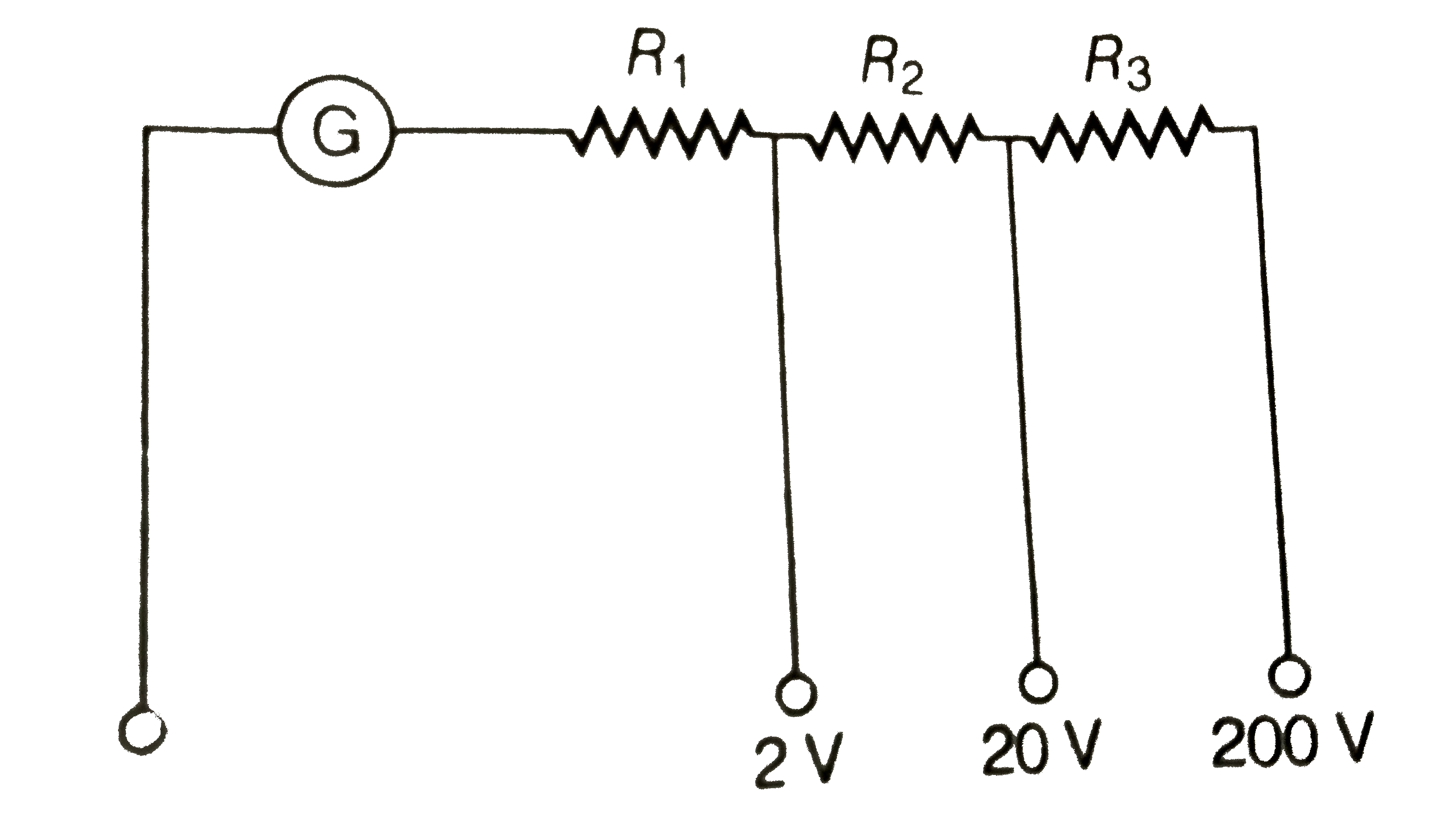
A multirange voltmeter can be constructed by using a galvanometer circuit as shown in figure. We want to construct a voltmeter that can measure 2V, 20V and 200V using a galvanometer of resistance 10Ω and that produces maximum deflection for current of 1mA. Find R1, R2 and R3 that have to be used. 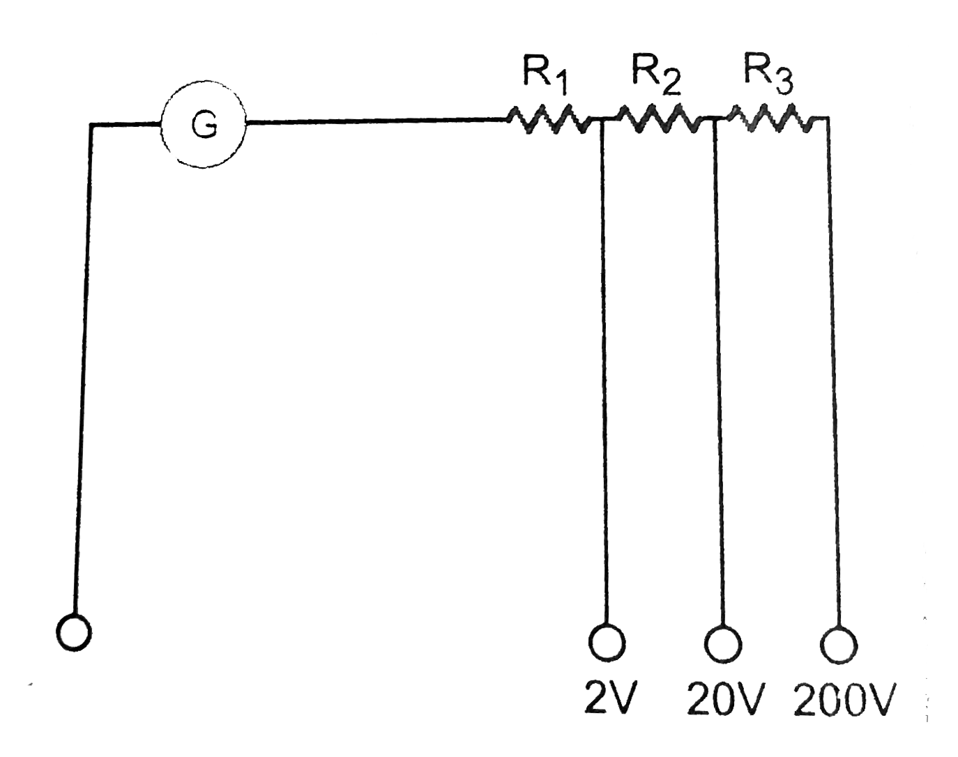
 .
.
Applying expression in different situations ltbr For iG(G+R1)=2 For 2V range
For IG(G+R1+R2)=2 For 20V range ltbr> And for IG(G+R1+R2+R3)=200 For 200V range
On solving we get R1=1990Ω,R2=18kΩandR3=180kΩ
POINT 3
Biot-Savart Law :
This law enables us to calculate the magnitude and direction of the magnetic field produced by a current in a wire. The Biot-Savart law states that at any point P, the magnetic field d→B due to an element →dl of a current-carrying wire is given by d→B=μ04πI→dl׈rr2
Definition of Ampere’s Circuital Law :
Ampere’s circuital law states that the line integral of the magnetic field →B around any closed path is equal to μ0 (permeability constant) times the total current I passing through closed path.
∮→B.→dl=μoI
Net current inside the closed loop.
EXAMPLE 9
Consider a tightly wound 100 turn coil of radius 10 cm, carrying a current of 1 A. What is the magnitude of the magnetic field at the centre of the coil?
Since the coil is tightly wound, we may take each circular element to have the same radius R=10cm=0.1m. The number of turns N=100. The magnitude of the magnetic field is,
B=μ0NI2R
=4π×10−7×102×12×10−1
=2π×10−4
=6.28×10⁻⁴T
EXAMPLE 10
Do magnetic forces obey Newton's third law. Verify for two current elements dl1=dlˆi located at the origin and dl2=dlˆj located at (0,R,0). Both carry current I.
In Biot-savart's law, magnetic field B is parallel (II) to ×r and idl have its direction along the direction of flow of current.
Here. For the direction of magnetic field At dl2, located at (0,R,0) due to wire d1 is given by B∣∣×r or ˆi׈j (because poiint (0,R,0) lies on y-axis), but ˆi׈j=ˆk
So, the direction of magnetic field at d2 is along z-direction.
The direction of magnetic force exerted at d2 because of the first wire along the x-axis F=i(I×B) i.e., F∣∣(i×k) or along −ˆj direction.
Therefore, force due to dl1 on dl2 is non-zero.
Now, for the direction of magnetic field At d1, located at (0,0,0) due to wire d2 is given by B∣∣×r or ˆj×−ˆj (because origin lies on y-direction w.r.t. point (0,R,0), but j×−ˆj=0
So, the magnetic field at d1 does not exist.
Force due to dl2 on dl1 is zero.
So, magnetic forces do not obey newton's third law.
EXAMPLE 10
Figure shows a long straight wire of a circular cross-section (radius a) carrying steady current I. The current I is uniformly distributed across this cross-section. Calculate the magnetic field in the region r<a and r>a.
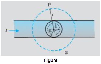
(a) Consider the case r>a. The Amperian loop, labelled 2, is a circle concentric with the cross-section. For this loop,
L=2πr
Ie= Current enclosed by the loop =I
The result is the familiar expression for a long straight wire
B (2π r) = µ_0 I
B=μ0I2πr
B∝1r (r>a)
(b) Consider the case r<a. The Amperian loop is a circle labelled 1. For this loop, taking the radius of the circle to be r,
L=2πr
Now the current enclosed Ie is not I, but is less than this value. Since the current distribution is uniform, the current enclosed is,
Ie=I(πr2πa2)=Ir2a2
Using Ampere’s law,
B(2πr)=μ0Ir2a2
B=(μ0I2πa2)r
B∝r (r lt a)
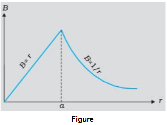
Above figure shows a plot of the magnitude of B with distance r from the centre of the wire. The direction of the field is tangential to the respective circular loop (1 or 2) and given by the right-hand rule described earlier in this section.
This example possesses the required symmetry so that Ampere’s law can be applied readily.
EXAMPLE 11
An element Δl=Δxˆi is placed at the origin and carries a large current I=10A (Fig.). What is the magnetic field on the y-axis at a distance of 0.5m. Δx=1cm.?
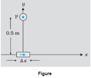
|dB|=μ04πIdlsinθr2
dl=Δx=10−2m,
I=10A, r=0.5m=y
μ04π=10−7Tm/A
θ=90° ; sinθ=1
=4×10⁻⁸T
The direction of the field is in the +z-direction. This is so since,
dl×r=Δxˆi×yˆj=yΔx(ˆi׈j)=yΔxˆk
We remind you of the following cyclic property of cross-products,
ˆi׈j=ˆk;
ˆj׈k=ˆi;
ˆk׈i=ˆj
Note that the field is small in magnitude.
EXAMPLE 11
A long straight wire carrying current of 25A rests on a table as shown in figure. Another wire PQ of length 1m, mass 2⋅5g carries the same current but in the opposite direction. The wire PQ is free to slide up and down. To what height will PQ rise?
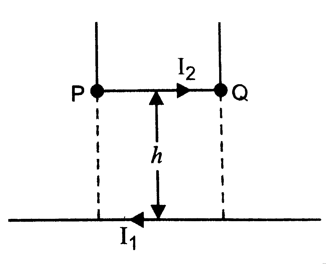
The magnetic field produced by long straight wire carrying current of 25A rests on a table on small wire B=μ0I2πh
the magnetic force on small conductor is
F=Bilsinθ=Bil
Force applied on PQ balance the weight of small current carrying wire.
F=mg=μ0I2l2πh
h=μ0I2l2πmg=4π×10−7×25×25×12π×2.5×10−3×9.8=51×10−4
h=0.51cm
EXAMPLE 12
A straight wire carrying a current of 12 A is bent into a semi-circular arc of radius 2.0 cm as shown in Fig.(a). Consider the magnetic field B at the centre of the arc. (a) What is the magnetic field due to the straight segments? (b) In what way the contribution to B from the semicircle differs from that of a circular loop and in what way does it resemble? (c) Would your answer be different if the wire were bent into a semi-circular arc of the same radius but in the opposite way as shown in Fig.(b)??
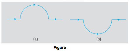
(a) dl and r for each element of the straight segments are parallel. Therefore, dl×r=0.
Straight segments do not contribute to |B|.
(b) For all segments of the semicircular arc, dl×r are all parallel to each other (into the plane of the paper). All such contributions add up in magnitude. Hence direction of B for a semicircular arc is given by the right-hand rule and magnitude is half that of a circular loop. Thus B is 1.9×10⁻⁴T normal to the plane of the paper going into it.
(c) Same magnitude of B but opposite in direction to that in (b).
EXAMPLE 12
A 100 turn rectangular coil ABCD (in XY plane) is hung from one arm of a balance (figure). A mass 500g is added to the other arm to balance the weight of the coil. A current 4⋅9A passes through the coil and a constant magnetic field of 0⋅2T acting inward (in xz plane) is switched on such that only arm CD of length 1cm lies in the field. How much additional mass 'm' must be added to regain the balance?
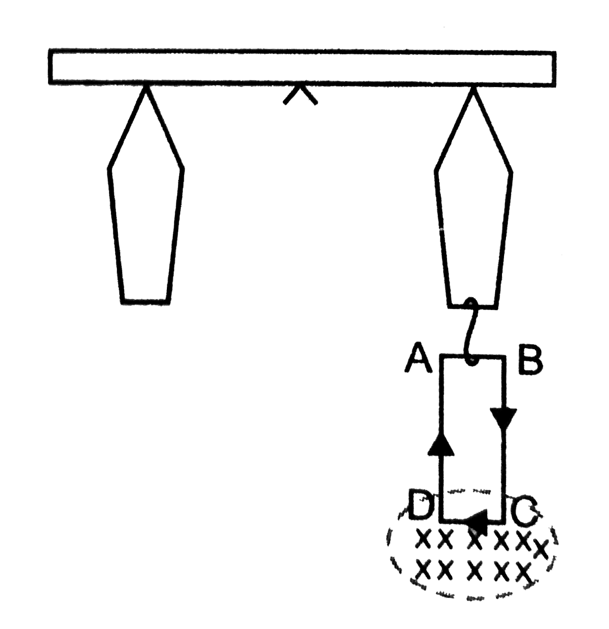
For equilibrium/balance, net torque should also be equal to zero
When the field is off ∑t=0 considering the separation of each hung from mid-point be l
Mgl=Wcoill
500gl=Wcoill
Wcoil=500×9.8N
Taking moment of force about mid-point, we have the weight of coil
When the magnetic field is switched on
Mgl+mgl=Wcoill+IBLsin90∘I
mgl=BILl
m=BILg=0.2×4.9×1×10−29.8=10−3kg=1g
Thus, 1 g of additional mass must be added tor eagin the balance.
EXAMPLE 13
Consider a tightly wound 100 turn coil of radius 10 cm, carrying a current of 1 A. What is the magnitude of the magnetic field at the centre of the coil?
Since the coil is tightly wound, we may take each circular element to have the same radius R=10cm=0.1m. The number of turns N=100. The magnitude of the magnetic field is,
B=μ0NI2R
=4π×10−7×102×12×10−1
=2π×10−4
=6.28×10⁻⁴T
THE SOLENOID AND THE TOROID
The solenoid
Solenoid form karne ke liye ek insulated long wire lenge jise cylindrical shape pr round round lapet denge jaise figure me dikhaya gaya hai. Ye spring ke jaise hi helical shape me hogi. Solenoid banane ke liye solenoid ka length radius se jyada hone chahiye. Solenoid ke ander more or less uniform current milta hai. Solenoid ke ander magnetic field magnetic fieldB=μ0nI
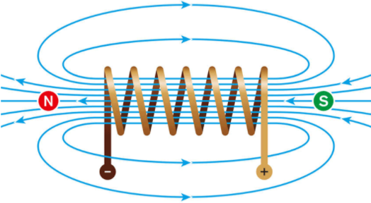
Solenoid ke surface pr magnetic field
B=μ0nI2
n=Nl number of turns per unit length.
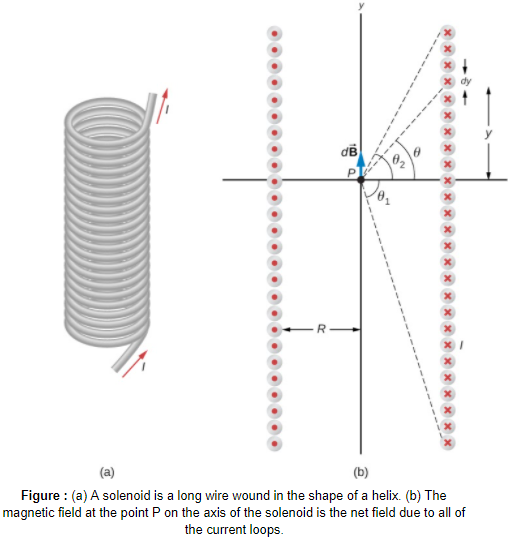
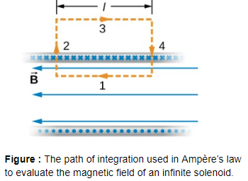
Is solenoid ke ander magnetic field find karne ke liye humne yaha pr solenoid ko half cut karke uper figure me show kiya hai jaha magnetic field ki direction left side me show ki gai hai kyuki current uper wale surface me ander ki taraf ja ry hai aur niche wale surface se baher ki taraf aa rahi hai. Ab hum is surface pe amperian loop lenge jaisa ki uper figure me show kiya gaya hai (sides 1, 2, 3, 4). Ab hume yaha dl ki direction define karni hai wo bhi aise ki →B.→dl zero aani chahiye. Ampere circuital law se kisi solenoid ke liye magnetic field derive karne ke liye ye sabse easiest method hai. Hume ampere loop ka shape symmetrical shape me lena hota hai isliye hum ise bol sakte hai rectangular loop le rahe hai. Humare paas 4 part hai is loop ke liye to in charo part ke liye hum →B.→dl lenge.
∮→B⋅→dl=∫1→B⋅→dl+∫2→B⋅→dl+∫3→B⋅→dl+∫4→B⋅→dl
Rectangle ke 1st part ke liye →B.→dl hi hoga kyuki →B aur →dl same direction me hai. Rectangle ke 2nd part ke liye →B.→dlcos90∘=0 hoga kyuki →B aur →dl ek dusre ke perpendicular hai. Jo current solenoid se flow ho rahi hai wo current rectangle ke sirf 1st aur 2nd and 4th ke only half portion ko cover kr rahi hai. Rectangle ke 3rd part ke liye →B.→dl=0 hoga kyuki rectangle ke is part se koi current flow nahi ho rahi hai. Rectangle ke 4th part ke liye →B.→dlcos90∘=0 hoga kyuki →B aur →dl ek dusre ke perpendicular hai. Is prakar hume hume yaha pr →B.→dl ki value kevel rectangle ke 1st part ke liye mili to hum likh sakte hai
∮→B⋅→dl=μ0iin
No. of turns per unit length =n to l length ke liye number of turns honge nl Ab ek loop se current aati hai I to l lop se current ho jayegi nlI isliye magnetic field ho jayega
Bl=μ0nlI
B=μ0nI
Ye kisi solenoid ke liye magnetic field ki value hai.
The Toroid
Jab kisi tire shaped material me conducting wire ko lapet de ya fr kisi long solenoid ke dono end ko hi aapas me aise jode jiska koi end na ho to ise toroid kahte hai. Is toroid ke ander hi magnetic field milta hai jo solenoid ke ander magnetic field ke equal hota hai.B=μ0nI
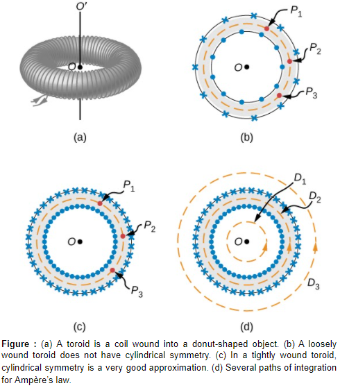
Toroid ke bich se gujarta hua ek amperian loop lete hai jiske liye ampere current Iin hai. Ab ager hum current ki direction ko clockwise lete hai to toroid ke ander wale hisse me dot ban jaye kyunki current ander ki taraf ja ry hai (shown in figure b).
∮→B⋅→dl=μ0Iin
kyuki B aur dl same direction me hai isiliye ∮B⋅dlcos0=μ0Iin
kyuki chhote chhote element se milkr amperian loop bana hai to amperian loop ke liye circumference 2πr hogi aur toroid me total number of turns N honge. So,
B.2πr=μ0Ni
B=μ0NI2πr
n=N2πr= No. of turns per unit length.
Ager hum toroid me lapete huye wire ko bht paas paas lapet de to amperian loop me current Iin increase ho jayega (shown in figure c).
Ab ager hum toroid ke ander r duri pr magnetic field nikale to magnetic field zero hoga isi tarah ager toroid ke baher r’ duri pr magnetic field bhi zero hi hoga. Kyuki jab hum r aur r’ duri amperian loop draw kare to is amperian loop se gujarne wali current zero hai isiliye Iin=0 hai (shown in figure d).
Magnetic Force On A Moving Charge In Magnetic Field
The electric charges moving in a magnetic field experience a force, while there is no such force on static charge. Ager kisi bhi charge q ko magnetic field B me v velocity chhoda jaye to moving charge ke uper force lagta hai.F=qvBsinθ Magnetic lorentz force
Magnetic force, moving charge ki velocity aur magnetic field ke perpendicular hoga.
Isliye force ki direction v×B ke direction me hogi. θ charge ki velocity V aur magnetic field B ke bich me angle hai. Moving charge magnetic field me jayega to usme force lagega.
- * Magnetic force magnetic field ke perpendicular hota hai jabki electric force electric field ke direction me hoti hai.
* Magnetic force instant displacement ke perpendicular hai isliye work done by magnetic force hamesha zero hota hai.
* Magnetism me velocity ka magnitude change nahi hota sirf direction change hoti hai, jisse circular motion hota hai.
* Jab magnetic field B aur velocity v same direction me aur parallel ho to moving charge me koi force nahi lagta.
OMR (One Minute Revision)
- * Loops of wire in a magnetic field create current.
* Electromagnetism is the use of electric current to make magnets. Electromagnets are temporary magnets which keep their magnetic properties only when current is passing through them.
* Solenoids and electromagnets have many uses in physics and engineering because they allow the control of magnetic fields.
* The magnetic field strength inside a solenoid is B=μ0nI (inside a solenoid) where n is the number of loops per unit length of the solenoid. The field inside is very uniform in magnitude and direction.
EXAMPLE 14
Figure shows a long straight wire of a circular cross-section (radius a) carrying steady current I. The current I is uniformly distributed across this cross-section. Calculate the magnetic field in the region r<a and r>a.

(a) Consider the case r>a. The Amperian loop, labelled 2, is a circle concentric with the cross-section. For this loop,
L=2πr
Ie= Current enclosed by the loop =I
The result is the familiar expression for a long straight wire
B(2πr)=µ0I
B=μ0I2πr
B∝1r (r>a)
(b) Consider the case r<a. The Amperian loop is a circle labelled 1. For this loop, taking the radius of the circle to be r,
L=2πr
Now the current enclosed Ie is not I, but is less than this value. Since the current distribution is uniform, the current enclosed is,
Ie=I(πr2πa2)=Ir2a2
Using Ampere’s law,
B(2πr)=μ0Ir2a2
B=(μ0I2πa2)r
B∝r (r lt a)

Above figure shows a plot of the magnitude of B with distance r from the centre of the wire. The direction of the field is tangential to the respective circular loop (1 or 2) and given by the right-hand rule described earlier in this section.
This example possesses the required symmetry so that Ampere’s law can be applied readily.
POINT 4
Solenoid :
A long wire wound in the form of a helical coil is known as a solenoid.
Toroid :
If a solenoid is bent in a circular shape and the ends are joined, we get a toroid. Alternatively, one can start with a nonconducting ring and wind a conducting wire closely on it. The magnetic field in such a toroid can be obtained using Ampere's Law.
EXAMPLE 15
A current carrying loop consists of 3 identical quarter circles of radius R, lying in the positive quadrants of the x-y,y-z and z-x planes with their centres at the origin, joined together. Find the direction and magnitude of B at the origin.
For the current carrying loop quarter circles of radius R, lying in the positive quadrants of the x-y plane
B1=μ04πI(π/2)Rˆk=μ04I2Rˆk
For the current carrying loop quarter circles of radius R, lying in the positive quadrants of the y-z plane
B2=μ04I2Rˆi
For The current carrying loop quarter circles of radius R, lying in the positive quadrants of the z-x plane
B3=μ04I2Rˆi
Current carrying loop consists of 3 identical quarter circles of radius R, lying in the positive quadrants of the x-y, y-y and z-z planes with their centres at the origin, joined together is equal to the vector sum of magnetic field due to each quarter and given by
B=14π(ˆi+ˆj+ˆk)μ0I2R
EXAMPLE 13
A solenoid of length 0.5 m has a radius of 1 cm and is made up of 500 turns. It carries a current of 5 A. What is the magnitude of the magnetic field inside the solenoid?
The number of turns per unit length is,
n=5000.5=1000turns/m
The length l=0.5m and radius r=0.01m.
Thus, la=50
i.e., l>>a
Hence, we can use the long solenoid formula, namely, Eq.
B=µ0nI
=4π×10–7×103×5
=6.28×10⁻³T
EXAMPLE 16
Consider a circular current-carrying loop of radius R in the x-y plane with centre at origin. Consider the line integral
∑(L)=∣∣∣∫L−LB.dl∣∣∣
take along z-along.
(a). Show that ∑(L) monotonically increases with L
(b) Use an appropriate amperian loop to show that ∑(∞)=μ0I. Where I is the current in the wire
(c). Verify directly the above result
(d). Suppose we replace the circular coil by a square coil of sides R carrying the same current I.
What can you say about ∑(L)and∑(∞) ?
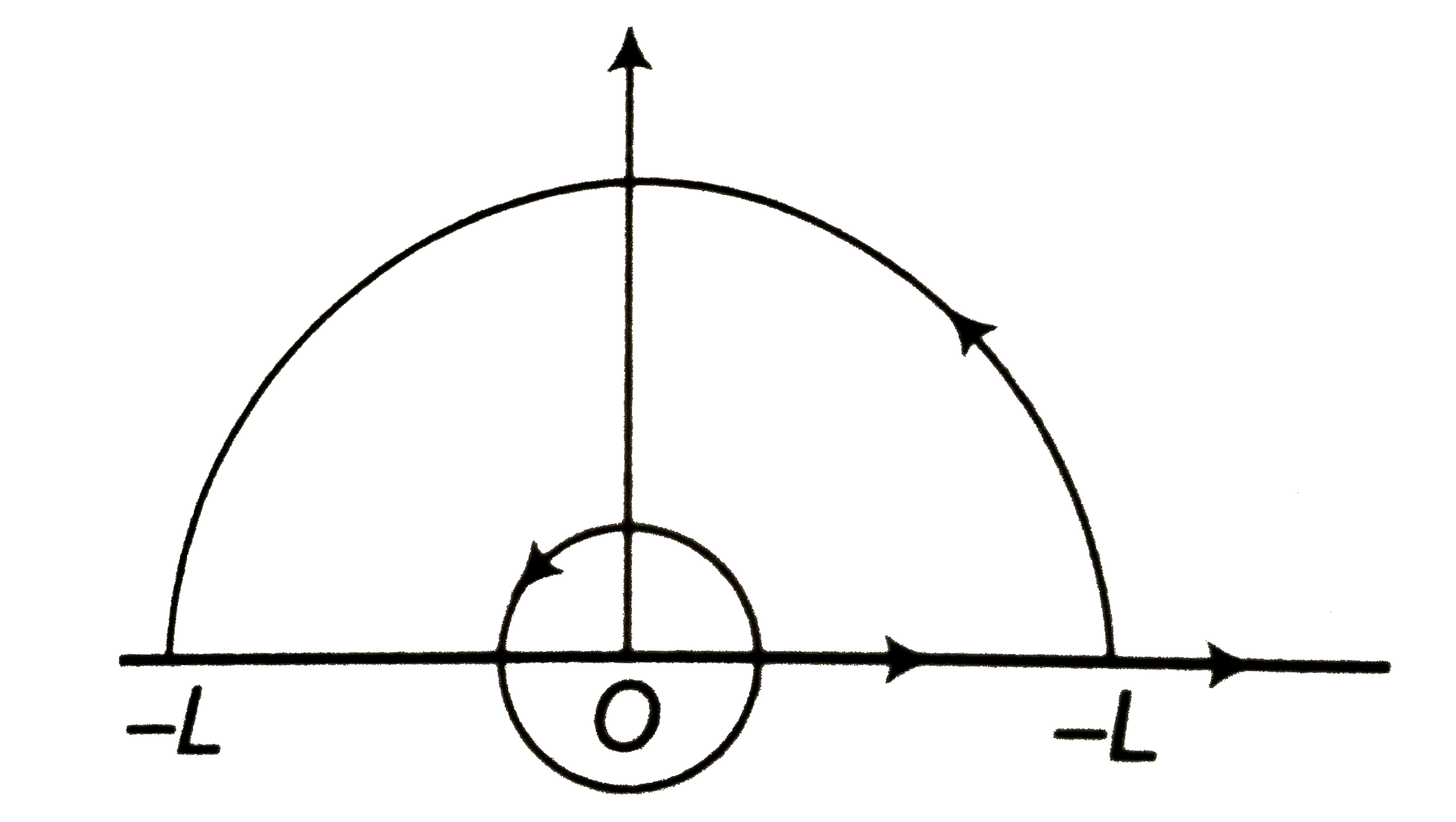
(a). B(z) points in the same direction on z-axis and hence , J(L) is a monotonically function of L. ltbtgt Since B and dl along the same direction, therefore B.dl=B.dl as cos0=1
(b). J(L)+contribution from large distance on contour C=μ0I
Contribution form large distance →0 (as B∝1/r3)
J(∞)−μ0I
(c). the magnetic field due to circular current-carrying loop of radius R in the x-y plane with centre at origin at any point lying at a distance of from origin.
BZ=μ0lR22(Z2+R2)3/2
∫∞−∞BZdz=∫∞−∞μ0lR22(Z2+R2)3/2dz
Put Z=Rtanθ1
⇒dZ=Rsec2θdθ
∴∫∞−∞Bzdz=μ0I2∫π/2−π/2cosθdθ=μ0I
(d). B(Z)square<B(Z)circular coil
∑(L)square<∑(L)circular coil
but by using arguments as in (b)
∑(∞)square=sun(∞)circular
EXAMPLE 14
A rectangular conducting loop consists of two wires on two opposite sides of length l joined together by rods of length d. The wires are each of the same material but with cross-sections differing by a factor of 2. The thicker wire has a resistance R and the rods are of low resistance, which in turn are connected to a constant voltage source V0. The loop is placed in a uniform magnetic field B at 45∘ to its plane. Find τ, the torque exerted by the magnetic field on the loop about an axis through the centres of rods.
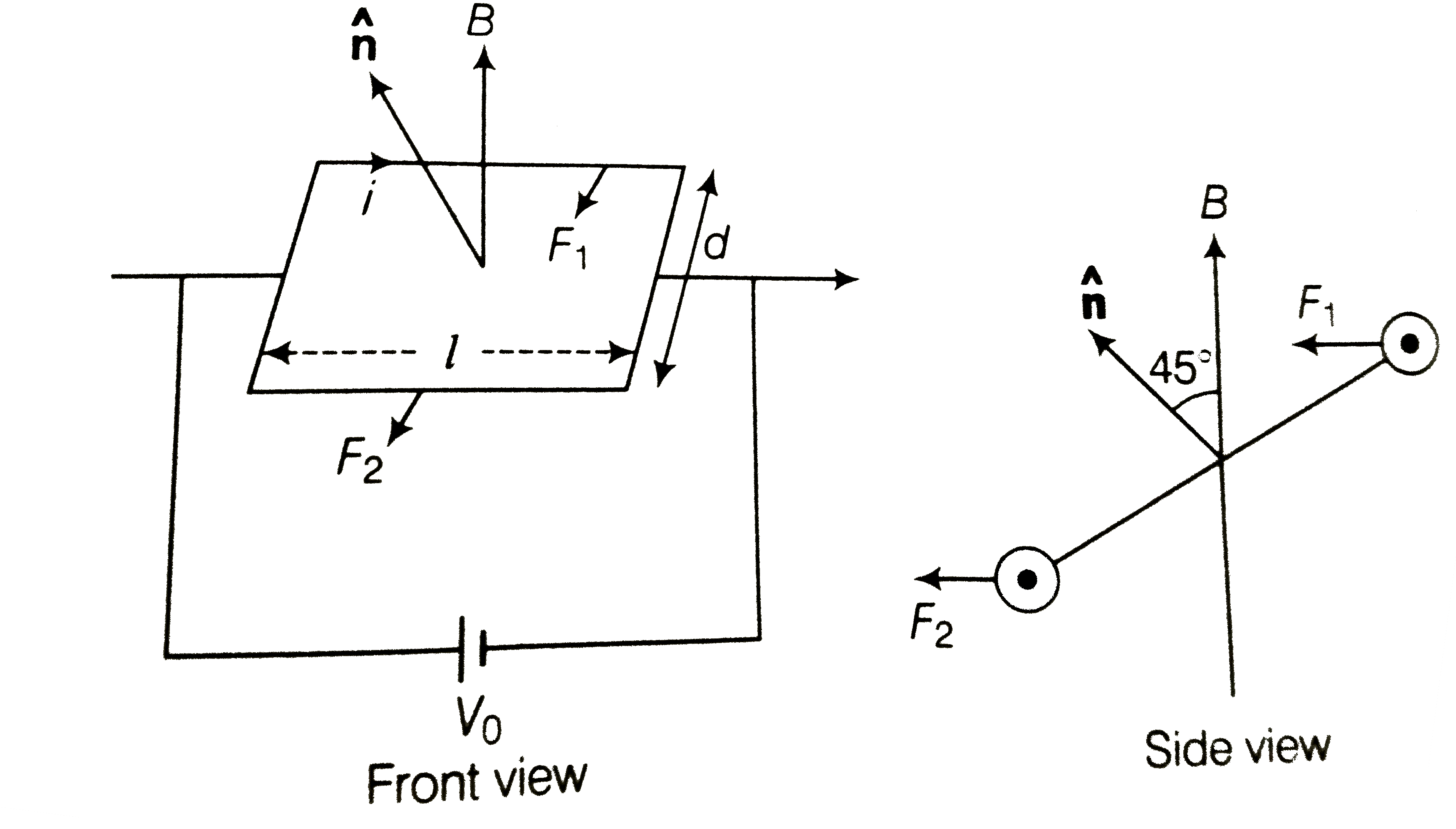
Thicker wire has a resistance R, then the other wire has a resistance 2R as the wires are of the same material but with cross-sections differing by a factor 2.
Now, the force and hence, torque on first wire is given by
F1=i1iB=V02RlB,τ1=d2√2F1=V0ldB2√2R
Similarly, the force hence torque on otehr wire is given by
F2=i2lB=V02RlB,τ2=d2√2F2=V0ldB4√2R
So, net torque τ=τ1−τ2
τ=14√2V0ldBR
THE SOLENOID AND THE TOROID
The solenoid
Solenoid form karne ke liye ek insulated long wire lenge jise cylindrical shape pr round round lapet denge jaise figure me dikhaya gaya hai. Ye spring ke jaise hi helical shape me hogi. Solenoid banane ke liye solenoid ka length radius se jyada hone chahiye. Solenoid ke ander more or less uniform current milta hai. Solenoid ke ander magnetic field magnetic fieldB=μ0nI

Solenoid ke surface pr magnetic field
B=μ0nI2
n=Nl number of turns per unit length.


Is solenoid ke ander magnetic field find karne ke liye humne yaha pr solenoid ko half cut karke uper figure me show kiya hai jaha magnetic field ki direction left side me show ki gai hai kyuki current uper wale surface me ander ki taraf ja ry hai aur niche wale surface se baher ki taraf aa rahi hai. Ab hum is surface pe amperian loop lenge jaisa ki uper figure me show kiya gaya hai (sides 1, 2, 3, 4). Ab hume yaha dl ki direction define karni hai wo bhi aise ki →B.→dl zero aani chahiye. Ampere circuital law se kisi solenoid ke liye magnetic field derive karne ke liye ye sabse easiest method hai. Hume ampere loop ka shape symmetrical shape me lena hota hai isliye hum ise bol sakte hai rectangular loop le rahe hai. Humare paas 4 part hai is loop ke liye to in charo part ke liye hum →B.→dl lenge.
∮→B⋅→dl=∫1→B⋅→dl+∫2→B⋅→dl+∫3→B⋅→dl+∫4→B⋅→dl
Rectangle ke 1st part ke liye →B.→dl hi hoga kyuki →B aur →dl same direction me hai. Rectangle ke 2nd part ke liye →B.→dlcos90∘=0 hoga kyuki →B aur →dl ek dusre ke perpendicular hai. Jo current solenoid se flow ho rahi hai wo current rectangle ke sirf 1st aur 2nd and 4th ke only half portion ko cover kr rahi hai. Rectangle ke 3rd part ke liye →B.→dl=0 hoga kyuki rectangle ke is part se koi current flow nahi ho rahi hai. Rectangle ke 4th part ke liye →B.→dlcos90∘=0 hoga kyuki →B aur →dl ek dusre ke perpendicular hai. Is prakar hume hume yaha pr →B.→dl ki value kevel rectangle ke 1st part ke liye mili to hum likh sakte hai
∮→B⋅→dl=μ0iin
No. of turns per unit length =n to l length ke liye number of turns honge nl Ab ek loop se current aati hai I to l lop se current ho jayegi nlI isliye magnetic field ho jayega
Bl=μ0nlI
B=μ0nI
Ye kisi solenoid ke liye magnetic field ki value hai.
The Toroid
Jab kisi tire shaped material me conducting wire ko lapet de ya fr kisi long solenoid ke dono end ko hi aapas me aise jode jiska koi end na ho to ise toroid kahte hai. Is toroid ke ander hi magnetic field milta hai jo solenoid ke ander magnetic field ke equal hota hai.B=μ0nI

Toroid ke bich se gujarta hua ek amperian loop lete hai jiske liye ampere current Iin hai. Ab ager hum current ki direction ko clockwise lete hai to toroid ke ander wale hisse me dot ban jaye kyunki current ander ki taraf ja ry hai (shown in figure b).
∮→B⋅→dl=μ0Iin
kyuki B aur dl same direction me hai isiliye ∮B⋅dlcos0=μ0Iin
kyuki chhote chhote element se milkr amperian loop bana hai to amperian loop ke liye circumference 2πr hogi aur toroid me total number of turns N honge. So,
B.2πr=μ0Ni
B=μ0NI2πr
n=N2πr= No. of turns per unit length.
Ager hum toroid me lapete huye wire ko bht paas paas lapet de to amperian loop me current Iin increase ho jayega (shown in figure c).
Ab ager hum toroid ke ander r duri pr magnetic field nikale to magnetic field zero hoga isi tarah ager toroid ke baher r’ duri pr magnetic field bhi zero hi hoga. Kyuki jab hum r aur r’ duri amperian loop draw kare to is amperian loop se gujarne wali current zero hai isiliye Iin=0 hai (shown in figure d).
Magnetic Force On A Moving Charge In Magnetic Field
The electric charges moving in a magnetic field experience a force, while there is no such force on static charge. Ager kisi bhi charge q ko magnetic field B me v velocity chhoda jaye to moving charge ke uper force lagta hai.F=qvBsinθ Magnetic lorentz force
Magnetic force, moving charge ki velocity aur magnetic field ke perpendicular hoga.
Isliye force ki direction v×B ke direction me hogi. θ charge ki velocity V aur magnetic field B ke bich me angle hai. Moving charge magnetic field me jayega to usme force lagega.
- * Magnetic force magnetic field ke perpendicular hota hai jabki electric force electric field ke direction me hoti hai.
* Magnetic force instant displacement ke perpendicular hai isliye work done by magnetic force hamesha zero hota hai.
* Magnetism me velocity ka magnitude change nahi hota sirf direction change hoti hai, jisse circular motion hota hai.
* Jab magnetic field B aur velocity v same direction me aur parallel ho to moving charge me koi force nahi lagta.
OMR (One Minute Revision)
- * Loops of wire in a magnetic field create current.
* Electromagnetism is the use of electric current to make magnets. Electromagnets are temporary magnets which keep their magnetic properties only when current is passing through them.
* Solenoids and electromagnets have many uses in physics and engineering because they allow the control of magnetic fields.
* The magnetic field strength inside a solenoid is B=μ0nI (inside a solenoid) where n is the number of loops per unit length of the solenoid. The field inside is very uniform in magnitude and direction.
EXAMPLE 15
An electron and a position are released from (0, 0, 0) and (0,0,1⋅5R) respectively, in a uniform magnetic field →B=B0ˆi, each with an equal momentum of magnitude p=eBR. Under what conditions on the direction of momentum will the orbits be non-intersecting circles?
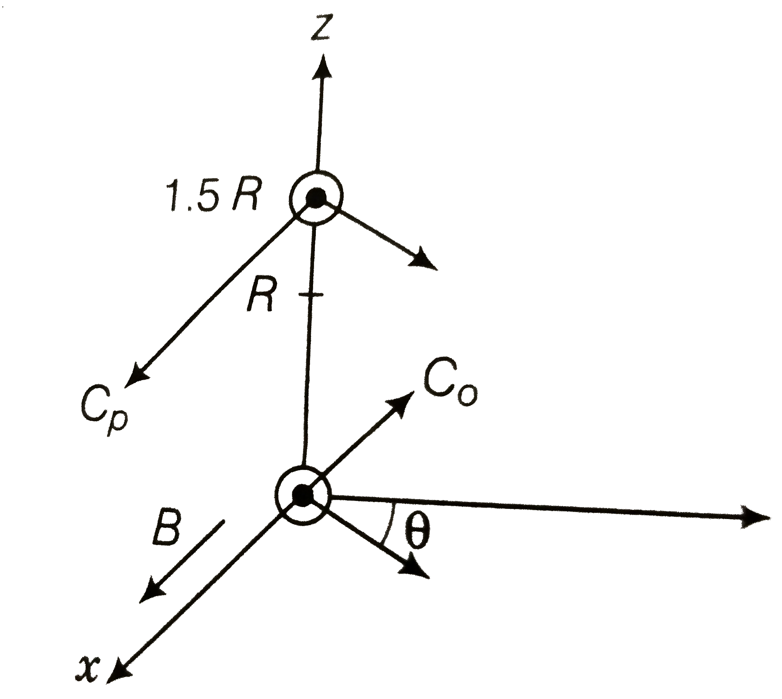
Since, B is along the x-axis, for a circular orbit the momenta of the two particle are in the y-z plane. Let ρ1andρ2 be the momentum of the electron and positron, respectively. Both traverse a circle of radius R of opposite sense. Let ρ1 make and angle θ with the y-axis ρ2 must make the same angle.
The centres of the respective circles must be perpendicular to the momenta and at a distance R. Let the centre of the electron be at Ce and of the positron at Cp. The coordinates of Cp is Cp≡(0,−Rsinθ,32R−Rcosθ)
the circles of the two shall not overlap if the distance between the two centers are greater than 2R.
Let d be the distance between CpandCe
Let d be the distance between CpandCe
Then, d2=(2Rsinθ)2+(32R−2Rcosθ)2
=4R2sin2θ+924R−6R2cosθ=4R2cos2θ ltBrgt =4R2+94R2−6R2cosθ
Since, d has to be greater than 2 R
d2>4R2
⇒4R2+94R2−6R2cosθ>4R2
⇒94>6cosθ
or, cosθ<38
POINT 4
Solenoid :
A long wire wound in the form of a helical coil is known as a solenoid.
Toroid :
If a solenoid is bent in a circular shape and the ends are joined, we get a toroid. Alternatively, one can start with a nonconducting ring and wind a conducting wire closely on it. The magnetic field in such a toroid can be obtained using Ampere's Law.
EXAMPLE 16
A uniform conducting wire of length 12a and resistance R is wound up as a current carrying coil in the shape of (i) an equilateral triangle of side a, (ii) a square of sides a and, (iii) a regular hexagon of sides a. the coil is connected to a voltage source V0 . Find the magnetic moment of the coils in each case.

We know that magnetic moment of the coils m=nlA.
Since, the same wire is used in three cases with same potential, therefore, same current flows in three cases.
(i) for an equilateral triangle of side a,
n=4 as the total wire of length =12a
Magnetic moment of the coils m=nIA=4I(√33a2)
∴m=Ia2√3.
(ii). For a square of sides a,
n=3 as the total wire of length=12a
Magnetic moment of the coils m=nIA=3I(a2)=3Ia2
(iii). For a regular hexagon of sides a,
n=2 as the total wire of length =12a
Magnetic moment of the coils m=nlA=21(6√34a2)
m=3√3a2I
m is a geometric series.
EXAMPLE 17
A solenoid of length 0.5 m has a radius of 1 cm and is made up of 500 turns. It carries a current of 5 A. What is the magnitude of the magnetic field inside the solenoid?
The number of turns per unit length is,
n=5000.5=1000turns/m
The length l=0.5m and radius r=0.01m.
Thus, la=50
i.e., l>>a
Hence, we can use the long solenoid formula, namely, Eq.
B=µ0nI
=4π×10–7×103×5
=6.28×10⁻³T
FORCE BETWEEN TWO PARALLEL CURRENTS, THE AMPERE
Do infinite length ki wire lete hai jisme se ek me current I1 and dusre me I2 hai. Yaha pr sirf current di hui hai magnetic field nahi diya hua hai. Hume force find karna hai wire 1 me wire 2 ke karan and wire 2 me wire 1 ke karan. Hume pata hai ki infinite long wire me force
F=I(→dl×→B)
hota hai. Ab wire 2 me force ho jayega
F2=I2(→dl×→B)
kyuki wire 2 me jo magnetic field hogi wo wire 1 ke karan hogi isliye force ki value ho jayegi.
F2=I2(dl×μ0I12πr)
F2=μ0I1I2dl2πr
F2dl=μ0I1I22πr
ye wire ke per unit length ke liye force hai.
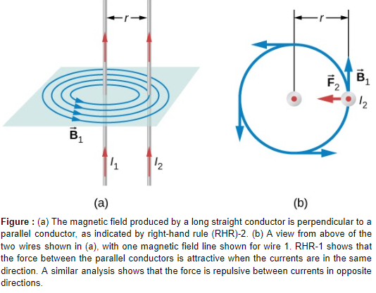
Force F2 ki direction uper figure me dikhai gayi hai. Ab wire 1 me force ho jayega
F1=I1(→dl×→B)
kyuki wire 1 me jo magnetic field hogi wo wire 2 ke karan hogi isliye force ki value ho jayegi.
F1=I1(dl×μ0I22πr)
F1=μ0I1I2dl2πr
F1dl=μ0I1I22πr
ye wire ke per unit length ke liye force hai.
- Ager dono wire me ek hi direction me current hai to wo ek dusre ko attract karenge opposite me hai to repel karenge.
- Parallel current attracts.
- Antiparallel current reple karte hai.
Jo force lg raha hai uska point of attraction center of wire me hoga.
OMR (One Minute Revision)
- * The field (B1) that that current (I1) from a wire creates can be calculated as a function of current and wire separation (r): B1=μ0I12πr, μ0 is a constant.
* F=IlBsinθ describes the magnetic force felt by a pair of wires. If they are parallel the equation is simplified as the sine function is 1.
* The force felt between two parallel conductive wires is used to define the ampere —the standard unit of current.
TORQUE ON CURRENT LOOP, MAGNETIC DIPOLE
Uniform magnetic field me current carrying conductor ka loop (Rectangular loop) rakha ho to current flow karane pr conductor rotate hone lagta hai. Jisse torque lagta hai.Torque on a rectangular current loop in a uniform magnetic field
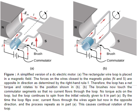
Magnetic field me charge move karne se charge pe force laga. Charge motion me hai means current hai to current carrying wire me bhi force lag raha hai. Ab ager rectangular current loop ko uniform magnetic field me rakh de to l length ke side wale wire me force hoga-
→F=i(→l×→B)=ilBsinθ
Kisi bhi band loop me uniform magnetic field me net force zero hoga. Current loop me jo sides magnetic field ki direction me hai unke wajah se force zero hojayega kyuki l aur B ke bich angle 0 hoga. Current loop me jo sides magnetic field ke perpendicular direction me hai unke wajah se same force lagenge but opposite direction me jise couple force kahte hai jo current loop ko ghuma dega jiski wajah se current loop me torque lagega. Kisi bhi rectangle loop ke liye net force zero hoga but torque zero nahi hoga.
Ab ager is loop ko uniform magnetic field me perpendicular na rakh kr kisi angle θ pe rakhe to aap figure me dekh sakte hai ki force ki direction kaise lagegi. F1 aur F3 ke liye line of section same hogi isliye inki wajah se force zero hoga aur torque τ1 aur τ3 bhi zero hoga jabki F2 aur F4 ek dusre ke equal aur opposite direction me hai jiski wajah loop ghumega aur torque τ2 and τ4 generate hoga. F2 me force bahar ki taraf (⋅) hai jabki F4 me force ander ki taraf (×) lag raha hai. Isliye center of loop me torque = magnitude of force × center of line ki force se perpendicular duri.
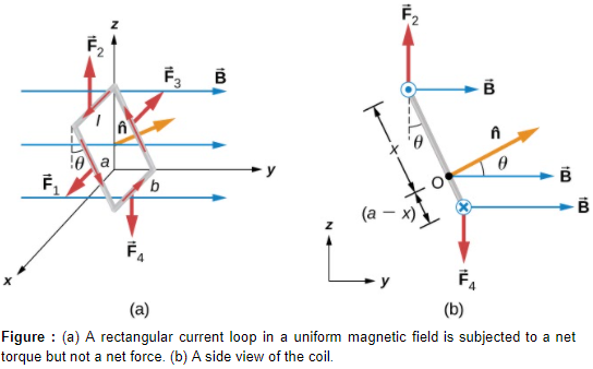
The point O is a distance x from side 2 and a distance (a−x) from side 4 of the loop. The moment arms of F2 and F4 are xsinθ and (a−x)sinθ, respectively, so the net torque on the loop is
∑→τ=→τ1+→τ2+→τ3+→τ4
=F2xsinθ−F4(a−x)sin(θ)
=(IbB)×(xsinθ)−(IbB)×((a−x)sinθ)
=I(ba)B×sinθ
This simplifies to
→τ=IABsinθ
where A=ab is the area of the loop.
→τ=mBsinθ
→τ=m×B
where m is magnetic dipole moment (m=IA)
For n number of turns magnetic dipole moment will be
m=nIA
The magnetic dipole moment of a revolving electron
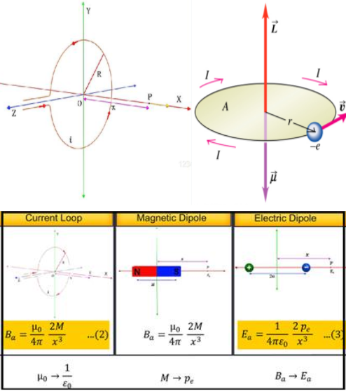
OMR (One Minute Revision)
- * τ=NIABsinθ can be used to calculate torque (τ) a loop of N turns and A area, carrying I current feels in the presence of a magnetic field B.
* Although the forces acting upon the loop are equal and opposite, they both act to rotate the loop in the same direction.
* Torque experienced is independent of the loop’s shape. What matters is the area of the loop.
EXAMPLE 18
The horizontal component of the earth’s magnetic field at a certain place is 3.0×10⁻⁵T and the direction of the field is from the geographic south to the geographic north. A very long straight conductor is carrying a steady current of 1A. What is the force per unit length on it when it is placed on a horizontal table and the direction of the current is (a) east to west; (b) south to north?
F=Il×B
F=IlBsinθ
The force per unit length is
f=Fl=IBsinθ
(a) When the current is flowing from east to west,
θ=90°
Hence,
f=IB
=1×3×10–5
=3×10⁻⁵Nm–1
This is larger than the value 2×10⁻⁷Nm–1 quoted in the definition of the ampere. Hence it is important to eliminate the effect of the earth’s magnetic field and other stray fields while standardising the ampere.
The direction of the force is downwards. This direction may be obtained by the directional property of the cross product of vectors.
(b) When the current is flowing from south to north,
θ=0∘
f=0
Hence there is no force on the conductor.
POINT 5
The Ampere :
One ampere of current through each of two parallel conductors of infinite length, separated by one meter in empty space free of other magnetic fields, causes a force of exactly 2×10⁻⁷ N/m on each conductor.
Torque :
A rotational or twisting effect of a force; (SI unit newton-meter or Nm)
Torque on a Current Loop :
Electrical energy from the current is converted to mechanical energy as the loop and shaft rotate, and this mechanical energy is then used to power another device.
Magnetic Moment :
The magnetic moment of a current loop can be defined as the product of the current flowing in the loop and the area of the rectangular loop.
EXAMPLE 19
A 100 turn closely wound circular coil of radius 10 cm carries a current of 3.2 A. (a) What is the field at the centre of the coil?
(b) What is the magnetic moment of this coil? The coil is placed in a vertical plane and is free to rotate about a horizontal axis which coincides with its diameter. A uniform magnetic field of 2T in the horizontal direction exists such that initially the axis of the coil is in the direction of the field. The coil rotates through an angle of 90º under the influence of the magnetic field.
(c) What are the magnitudes of the torques on the coil in the initial and final position?
(d) What is the angular speed acquired by the coil when it has rotated by 90º? The moment of inertia of the coil is 0.1kgm2 .
(a) From Eq.B=μ0NI2R
Here, N=100; I=3.2A, and R=0.1m
Hence,
B=4π×10−7×102×3.22×10−1
4×10−5×102×10−1
(using π×3.2=10)
=2×10⁻³T
The direction is given by the right-hand thumb rule.
(b) The magnetic moment is given by,
m=NIA
=NIπr2
=100×3.2×3.14×10–2
=10Am2
The direction is once again given by the right hand thumb rule.
(c) τ=m×B
=mBsinθ
Initially, θ=0.
Thus, initial torque τi=0
Finally, θ=π2 (or 90º). Thus, final torque
τf=mB=10×2=20Nm.
(d) From Newton’s second law,
Idωdt=mBsinθ
where I is the moment of inertia of the coil. From chain rule,
dωdt=dωdθdθdt=dωdθω
Using this,
Iωdω=mBsinθdθ
Integrating from θ=0→θ=π2,
I∫ωf0ωdω=mB∫π20sinθdθ
Iω2f2=−mB[cosθ]π20=mB
ωf=(2mBI)12
=(2×2010−1)½
=20s−1
EXAMPLE 17
(a) A current-carrying circular loop lies on a smooth horizontal plane. Can a uniform magnetic field be set up in such a manner that the loop turns around itself (i.e., turns about the vertical axis).
(b) A current-carrying circular loop is located in a uniform external magnetic field. If the loop is free to turn, what is its orientation of stable equilibrium? Show that in this orientation, the flux of the total field (external field + field produced by the loop) is maximum.
(c) A loop of irregular shape carrying current is located in an external magnetic field. If the wire is flexible, why does it change to a circular shape?
(a) No, because that would require τ to be in the vertical direction. But τ=IA×B,
and since A of the horizontal loop is in the vertical direction, τ would be in the plane of the loop for any B.
(b) Orientation of stable equilibrium is one where the area vector A of the loop is in the direction of the external magnetic field. In this orientation, the magnetic field produced by the loop is in the same direction as the external field, both normal to the plane of the loop, thus giving rise to maximum flux of the total field.
(c) It assumes a circular shape with its plane normal to the field to maximize flux, since for a given perimeter, a circle encloses a greater area than any other shape.
EXAMPLE 20
A uniform conducting wire of length 12a and resistance R is wound up as a current carrying coil in the shape of (i) an equilateral triangle of side a, (ii) a square of sides a and, (iii) a regular hexagon of sides a. the coil is connected to a voltage source V0 . Find the magnetic moment of the coils in each case.


We know that magnetic moment of the coils m=nlA.
Since, the same wire is used in three cases with same potential, therefore, same current flows in three cases.
(i) for an equilateral triangle of side a,
n=4 as the total wire of length =12a
Magnetic moment of the coils m=nIA=4I(√33a2)
∴m=Ia2√3.
(ii). For a square of sides a,
n=3 as the total wire of length=12a
Magnetic moment of the coils m=nIA=3I(a2)=3Ia2
(iii). For a regular hexagon of sides a,
n=2 as the total wire of length =12a
Magnetic moment of the coils m=nlA=21(6√34a2)
m=3√3a2I
m is a geometric series.
EXAMPLE 18
A multirange current meter can be constructed by using a galvanometer circuit as shown in figure. We want a current meter that can measure 10mA, 100mA and 1A using a galvanometer of resistance 10Ω and that produces maximum deflection for current of 1mA. Find S1,S2 and S3 that have to be used.
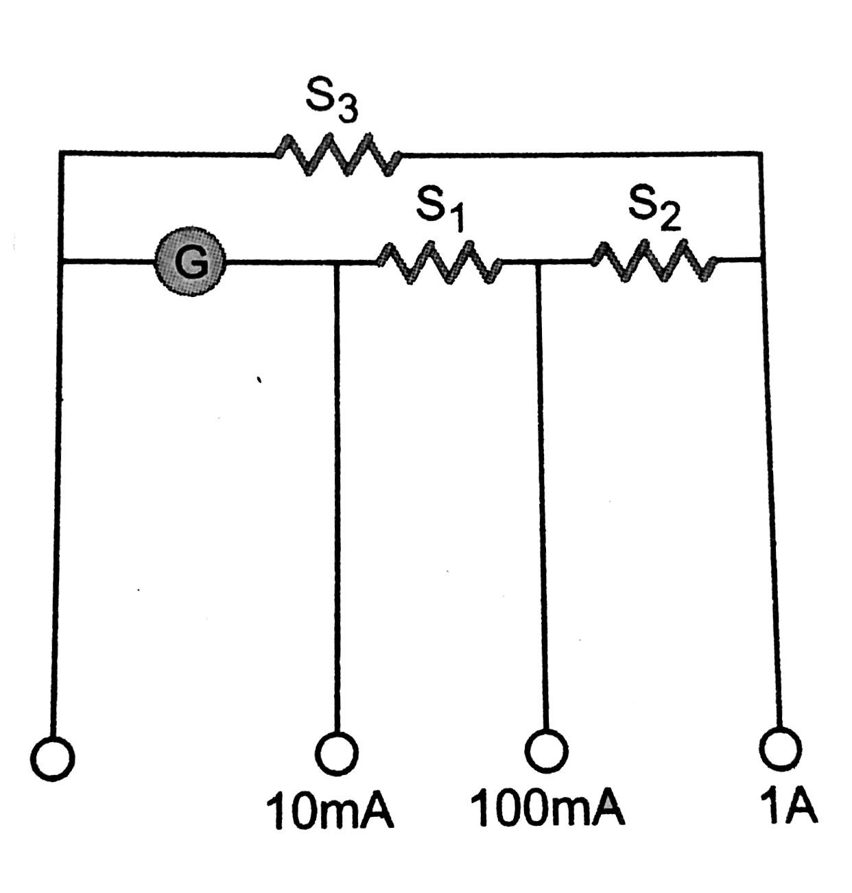
IG.G=(I1−IG)(S1+S2+S3) for I1=10mA
IG(G+S1)=(I2−IG)(S2+S3) for I2=100mA
and IG(G+S1+S2)=(I3−IG)(S3) for I3=1A
gives S1=1W,S2=0.1W
and S3=0.01W
FORCE BETWEEN TWO PARALLEL CURRENTS, THE AMPERE
Do infinite length ki wire lete hai jisme se ek me current I1 and dusre me I2 hai. Yaha pr sirf current di hui hai magnetic field nahi diya hua hai. Hume force find karna hai wire 1 me wire 2 ke karan and wire 2 me wire 1 ke karan. Hume pata hai ki infinite long wire me force
F=I(→dl×→B)
hota hai. Ab wire 2 me force ho jayega
F2=I2(→dl×→B)
kyuki wire 2 me jo magnetic field hogi wo wire 1 ke karan hogi isliye force ki value ho jayegi.
F2=I2(dl×μ0I12πr)
F2=μ0I1I2dl2πr
F2dl=μ0I1I22πr
ye wire ke per unit length ke liye force hai.

Force F2 ki direction uper figure me dikhai gayi hai. Ab wire 1 me force ho jayega
F1=I1(→dl×→B)
kyuki wire 1 me jo magnetic field hogi wo wire 2 ke karan hogi isliye force ki value ho jayegi.
F1=I1(dl×μ0I22πr)
F1=μ0I1I2dl2πr
F1dl=μ0I1I22πr
ye wire ke per unit length ke liye force hai.
- Ager dono wire me ek hi direction me current hai to wo ek dusre ko attract karenge opposite me hai to repel karenge.
- Parallel current attracts.
- Antiparallel current reple karte hai.
Jo force lg raha hai uska point of attraction center of wire me hoga.
OMR (One Minute Revision)
- * The field (B1) that that current (I1) from a wire creates can be calculated as a function of current and wire separation (r): B1=μ0I12πr, μ0 is a constant.
* F=IlBsinθ describes the magnetic force felt by a pair of wires. If they are parallel the equation is simplified as the sine function is 1.
* The force felt between two parallel conductive wires is used to define the ampere —the standard unit of current.
TORQUE ON CURRENT LOOP, MAGNETIC DIPOLE
Uniform magnetic field me current carrying conductor ka loop (Rectangular loop) rakha ho to current flow karane pr conductor rotate hone lagta hai. Jisse torque lagta hai.Torque on a rectangular current loop in a uniform magnetic field

Magnetic field me charge move karne se charge pe force laga. Charge motion me hai means current hai to current carrying wire me bhi force lag raha hai. Ab ager rectangular current loop ko uniform magnetic field me rakh de to l length ke side wale wire me force hoga-
→F=i(→l×→B)=ilBsinθ
Kisi bhi band loop me uniform magnetic field me net force zero hoga. Current loop me jo sides magnetic field ki direction me hai unke wajah se force zero hojayega kyuki l aur B ke bich angle 0 hoga. Current loop me jo sides magnetic field ke perpendicular direction me hai unke wajah se same force lagenge but opposite direction me jise couple force kahte hai jo current loop ko ghuma dega jiski wajah se current loop me torque lagega. Kisi bhi rectangle loop ke liye net force zero hoga but torque zero nahi hoga.
Ab ager is loop ko uniform magnetic field me perpendicular na rakh kr kisi angle θ pe rakhe to aap figure me dekh sakte hai ki force ki direction kaise lagegi. F1 aur F3 ke liye line of section same hogi isliye inki wajah se force zero hoga aur torque τ1 aur τ3 bhi zero hoga jabki F2 aur F4 ek dusre ke equal aur opposite direction me hai jiski wajah loop ghumega aur torque τ2 and τ4 generate hoga. F2 me force bahar ki taraf (⋅) hai jabki F4 me force ander ki taraf (×) lag raha hai. Isliye center of loop me torque = magnitude of force × center of line ki force se perpendicular duri.

The point O is a distance x from side 2 and a distance (a−x) from side 4 of the loop. The moment arms of F2 and F4 are xsinθ and (a−x)sinθ, respectively, so the net torque on the loop is
∑→τ=→τ1+→τ2+→τ3+→τ4
=F2xsinθ−F4(a−x)sin(θ)
=(IbB)×(xsinθ)−(IbB)×((a−x)sinθ)
=I(ba)B×sinθ
This simplifies to
→τ=IABsinθ
where A=ab is the area of the loop.
→τ=mBsinθ
→τ=m×B
where m is magnetic dipole moment (m=IA)
For n number of turns magnetic dipole moment will be
m=nIA
The magnetic dipole moment of a revolving electron

OMR (One Minute Revision)
- * τ=NIABsinθ can be used to calculate torque (τ) a loop of N turns and A area, carrying I current feels in the presence of a magnetic field B.
* Although the forces acting upon the loop are equal and opposite, they both act to rotate the loop in the same direction.
* Torque experienced is independent of the loop’s shape. What matters is the area of the loop.
EXAMPLE 19
Consider a circular current-carrying loop of radius R in the x-y plane with centre at origin. Consider the line integral ζ(L)=∣∣∣∫L−L→B.d→l∣∣∣ taken along z-axis.
(a) Show that ζ(L) monotonically increases with L.
(b) Use an appropriate Amperian loop to show that ζ(∞)=μ0I, where I is the current in the wire.
(c) Verify directly the above result.
(d) Suppose we replace the circular coil by a square coil of sides R carrying the same current I. What can you say about ζ(L) and ζ(∞)?

(a). B(z) points in the same direction on z-axis and hence , J(L) is a monotonically function of L. ltbtgt Since B and dl along the same direction, therefore B.dl=B.dl as cos0=1
(b). J(L)+contribution from large distance on contour C=μ0I
Contribution form large distance →0 (as B∝1/r3)
J(∞)−μ0I
(c). the magnetic field due to circular current-carrying loop of radius R in the x-y plane with centre at origin at any point lying at a distance of from origin.
BZ=μ0lR22(Z2+R2)3/2
∫∞−∞BZdz=∫∞−∞μ0lR22(Z2+R2)3/2dz
Put Z=Rtanθ1
⇒dZ=Rsec2θdθ
∴∫∞−∞Bzdz=μ0I2∫π/2−π/2cosθdθ=μ0I
(d). B(Z)square<B(Z)circular coil
∑(L)square<∑(L)circular coil
but by using arguments as in (b)
∑(∞)square=sun(∞)circular
POINT 5
The Ampere :
One ampere of current through each of two parallel conductors of infinite length, separated by one meter in empty space free of other magnetic fields, causes a force of exactly 2×10⁻⁷ N/m on each conductor.
Torque :
A rotational or twisting effect of a force; (SI unit newton-meter or Nm)
Torque on a Current Loop :
Electrical energy from the current is converted to mechanical energy as the loop and shaft rotate, and this mechanical energy is then used to power another device.
Magnetic Moment :
The magnetic moment of a current loop can be defined as the product of the current flowing in the loop and the area of the rectangular loop.
THE MOVING COIL GALVANOMETER
Moving coil galvanometer is a device used for measuring the current in a circuit. Galvanometer pata lagata hai ki circuit me current hai ya nahi aur hai to kitna hai. Dhyan rakhiye ki electric current ki value km honi chahiye kyuki value jyada hogi to galvanometer jal jayega. Isiliye big currents ke measurement ke liye hume ammeter banane ki jarurat padhi.
A galvanometer is a device used for the detection and measurement of small electric currents.
Principle - A current carrying coil placed in a magnetic field experiences a current dependent torque, which tends to rotate the coil and produces angular deflection.
Jab current carrying coil ko magnetic field me rakhte hai to coil current dependent torque feel karta hai mtlb current badhange to torque jyada badh jayega aur wahi chij humari angular deflection ko dikhati hai. Ager formula base pe samjhe to-
α=NBAkl
Yaha α kitna coil rotate kiya hai. Isi pe needle laga ke coil rakhe the to isi pe jab magnetic field lag de to kitna rotate kiya hai ye yaha se nikali ja ry hai.
k= spring constant ya torsion constant
N number of turns ki usme wire kitna lapete hue hai.
B hai magnetic field
A area of aperture
ye sari value constant hai. Isiliye α∝I
current jyada to α bhi jyada means jyada current flow kiya to jyada ghum gaya.
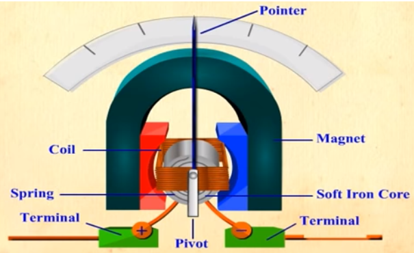
Figure of merit of galvanometer
G=Iα=kNBA
Current sensitivity
It is defined as the deflection produced in the galvanometer when a unit current flows through it.Jo deflection ho raha tha wo per unit current pe kitna hoga yahi current sensitivity hai. Chhoti se current galvanometer pe ager bheji jaye to pointer deflect ho to ry hai to pointer current sensitive hai. Bht hi small amount ke current ke liye bhi jab achcha deflection mile to wo highly current sensitive hai.
IS=αI=NBAk
IS= current sensitivity
Voltage sensitivity
It is defined as the deflection produced in the galvanometer when a unit potential difference is applied across its ends.VS=αV=αIR=NBAkR
VS=ISR
Per unit voltage ke liye jitna deflection ho.
Factors affects the sensitivity -
Galvanometer ki sensitivity following factors pe depend kr ry hai-
1. N= number of turns N in its coil.
2. Magnetic field B.
3. Area A of the coil.
4. Torsion constant k of the spring and suspension wire.
Conversion of Galvanometer into an ammeter
Galvanometer ko ammeter me badalne ke liye shunt bht jaruri hai. Shunt ek low resistance hota hai jo galvanometer ya ammeter se parallel me connect rahta hai. Ye shunt resistance ammeter ko strong current se protect karta hai. Is tarah shunt resistance ko galvanometer ke parallel me connect karne se galvanometer ammeter me change ho jata hai. Niche diye gaye figure me aap dekh sakte hai ki galvanometer ke parallel me S shunt resistance hai aur G galvanometer ka internal resistance hai. Jab jyada current galvanometer se flow karate hai to galvanometer jhel hi ny pata wo burn ho jata kyuki galvanometer bht sensitive hota hai lekin jb parallel me low resistance S connect kr de to S ka resistance km hone ke karan large current ka maximum hissa low resistance se flow ho jata hai isliye galvanometer se bht hi small amount ka current (Ig) flow hota hai aur galvanometer damage hone se bach jata hai.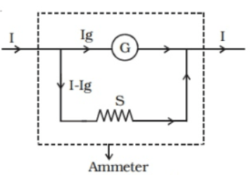
Galvanometer resistance = G
Shunt resistance = S
Current in the circuit = I
∴ Current through the shunt resistance =Is=(I−Ig)
Since the galvanometer and shunt resistance are parallel, isiliye dono ke liye voltage same hoga to hum likh sakte hai.
∴ =IgG=(I−Ig)S
S=GIgI−Ig
The shunt resistance is very small because Ig is only a fraction of I.
Ammeter ek shunted or low resistance galvanometer hai isiliye effective resistance of the ammeter Ra is (G in parallel with S)
1Ra=1G+1S
∴Ra=GSG+S
Parallel me low resistance laga dene se equivalent resistance aur bhi km ho gaya.
Galvanometer ko humne iske parallel me shunt resistance connect karke ammeter me convert kiya.
Uses of Shunt
* Galvanometer ko large current se prevent karta hai.* Galvanometer to ammeter me convert karta hai.
* Shunt resistance ka use karke hum ammeter ki range badha skte hai mtlb large value of current ko bhi measure kr sakte hai.
Conversion of Galvanometer into a voltmeter
A galvanometer is converted to voltmeter by putting high resistance in series with it.Niche diye figure me aap dekhoge to R resistance high value ka resistance hume galvanometer ke series me connect kiya hai. High resistance series me connect hone ke karan Ig current bht km jayegi.
Ab dhyan dene wali baat ye hai ki aap class 10th me padhe hai ki kisi volmeter ko kisi do point ke bich ka voltage measure karne ke liye dono point ke across parallel me connect karte hai kyuki volmeter ke series me high resistance hone ke karan volmeter se current Ig bht hi small amount ka current jata hai jisse voltmeter dono points ke bich ke voltage ko accurately measure karta hai.
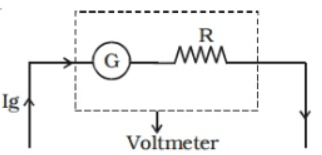
Galvanometer resistance = G
The current required to produce full scale deflection in the galvanometer =Ig
Range of voltmeter =V
Resistance to be connected in series =R
Since R is connected in series with the galvanometer, the current through the galvanometer,
Ig=VR+G
∴ R=VIg−G
From the equation the resistance to be connected in series with the galvanometer is calculated.
The effective resistance of the voltmeter is
Rv=G+R>>G
Voltmeter ek high resistance galvanometer hai isiliye effective resistance galvanometer resistance se bhi greater hoga.
- Galvanometer ke parallel me high resistance ko connect karne galvanometer ko voltmeter me convert karte hai.
Jab hume current measure karna tha to humne low resistance ko galvanometer ke parallel me connect karte hai jab voltage measure karna ho to resistance ki high value ko galvanometer ke series me connect karte hai
OMR (One Minute Revision)
- * Galvanometer is a sensitive electromagnetic device which can measure low currents even of the order of a few microamperes.
* The galvanometer shows deflection in the opposite direction indicating that the direction of the induced current is reversed.
* The MI instrument is independent of the direction of current and hence used for both AC and DC.
EXAMPLE 21
(a) A current-carrying circular loop lies on a smooth horizontal plane. Can a uniform magnetic field be set up in such a manner that the loop turns around itself (i.e., turns about the vertical axis).
(b) A current-carrying circular loop is located in a uniform external magnetic field. If the loop is free to turn, what is its orientation of stable equilibrium? Show that in this orientation, the flux of the total field (external field + field produced by the loop) is maximum.
(c) A loop of irregular shape carrying current is located in an external magnetic field. If the wire is flexible, why does it change to a circular shape?
(a) No, because that would require τ to be in the vertical direction. But τ=IA×B,
and since A of the horizontal loop is in the vertical direction, τ would be in the plane of the loop for any B.
(b) Orientation of stable equilibrium is one where the area vector A of the loop is in the direction of the external magnetic field. In this orientation, the magnetic field produced by the loop is in the same direction as the external field, both normal to the plane of the loop, thus giving rise to maximum flux of the total field.
(c) It assumes a circular shape with its plane normal to the field to maximize flux, since for a given perimeter, a circle encloses a greater area than any other shape.
POINT 6
Galvanometer :
A galvanometer is a device used for the detection and measurement of small electric currents.
Current sensitivity :
It is defined as the deflection produced in the galvanometer when a unit current flows through it.
Voltage sensitivity :
It is defined as the deflection produced in the galvanometer when a unit potential difference is applied across its ends.
Ammeter :
A galvanometer is converted to ammeter by putting low resistance (shunt) in parallel with it.
Shunt Resistance :
Shunt is a low resistance connected in parallel with the galvanometer for ammeter to protect it from strong currents.
Voltmeter :
A galvanometer is converted to voltmeter by putting high resistance in series with it.
EXAMPLE 22
A rectangular conducting loop consists of two wires on two opposite sides of length l joined together by rods of length d. The wires are each of the same material but with cross-sections differing by a factor of 2. the thicker wire has a resistance R and the rods are of low resistance, which in turn are connected to a constant voltage source V0. The loop is placed in uniform magnetic field B at 45∘ to its plane. find τ, the torque exerted by the magnetic field on the loop about and axis through the centres of rods.

Thicker wire has a resistance R, then the other wire has a resistance 2R as the wires are of the same material but with cross-sections differing by a factor 2.
Now, the force and hence, torque on first wire is given by
F1=i1iB=V02RlB,τ1=d2√2F1=V0ldB2√2R
Similarly, the force hence torque on other wire is given by
F2=i2lB=V02RlB,τ2=d2√2F2=V0ldB4√2R
So, net torque τ=τ1−τ2
τ=14√2V0ldBR
EXAMPLE 20
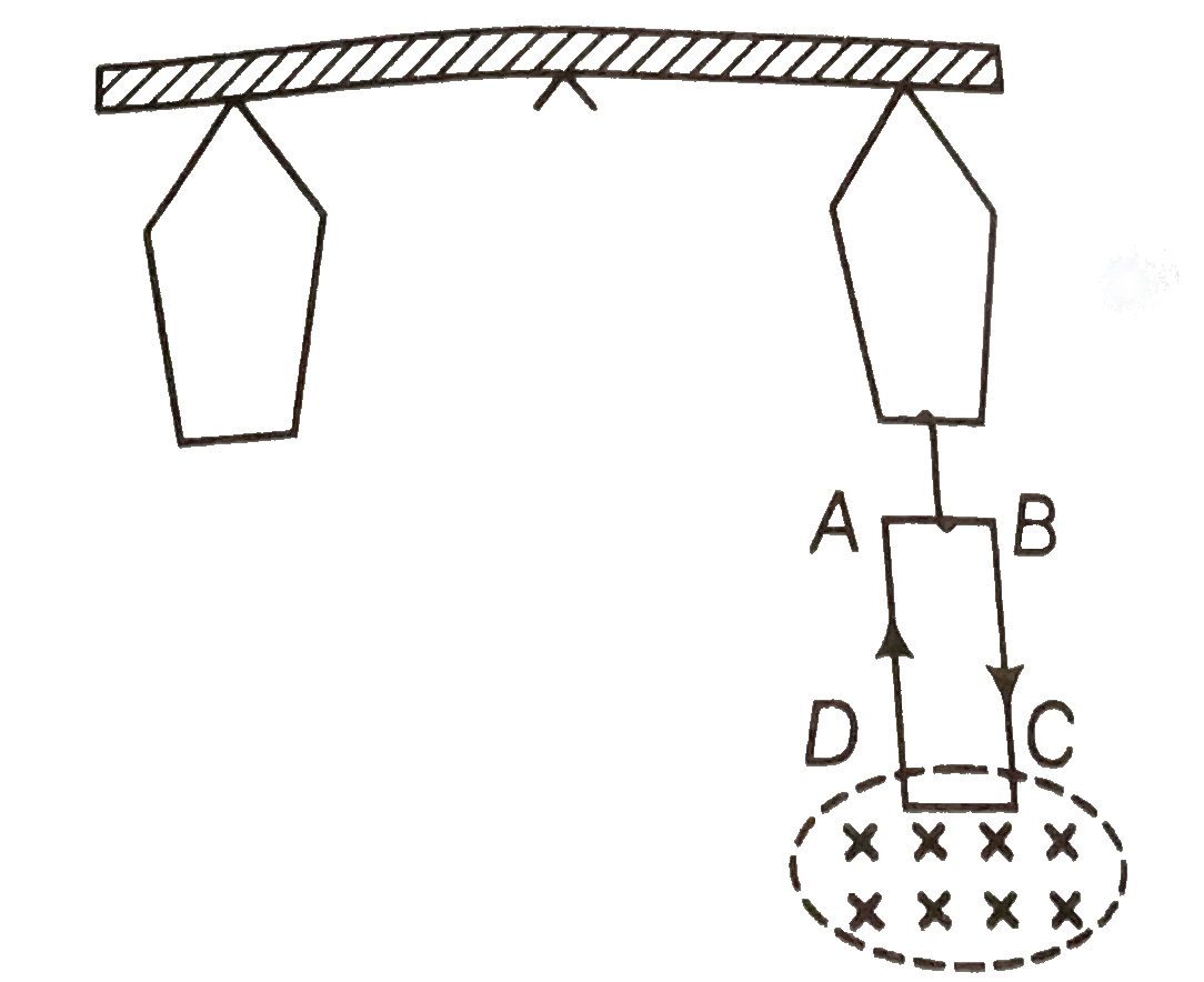
A 100 turn ractangular coil ABCD (in X-Y plane) is hung from one arm of a balance figure. A mass 500 g is added to the other arm to balance the weight of the coil. A current 4.9 A passed through the coil and a constant magnetic field of 0.2 T acting inward (in x-z plane) is switched on such that only arm Cd of length 1 cm lies in the field. How much additional mass m must be added to regain the balance?
For equilibrium/balance, net torque should also be equal to zero
When the field is off ∑t=0 considering the separation of each hung from mid-point be l
Mgl=Wcoill
500gl=Wcoill
Wcoil=500×9.8N
Taking moment of force about mid-point, we have the weight of coil
When the magnetic field is switched on
Mgl+mgl=Wcoill+IBLsin90∘I
mgl=BILl
m=BILg=0.2×4.9×1×10−29.8=10−3kg=1g
Thus, 1 g of additional mass must be added to regain the balance.
EXAMPLE 23
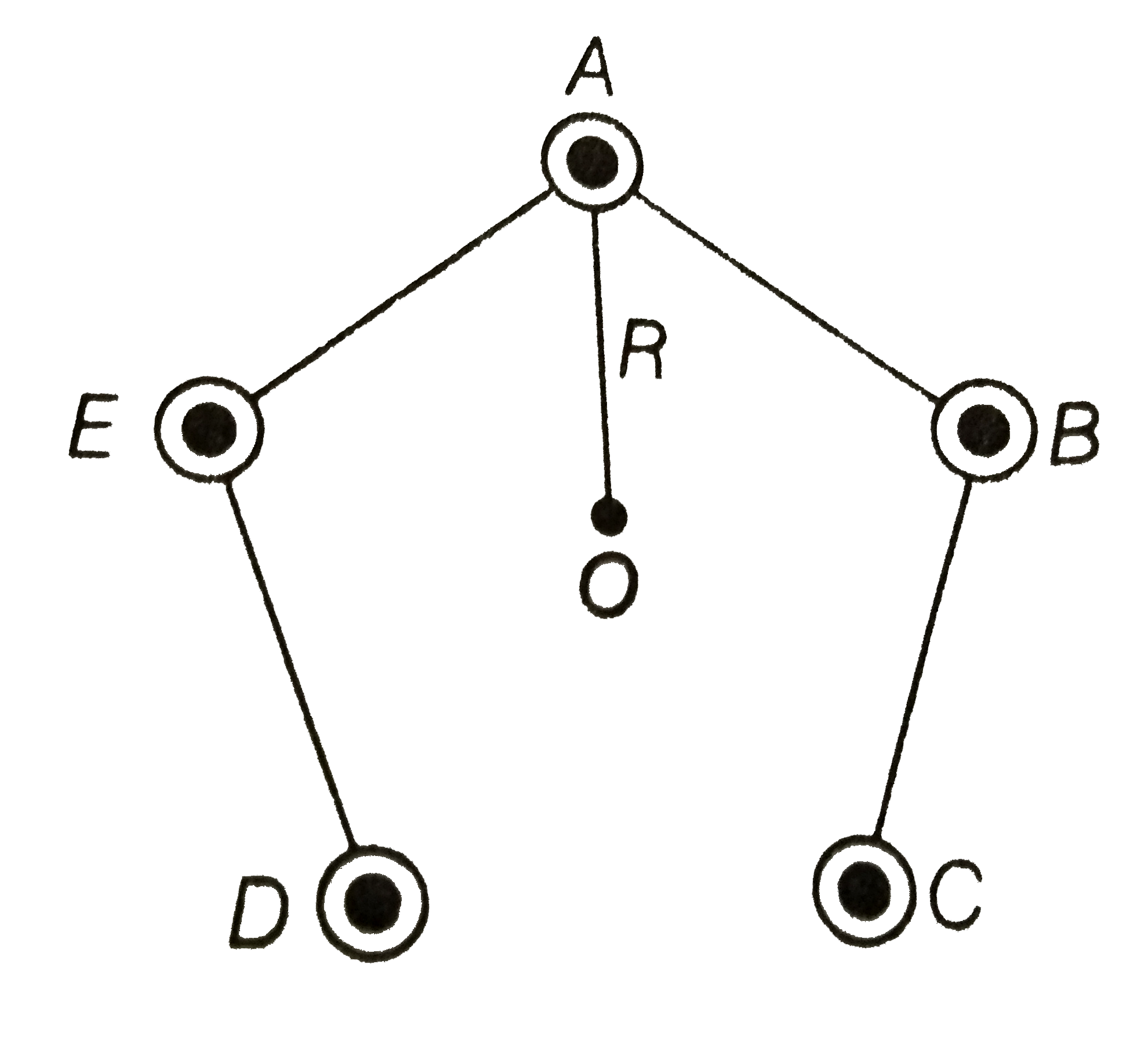
Five long wires A,B,C,D and E, each carrying current I are arranged to form edges of a pentagonal prism as shown in figure. Each carries current out of the plane of paper.
(a). What will be magnetic induction at a point on the axis 0? Axis is at a distance R from each wire.
(b). What will be the field if current in one of the wires (say A) is switched off?
(c). What if current in one of the wire (say A) is reversed?
(a). Suppose the five wires A, B,C, D and E be perpendicular to the plane of paper at locations as shown in figure.
Thus, magnetic field induction due to five wires will be represented by various sides of a closed pentagon in one order, lying in the plane of paper. So, its value is zero.
(b). Since, the vector sum of magnetic field produced by each wire at O is equal to 0. Therefore, magnetic induction produced by one current carrying wire is equal in magnitude of resultant of four wires and opposite in direction.
Therefore, the field if current in one of the wires (say A) is switched off is μ02πiR
perpendicular to AO towards left.
(c). if current in wire A is reversed, then
total magnetic field induction at O .
=Magnetic field induction due to wire A+ magnetic field induction due to wires B,C,D and E
=μ04πR2IR
(acting perpendicular to AO towards left) +μ0π2πR (acting perpendicular AO towards left)
=μ0IπR acting perpendicular AO towards left.
EXAMPLE 21
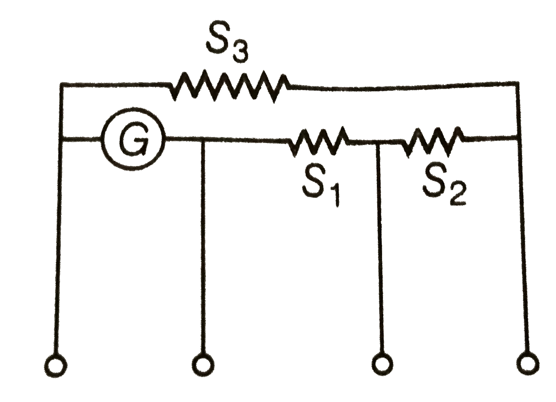
A multirange current meter can be constructed by using a galvanometer circuit as shown in figure. We want a current meter that can measure 10 mA, 100 mA and 1mA using a galvanometer of resistance 10Ω and that produces maximum deflection for current of 1mA. find S1,S2andS3 that have to be used.
IG.G=(I1−IG)(S1+S2+S3) for I1=10mA
IG(G+S1)=(I2−IG)(S2+S3) for I2=100mA
and IG(G+S1+S2)=(I3−IG)(S3) for I3=1A
gives S1=1W,S2=0.1W
and S3=0.01W
THE MOVING COIL GALVANOMETER
Moving coil galvanometer is a device used for measuring the current in a circuit. Galvanometer pata lagata hai ki circuit me current hai ya nahi aur hai to kitna hai. Dhyan rakhiye ki electric current ki value km honi chahiye kyuki value jyada hogi to galvanometer jal jayega. Isiliye big currents ke measurement ke liye hume ammeter banane ki jarurat padhi.
A galvanometer is a device used for the detection and measurement of small electric currents.
Principle - A current carrying coil placed in a magnetic field experiences a current dependent torque, which tends to rotate the coil and produces angular deflection.
Jab current carrying coil ko magnetic field me rakhte hai to coil current dependent torque feel karta hai mtlb current badhange to torque jyada badh jayega aur wahi chij humari angular deflection ko dikhati hai. Ager formula base pe samjhe to-
α=NBAkl
Yaha α kitna coil rotate kiya hai. Isi pe needle laga ke coil rakhe the to isi pe jab magnetic field lag de to kitna rotate kiya hai ye yaha se nikali ja ry hai.
k= spring constant ya torsion constant
N number of turns ki usme wire kitna lapete hue hai.
B hai magnetic field
A area of aperture
ye sari value constant hai. Isiliye α∝I
current jyada to α bhi jyada means jyada current flow kiya to jyada ghum gaya.

Figure of merit of galvanometer
G=Iα=kNBA
Current sensitivity
It is defined as the deflection produced in the galvanometer when a unit current flows through it.Jo deflection ho raha tha wo per unit current pe kitna hoga yahi current sensitivity hai. Chhoti se current galvanometer pe ager bheji jaye to pointer deflect ho to ry hai to pointer current sensitive hai. Bht hi small amount ke current ke liye bhi jab achcha deflection mile to wo highly current sensitive hai.
IS=αI=NBAk
IS= current sensitivity
Voltage sensitivity
It is defined as the deflection produced in the galvanometer when a unit potential difference is applied across its ends.VS=αV=αIR=NBAkR
VS=ISR
Per unit voltage ke liye jitna deflection ho.
Factors affects the sensitivity -
Galvanometer ki sensitivity following factors pe depend kr ry hai-
1. N= number of turns N in its coil.
2. Magnetic field B.
3. Area A of the coil.
4. Torsion constant k of the spring and suspension wire.
Conversion of Galvanometer into an ammeter
Galvanometer ko ammeter me badalne ke liye shunt bht jaruri hai. Shunt ek low resistance hota hai jo galvanometer ya ammeter se parallel me connect rahta hai. Ye shunt resistance ammeter ko strong current se protect karta hai. Is tarah shunt resistance ko galvanometer ke parallel me connect karne se galvanometer ammeter me change ho jata hai. Niche diye gaye figure me aap dekh sakte hai ki galvanometer ke parallel me S shunt resistance hai aur G galvanometer ka internal resistance hai. Jab jyada current galvanometer se flow karate hai to galvanometer jhel hi ny pata wo burn ho jata kyuki galvanometer bht sensitive hota hai lekin jb parallel me low resistance S connect kr de to S ka resistance km hone ke karan large current ka maximum hissa low resistance se flow ho jata hai isliye galvanometer se bht hi small amount ka current (Ig) flow hota hai aur galvanometer damage hone se bach jata hai.
Galvanometer resistance = G
Shunt resistance = S
Current in the circuit = I
∴ Current through the shunt resistance =Is=(I−Ig)
Since the galvanometer and shunt resistance are parallel, isiliye dono ke liye voltage same hoga to hum likh sakte hai.
∴ =IgG=(I−Ig)S
S=GIgI−Ig
The shunt resistance is very small because Ig is only a fraction of I.
Ammeter ek shunted or low resistance galvanometer hai isiliye effective resistance of the ammeter Ra is (G in parallel with S)
1Ra=1G+1S
∴Ra=GSG+S
Parallel me low resistance laga dene se equivalent resistance aur bhi km ho gaya.
Galvanometer ko humne iske parallel me shunt resistance connect karke ammeter me convert kiya.
Uses of Shunt
* Galvanometer ko large current se prevent karta hai.* Galvanometer to ammeter me convert karta hai.
* Shunt resistance ka use karke hum ammeter ki range badha skte hai mtlb large value of current ko bhi measure kr sakte hai.
Conversion of Galvanometer into a voltmeter
A galvanometer is converted to voltmeter by putting high resistance in series with it.Niche diye figure me aap dekhoge to R resistance high value ka resistance hume galvanometer ke series me connect kiya hai. High resistance series me connect hone ke karan Ig current bht km jayegi.
Ab dhyan dene wali baat ye hai ki aap class 10th me padhe hai ki kisi volmeter ko kisi do point ke bich ka voltage measure karne ke liye dono point ke across parallel me connect karte hai kyuki volmeter ke series me high resistance hone ke karan volmeter se current Ig bht hi small amount ka current jata hai jisse voltmeter dono points ke bich ke voltage ko accurately measure karta hai.

Galvanometer resistance = G
The current required to produce full scale deflection in the galvanometer =Ig
Range of voltmeter =V
Resistance to be connected in series =R
Since R is connected in series with the galvanometer, the current through the galvanometer,
Ig=VR+G
∴ R=VIg−G
From the equation the resistance to be connected in series with the galvanometer is calculated.
The effective resistance of the voltmeter is
Rv=G+R>>G
Voltmeter ek high resistance galvanometer hai isiliye effective resistance galvanometer resistance se bhi greater hoga.
- Galvanometer ke parallel me high resistance ko connect karne galvanometer ko voltmeter me convert karte hai.
Jab hume current measure karna tha to humne low resistance ko galvanometer ke parallel me connect karte hai jab voltage measure karna ho to resistance ki high value ko galvanometer ke series me connect karte hai
OMR (One Minute Revision)
- * Galvanometer is a sensitive electromagnetic device which can measure low currents even of the order of a few microamperes.
* The galvanometer shows deflection in the opposite direction indicating that the direction of the induced current is reversed.
* The MI instrument is independent of the direction of current and hence used for both AC and DC.
SUMMARY
1. The total force on a charge q moving with velocity v in the presence of magnetic and electric fields B and E, respectively is called the Lorentz force. It is given by the expression:
F=q(v×B+E)
The magnetic force q(v×B) is normal to v and work done by it is zero.
2. A straight conductor of length l and carrying a steady current I experiences a force F in a uniform external magnetic field B,
F=Il×B
where |l|=l and the direction of l is given by the direction of the current.
3. In a uniform magnetic field B, a charge q executes a circular orbit in a plane normal to B. Its frequency of uniform circular motion is called the cyclotron frequency and is given by:
vc=qB2πm
This frequency is independent of the particle’s speed and radius. This fact is exploited in a machine, the cyclotron, which is used to accelerate charged particles.
4. The Biot-Savart law asserts that the magnetic field dB due to an element dl carrying a steady current I at a point P at a distance r from the current element is:
dB=μ04πIdl×rr3
To obtain the total field at P, we must integrate this vector expression over the entire length of the conductor.
5. The magnitude of the magnetic field due to a circular coil of radius R carrying a current I at an axial distance x from the centre is
B=μ0IR22(x2+R2)32
At the center this reduces to
B=µ0I2R
6. Ampere’s Circuital Law: Let an open surface S be bounded by a loop C. Then the Ampere’s law states that ∮CB.dl=μ0I where I refers to the current passing through S. The sign of I is determined from the right-hand rule. We have discussed a simplified form of this law. If B is directed along the tangent to every point on the perimeter L of a closed curve and is constant in magnitude along perimeter then, BL=µ0Ie where Ie is the net current enclosed by the closed circuit.
7. The magnitude of the magnetic field at a distance R from a long, straight wire carrying a current I is given by:
B=µ0I2πR
The field lines are circles concentric with the wire.
8. The magnitude of the field B inside a long solenoid carrying a current I is
B=µ0nI
where n is the number of turns per unit length. For a toroid one obtains,
B=µNI2πr
where N is the total number of turns and r is the average radius.
9. Parallel currents attract and anti-parallel currents repel.
10. A planar loop carrying a current I, having N closely wound turns, and an area A possesses a magnetic moment m where,
m=NIA
and the direction of m is given by the right-hand thumb rule : curl the palm of your right hand along the loop with the fingers pointing in the direction of the current. The thumb sticking out gives the direction of m (and A)
When this loop is placed in a uniform magnetic field B, the force F on it is: F=0
And the torque on it is,
τ=m×B
In a moving coil galvanometer, this torque is balanced by a counter torque due to a spring, yielding
kφ=NIAB
where φ is the equilibrium deflection and k the torsion constant of the spring.
11. An electron moving around the central nucleus has a magnetic moment µl given by:
µl=e2ml
where l is the magnitude of the angular momentum of the circulating electron about the central nucleus. The smallest value of µl is called the Bohr magneton µB and it is
µB=9.27×10⁻²⁴J/T
12. A moving coil galvanometer can be converted into an ammeter by introducing a shunt resistance rs, of small value in parallel. It can be converted into a voltmeter by introducing a resistance of a large value in series.
13. Electrostatic field lines originate at a positive charge and terminate at a negative charge or fade at infinity. Magnetic field lines always form closed loops.
14. The discussion in this Chapter holds only for steady currents which do not vary with time. When currents vary with time Newton’s third law is valid only if momentum carried by the electromagnetic field is taken into account.
15. Recall the expression for the Lorentz force,
F=q(v×B+E)
This velocity dependent force has occupied the attention of some of the greatest scientific thinkers. If one switches to a frame with instantaneous velocity v, the magnetic part of the force vanishes. The motion of the charged particle is then explained by arguing that there exists an appropriate electric field in the new frame. We shall not discuss the details of this mechanism. However, we stress that the resolution of this paradox implies that electricity and magnetism are linked phenomena (electromagnetism) and that the Lorentz force expression does not imply a universal preferred frame of reference in nature.
16. Ampere’s Circuital law is not independent of the Biot-Savart law. It can be derived from the Biot-Savart law. Its relationship to the Biot-Savart law is similar to the relationship between Gauss’s law and Coulomb’s law.
POINT 6
Galvanometer :
A galvanometer is a device used for the detection and measurement of small electric currents.
Current sensitivity :
It is defined as the deflection produced in the galvanometer when a unit current flows through it.
Voltage sensitivity :
It is defined as the deflection produced in the galvanometer when a unit potential difference is applied across its ends.
Ammeter :
A galvanometer is converted to ammeter by putting low resistance (shunt) in parallel with it.
Shunt Resistance :
Shunt is a low resistance connected in parallel with the galvanometer for ammeter to protect it from strong currents.
Voltmeter :
A galvanometer is converted to voltmeter by putting high resistance in series with it.
EXAMPLE 24
In the circuit (Fig.) the current is to be measured. What is the value of the current if the ammeter shown (a) is a galvanometer with a resistance RG=60.00Ω; (b) is a galvanometer described in (a) but converted to an ammeter by a shunt resistance rs=0.02Ω; (c) is an ideal ammeter with zero resistance?
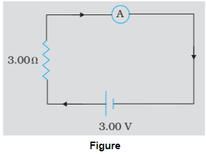
(a) Total resistance in the circuit is,
RG+3=63Ω
Hence, I=363=0.048A
(b) Resistance of the galvanometer converted to an ammeter is,
RGrsRG+rs=60×0.0260+0.02Ω=0.02Ω
Total resistance in the circuit is,
0.02+3=3.02Ω
Hence, I=33.02=0.99A
(c) For the ideal ammeter with zero resistance,
I=33=1.00A
EXAMPLE 25
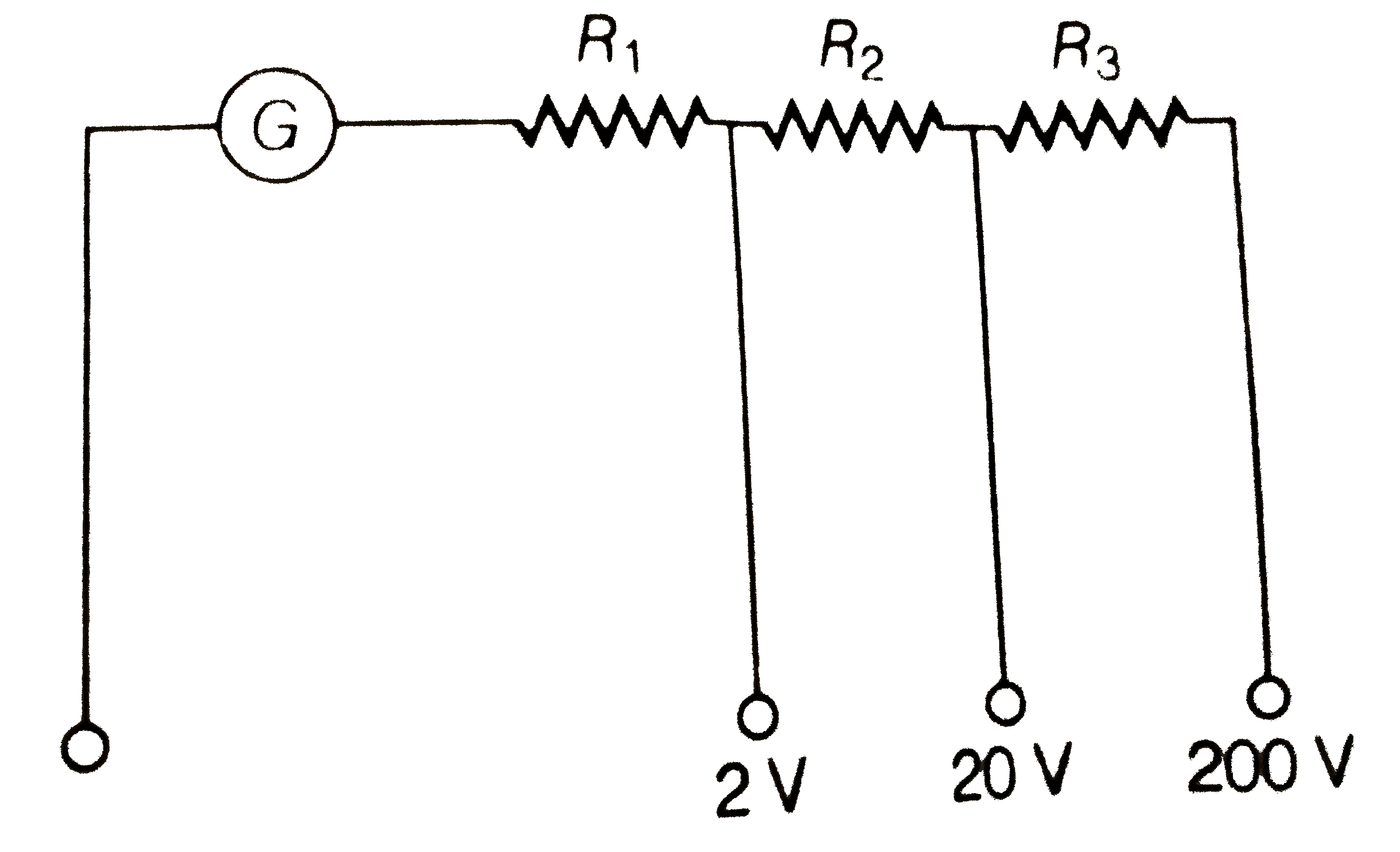
A multirange voltmeter can be constructed by using a galvanometer circuit as shown in figure. We want to construct a voltmeter that can measure 2V, 20V and 200V using a galvanometer of resistance 10Ω and that produces maximum deflection for current of 1 mA. Find R1,R2andR3 that have to be used.
 .
.
Applying expression in different situations ltbr For iG(G+R1)=2 For 2V range
For IG(G+R1+R2)=2 For 20V range ltbr> And for IG(G+R1+R2+R3)=200 For 200V range
On solving we get R1=1990Ω,R2=18kΩandR3=180kΩ
EXAMPLE 26

A 100 turn ractangular coil ABCD (in X-Y plane) is hung from one arm of a balance figure. A mass 500 g is added to the other arm to balance the weight of the coil. A current 4.9 A passed through the coil and a constant magnetic field of 0.2 T acting inward (in x-z plane) is switched on such that only arm Cd of length 1 cm lies in the field. How much additional mass m must be added to regain the balance?
For equilibrium/balance, net torque should also be equal to zero
When the field is off ∑t=0 considering the separation of each hung from mid-point be l
Mgl=Wcoill
500gl=Wcoill
Wcoil=500×9.8N
Taking moment of force about mid-point, we have the weight of coil
When the magnetic field is switched on
Mgl+mgl=Wcoill+IBLsin90∘I
mgl=BILl
m=BILg=0.2×4.9×1×10−29.8=10−3kg=1g
Thus, 1 g of additional mass must be added to regain the balance.
EXAMPLE 27

A multirange current meter can be constructed by using a galvanometer circuit as shown in figure. We want a current meter that can measure 10 mA, 100 mA and 1mA using a galvanometer of resistance 10Ω and that produces maximum deflection for current of 1mA. find S1,S2andS3 that have to be used.
IG.G=(I1−IG)(S1+S2+S3) for I1=10mA
IG(G+S1)=(I2−IG)(S2+S3) for I2=100mA
and IG(G+S1+S2)=(I3−IG)(S3) for I3=1A
gives S1=1W,S2=0.1W
and S3=0.01W
SUMMARY
1. The total force on a charge q moving with velocity v in the presence of magnetic and electric fields B and E, respectively is called the Lorentz force. It is given by the expression:
F=q(v×B+E)
The magnetic force q(v×B) is normal to v and work done by it is zero.
2. A straight conductor of length l and carrying a steady current I experiences a force F in a uniform external magnetic field B,
F=Il×B
where |l|=l and the direction of l is given by the direction of the current.
3. In a uniform magnetic field B, a charge q executes a circular orbit in a plane normal to B. Its frequency of uniform circular motion is called the cyclotron frequency and is given by:
vc=qB2πm
This frequency is independent of the particle’s speed and radius. This fact is exploited in a machine, the cyclotron, which is used to accelerate charged particles.
4. The Biot-Savart law asserts that the magnetic field dB due to an element dl carrying a steady current I at a point P at a distance r from the current element is:
dB=μ04πIdl×rr3
To obtain the total field at P, we must integrate this vector expression over the entire length of the conductor.
5. The magnitude of the magnetic field due to a circular coil of radius R carrying a current I at an axial distance x from the centre is
B=μ0IR22(x2+R2)32
At the center this reduces to
B=µ0I2R
6. Ampere’s Circuital Law: Let an open surface S be bounded by a loop C. Then the Ampere’s law states that ∮CB.dl=μ0I where I refers to the current passing through S. The sign of I is determined from the right-hand rule. We have discussed a simplified form of this law. If B is directed along the tangent to every point on the perimeter L of a closed curve and is constant in magnitude along perimeter then, BL=µ0Ie where Ie is the net current enclosed by the closed circuit.
7. The magnitude of the magnetic field at a distance R from a long, straight wire carrying a current I is given by:
B=µ0I2πR
The field lines are circles concentric with the wire.
8. The magnitude of the field B inside a long solenoid carrying a current I is
B=µ0nI
where n is the number of turns per unit length. For a toroid one obtains,
B=µNI2πr
where N is the total number of turns and r is the average radius.
9. Parallel currents attract and anti-parallel currents repel.
10. A planar loop carrying a current I, having N closely wound turns, and an area A possesses a magnetic moment m where,
m=NIA
and the direction of m is given by the right-hand thumb rule : curl the palm of your right hand along the loop with the fingers pointing in the direction of the current. The thumb sticking out gives the direction of m (and A)
When this loop is placed in a uniform magnetic field B, the force F on it is: F=0
And the torque on it is,
τ=m×B
In a moving coil galvanometer, this torque is balanced by a counter torque due to a spring, yielding
kφ=NIAB
where φ is the equilibrium deflection and k the torsion constant of the spring.
11. An electron moving around the central nucleus has a magnetic moment µl given by:
µl=e2ml
where l is the magnitude of the angular momentum of the circulating electron about the central nucleus. The smallest value of µl is called the Bohr magneton µB and it is
µB=9.27×10⁻²⁴J/T
12. A moving coil galvanometer can be converted into an ammeter by introducing a shunt resistance rs, of small value in parallel. It can be converted into a voltmeter by introducing a resistance of a large value in series.
13. Electrostatic field lines originate at a positive charge and terminate at a negative charge or fade at infinity. Magnetic field lines always form closed loops.
14. The discussion in this Chapter holds only for steady currents which do not vary with time. When currents vary with time Newton’s third law is valid only if momentum carried by the electromagnetic field is taken into account.
15. Recall the expression for the Lorentz force,
F=q(v×B+E)
This velocity dependent force has occupied the attention of some of the greatest scientific thinkers. If one switches to a frame with instantaneous velocity v, the magnetic part of the force vanishes. The motion of the charged particle is then explained by arguing that there exists an appropriate electric field in the new frame. We shall not discuss the details of this mechanism. However, we stress that the resolution of this paradox implies that electricity and magnetism are linked phenomena (electromagnetism) and that the Lorentz force expression does not imply a universal preferred frame of reference in nature.
16. Ampere’s Circuital law is not independent of the Biot-Savart law. It can be derived from the Biot-Savart law. Its relationship to the Biot-Savart law is similar to the relationship between Gauss’s law and Coulomb’s law.