ELECTROMAGNETIC INDUCTION for Class 12 PHYSICS
INTRODUCTION
Electromagnetic induction topic me hum samjhenge ki ye kya hai aur iska significance kya hai. Is topic ke naam se hi hume samjhna chahiye ki magnet ke wajah se electricity ka produce hona, ki magnet me aisa kya hoga ki electricity ban rahi hai. Jab bhi kisi loop (coil) se magnetic flux me change hota hai to us loop (coil) me current create ho jati hai ise hum induced current kahte hai. Electricity aur magnetism dono interrelated aur interconvertible hote hain. Current carrying conductor ke surrounding me magnetic field produce hota hai.
The phenomenon in which electric current is generated by varying magnetic fields is appropriately called electromagnetic induction. This was discovered by Michael Faraday.
THE EXPERIMENTS OF FARADAY’S AND HENRY
Michael Faraday ne socha ki ager electricity se magnetism produce ho raha hai to kya magnetism se electricity produce ho sakta hai? Iska answer find krne ke liye unhone 6 saal tak kafi experiments kiye.
EXPERIMENT 1
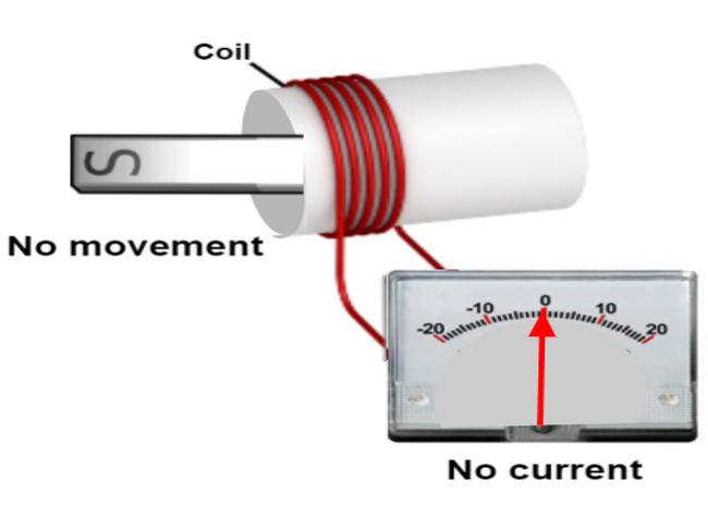
Ek coil ko galvanometer se attach kiya aur us coil ke paas ek magnet rakh diya. Coil ke aas pass magnetic field produce hui. Unhone socha ki jab coil ke aas pass magnetic field produce ho rahi hai to coil me electricity generate hona chahiye lekin galvanometer me koi deflection nahi hua yani ki coil me current produce nahi hua. Phir unhone magnet ko coil me move kiya aur tab observe kiya ki galvanometer me deflection ho raha hai aur coil me current induce ho raha hai.Ager hum magnet ko coil ke paas move krenge to coil me current flow hoga aur galvanometer me deflection hoga. Jab magnet rest pr hota hai to uski magnetic field change nahi hoti hai lekin jab magnet move krta hai to uski magnetic field coil ke respect me change ho jati hai. Change in Magnetic field current ko induce krti hai.
Is tarah se unhone discovery kiya ki jab bhi magnet coil ke paas jaye ya dur jaye, coil me current produce hota hai. Jab magnet paas jata hai, to magnetic lines of forces jo coil se paas ho rahi hai, unka number badh jata hai. Magnet ko dur le jane se coil se paas hone wali magnetic lines of forces ka number km ho jata hai. Coil ko magnet ke paas ya dur le jane se farak nahi parta usse sirf magnet ki motion se farak parta hai.
Direction of Induced Current:
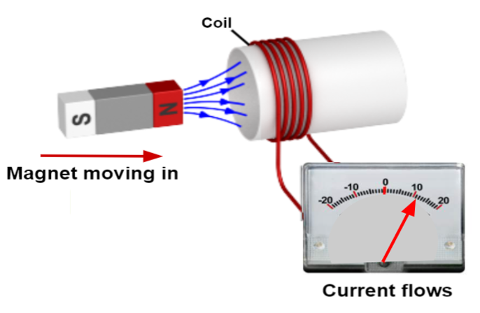
1. Jab coil me current flow nahi krta hai tab galvanometer ka pointer zero pr hota hai.2. Jab magnet ka North pole coil ke towards move krta hai, to current anticlockwise direction me flow krta hai aur galvanometer right deflect krta hai.
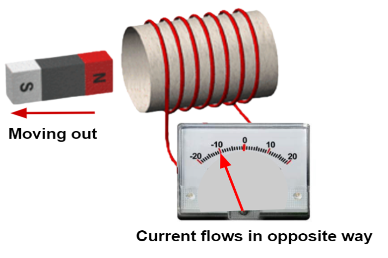
3. Jab magnet coil se dur move krta hai, to current clockwise direction me flow krta hai aur galvanometer left deflect krta hai.
Hence, relative motion between the magnet and the coil is responsible for generation (induction) of electric current in the coil.
EXPERIMENT 2
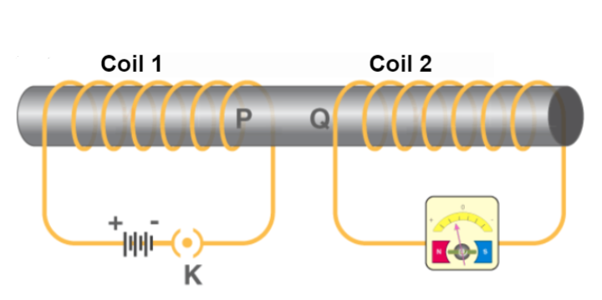
Is experiment me, Michael Faraday ne magnet ko ek dusre coil se replace kr diya aur usse battery se connect kr diya. Second coil me jo constant current hai wo constant magnetic field produce krega. Jab second coil first coil ke towards move krega, to galvanometer me deflection hoga, iska mtlb first coil me current induce hoga. Jab second coil ko fixed rakh kr first coil ko move kraya gya to bhi unhone same chiz observe kra.
Hence, relative motion between the coils induces the electric current.
EXPERIMENT 3
Is experiment me Faraday ne ye show kiya ki magnet aur coil ya do coils ke beech ka relative motion absolute requirement nahi hai. Unhone ek coil galvanometer se connect kra aur ek coil battery se connect kra. Unhone observe kra ki key press krne pr galvanometer maximum deflection show kr raha hai. Jab key ko continuously press krenge to galvanometer me koi deflection nahi hoga. Jab key ko release krenge to galvanometer phir se maximum deflection show krega pr opposite direction me. Unhone ye bhi observe kra ki jab iron rod ko dono coils ke axis ke along insert krenge to deflection increase hoga.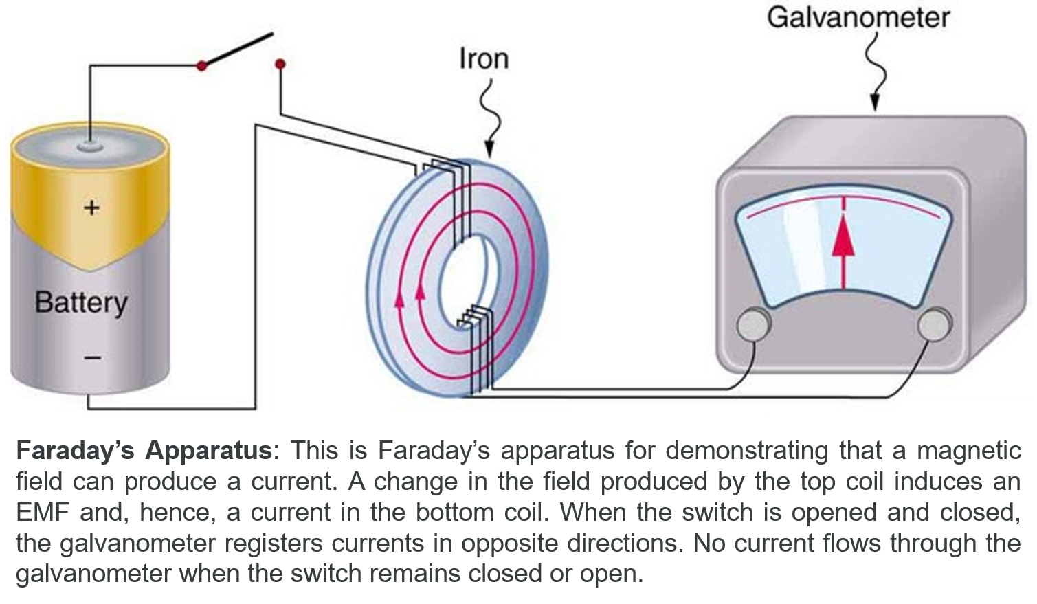
Faraday’s Apparatus: This is Faraday’s apparatus for demonstrating that a magnetic field can produce a current. A change in the field produced by the top coil induces an EMF and, hence, a current in the bottom coil. When the switch is opened and closed, the galvanometer registers currents in opposite directions. No current flows through the galvanometer when the switch remains closed or open.
Conclusion of Faraday's Experiment
1. The galvanometer shows deflection (i.e., an induced current flows in the coil) only when there is a relative motion between the coil and the magnet.2. The direction of deflection (i.e., of the induced current in the coil) is reversed if the direction of relative motion between the two coils and the magnet is reversed.
3. The deflection in the galvanometer (i.e., the induced current in the coil) increases if the magnet and the coil are rapidly moved with respect to each other.
MAGNETIC FLUX
Humne electric flux padha hai ϕe=→E.→AMagnetic flux ϕB=→B.→A
Magnetic flux is the dot product of magnetic field and area vector. Do vector ke dot product se magnetic flux mil raha hai isliye ye scalar quantity hai iska unit weber (Wb) hota hai.
Maan lo ki uniform magnetic field B hai. Jisme koi open surface A hai jisme area vector perpendicular to surface hota hai.
Magnetic flux : Number of magnetic field lines crossing through perpendicular to the surface
Ager surface ko θ angle pr ghuma diya jaye aur ager surface ka area badha diya jaye to jyada magnetic field line gujaregi.
Jab loop ka area aur magnetic field parallel hai to maximum magnetic field cross hogi aur perpendicular to surface hogi to minimum flux cross hogi. Surface area →A ke do components lenge Acosθ and Asinθ
Hume perpendicular field lines calculate karni hai jo B.Acostheta hai yahi magnetic flux hai.
ϕB=B.Acosθ
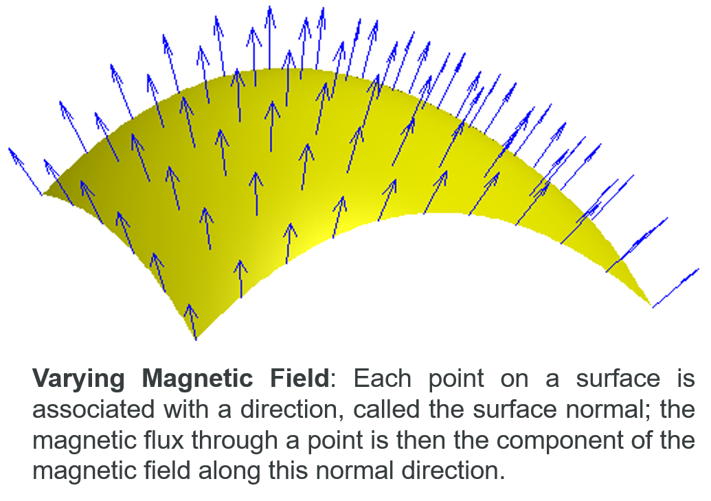
Varying Magnetic Field: Each point on a surface is associated with a direction, called the surface normal; the magnetic flux through a point is then the component of the magnetic field along this normal direction.
Kisi bhi area se gujarne wali number of magnetic field lines ko magnetic flux kahte hai. Ager chhota area hoga to use km flux jayega aur badha area hoga to usse jyada flux jayega. So, magnetic flux is proportional to area (ϕ∝A).
Ager kisi area pr magnetic field jyada hoga to number of magnetic field lines through the surface bhi jyada hogi yani ki flux jyada hoga. So, magnetic flux is proportional to the magnetic field (ϕ∝B).
Ager area vector positive hai, aur magnetic field aur area dono same direction me hain, to magnetic flux sbse jyada hoga aur dono ke beech ka angle zero hoga. Jab magnetic field aur area ke beech ka angle 90degree hoga tab magnetic flux zero hoga. So, magnetic flux is proportional to the angle between the magnetic field and area vector (ϕ∝cosθ).
Therefore, ϕ=BAcosθ

OMR (One Minute Revision)
- * It is a change in the magnetic field flux that results in an electromotive force (or voltage).
* The magnetic flux (often denoted Φ or ΦB) through a surface is the component of the magnetic field passing through that surface.
* In the most general form, magnetic flux is defined as ΦB=∬AB⋅dA. It is the integral (sum) of all of the magnetic field passing through infinitesimal area elements dA.
* The crucial quantity in induction is magnetic flux Φ, defined to be Φ=BAcosθ, where B is the magnetic field strength over an area A at an angle θ with the perpendicular to the area.
* Units of magnetic flux Φ are T⋅m2.
* Any change in magnetic flux Φ induces an emf—the process is defined to be electromagnetic induction.
THE EXPERIMENTS OF FARADAY’S AND HENRY
Michael Faraday ne socha ki ager electricity se magnetism produce ho raha hai to kya magnetism se electricity produce ho sakta hai? Iska answer find krne ke liye unhone 6 saal tak kafi experiments kiye.
EXPERIMENT 1
Ek coil ko galvanometer se attach kiya aur us coil ke paas ek magnet rakh diya. Coil ke aas pass magnetic field produce hui. Unhone socha ki jab coil ke aas pass magnetic field produce ho rahi hai to coil me electricity generate hona chahiye lekin galvanometer me koi deflection nahi hua yani ki coil me current produce nahi hua. Phir unhone magnet ko coil me move kiya aur tab observe kiya ki galvanometer me deflection ho raha hai aur coil me current induce ho raha hai.Ager hum magnet ko coil ke paas move krenge to coil me current flow hoga aur galvanometer me deflection hoga. Jab magnet rest pr hota hai to uski magnetic field change nahi hoti hai lekin jab magnet move krta hai to uski magnetic field coil ke respect me change ho jati hai. Change in Magnetic field current ko induce krti hai.
Is tarah se unhone discovery kiya ki jab bhi magnet coil ke paas jaye ya dur jaye, coil me current produce hota hai. Jab magnet paas jata hai, to magnetic lines of forces jo coil se paas ho rahi hai, unka number badh jata hai. Magnet ko dur le jane se coil se paas hone wali magnetic lines of forces ka number km ho jata hai. Coil ko magnet ke paas ya dur le jane se farak nahi parta usse sirf magnet ki motion se farak parta hai.
Direction of Induced Current:
1. Jab coil me current flow nahi krta hai tab galvanometer ka pointer zero pr hota hai.2. Jab magnet ka North pole coil ke towards move krta hai, to current anticlockwise direction me flow krta hai aur galvanometer right deflect krta hai.
3. Jab magnet coil se dur move krta hai, to current clockwise direction me flow krta hai aur galvanometer left deflect krta hai.
Hence, relative motion between the magnet and the coil is responsible for generation (induction) of electric current in the coil.


EXPERIMENT 2

Is experiment me, Michael Faraday ne magnet ko ek dusre coil se replace kr diya aur usse battery se connect kr diya. Second coil me jo constant current hai wo constant magnetic field produce krega. Jab second coil first coil ke towards move krega, to galvanometer me deflection hoga, iska mtlb first coil me current induce hoga. Jab second coil ko fixed rakh kr first coil ko move kraya gya to bhi unhone same chiz observe kra.
Hence, relative motion between the coils induces the electric current.
EXPERIMENT 3
Is experiment me Faraday ne ye show kiya ki magnet aur coil ya do coils ke beech ka relative motion absolute requirement nahi hai. Unhone ek coil galvanometer se connect kra aur ek coil battery se connect kra. Unhone observe kra ki key press krne pr galvanometer maximum deflection show kr raha hai. Jab key ko continuously press krenge to galvanometer me koi deflection nahi hoga. Jab key ko release krenge to galvanometer phir se maximum deflection show krega pr opposite direction me. Unhone ye bhi observe kra ki jab iron rod ko dono coils ke axis ke along insert krenge to deflection increase hoga.
Faraday’s Apparatus: This is Faraday’s apparatus for demonstrating that a magnetic field can produce a current. A change in the field produced by the top coil induces an EMF and, hence, a current in the bottom coil. When the switch is opened and closed, the galvanometer registers currents in opposite directions. No current flows through the galvanometer when the switch remains closed or open.
Conclusion of Faraday's Experiment
1. The galvanometer shows deflection (i.e., an induced current flows in the coil) only when there is a relative motion between the coil and the magnet.2. The direction of deflection (i.e., of the induced current in the coil) is reversed if the direction of relative motion between the two coils and the magnet is reversed.
3. The deflection in the galvanometer (i.e., the induced current in the coil) increases if the magnet and the coil are rapidly moved with respect to each other.
MAGNETIC FLUX
Humne electric flux padha hai ϕe=→E.→AMagnetic flux ϕB=→B.→A
Magnetic flux is the dot product of magnetic field and area vector. Do vector ke dot product se magnetic flux mil raha hai isliye ye scalar quantity hai iska unit weber (Wb) hota hai.
Maan lo ki uniform magnetic field B hai. Jisme koi open surface A hai jisme area vector perpendicular to surface hota hai.
Magnetic flux : Number of magnetic field lines crossing through perpendicular to the surface
Ager surface ko θ angle pr ghuma diya jaye aur ager surface ka area badha diya jaye to jyada magnetic field line gujaregi.
Jab loop ka area aur magnetic field parallel hai to maximum magnetic field cross hogi aur perpendicular to surface hogi to minimum flux cross hogi. Surface area →A ke do components lenge Acosθ and Asinθ
Hume perpendicular field lines calculate karni hai jo B.Acostheta hai yahi magnetic flux hai.
ϕB=B.Acosθ

Varying Magnetic Field: Each point on a surface is associated with a direction, called the surface normal; the magnetic flux through a point is then the component of the magnetic field along this normal direction.
Kisi bhi area se gujarne wali number of magnetic field lines ko magnetic flux kahte hai. Ager chhota area hoga to use km flux jayega aur badha area hoga to usse jyada flux jayega. So, magnetic flux is proportional to area (ϕ∝A).
Ager kisi area pr magnetic field jyada hoga to number of magnetic field lines through the surface bhi jyada hogi yani ki flux jyada hoga. So, magnetic flux is proportional to the magnetic field (ϕ∝B).
Ager area vector positive hai, aur magnetic field aur area dono same direction me hain, to magnetic flux sbse jyada hoga aur dono ke beech ka angle zero hoga. Jab magnetic field aur area ke beech ka angle 90degree hoga tab magnetic flux zero hoga. So, magnetic flux is proportional to the angle between the magnetic field and area vector (ϕ∝cosθ).
Therefore, ϕ=BAcosθ

OMR (One Minute Revision)
- * It is a change in the magnetic field flux that results in an electromotive force (or voltage).
* The magnetic flux (often denoted Φ or ΦB) through a surface is the component of the magnetic field passing through that surface.
* In the most general form, magnetic flux is defined as ΦB=∬AB⋅dA. It is the integral (sum) of all of the magnetic field passing through infinitesimal area elements dA.
* The crucial quantity in induction is magnetic flux Φ, defined to be Φ=BAcosθ, where B is the magnetic field strength over an area A at an angle θ with the perpendicular to the area.
* Units of magnetic flux Φ are T⋅m2.
* Any change in magnetic flux Φ induces an emf—the process is defined to be electromagnetic induction.
THE EXPERIMENTS OF FARADAY’S AND HENRY
Michael Faraday ne socha ki ager electricity se magnetism produce ho raha hai to kya magnetism se electricity produce ho sakta hai? Iska answer find krne ke liye unhone 6 saal tak kafi experiments kiye.
EXPERIMENT 1
Ek coil ko galvanometer se attach kiya aur us coil ke paas ek magnet rakh diya. Coil ke aas pass magnetic field produce hui. Unhone socha ki jab coil ke aas pass magnetic field produce ho rahi hai to coil me electricity generate hona chahiye lekin galvanometer me koi deflection nahi hua yani ki coil me current produce nahi hua. Phir unhone magnet ko coil me move kiya aur tab observe kiya ki galvanometer me deflection ho raha hai aur coil me current induce ho raha hai.Ager hum magnet ko coil ke paas move krenge to coil me current flow hoga aur galvanometer me deflection hoga. Jab magnet rest pr hota hai to uski magnetic field change nahi hoti hai lekin jab magnet move krta hai to uski magnetic field coil ke respect me change ho jati hai. Change in Magnetic field current ko induce krti hai.
Is tarah se unhone discovery kiya ki jab bhi magnet coil ke paas jaye ya dur jaye, coil me current produce hota hai. Jab magnet paas jata hai, to magnetic lines of forces jo coil se paas ho rahi hai, unka number badh jata hai. Magnet ko dur le jane se coil se paas hone wali magnetic lines of forces ka number km ho jata hai. Coil ko magnet ke paas ya dur le jane se farak nahi parta usse sirf magnet ki motion se farak parta hai.
Direction of Induced Current:
1. Jab coil me current flow nahi krta hai tab galvanometer ka pointer zero pr hota hai.2. Jab magnet ka North pole coil ke towards move krta hai, to current anticlockwise direction me flow krta hai aur galvanometer right deflect krta hai.
3. Jab magnet coil se dur move krta hai, to current clockwise direction me flow krta hai aur galvanometer left deflect krta hai.
Hence, relative motion between the magnet and the coil is responsible for generation (induction) of electric current in the coil.


EXPERIMENT 2

Is experiment me, Michael Faraday ne magnet ko ek dusre coil se replace kr diya aur usse battery se connect kr diya. Second coil me jo constant current hai wo constant magnetic field produce krega. Jab second coil first coil ke towards move krega, to galvanometer me deflection hoga, iska mtlb first coil me current induce hoga. Jab second coil ko fixed rakh kr first coil ko move kraya gya to bhi unhone same chiz observe kra.
Hence, relative motion between the coils induces the electric current.
EXPERIMENT 3
Is experiment me Faraday ne ye show kiya ki magnet aur coil ya do coils ke beech ka relative motion absolute requirement nahi hai. Unhone ek coil galvanometer se connect kra aur ek coil battery se connect kra. Unhone observe kra ki key press krne pr galvanometer maximum deflection show kr raha hai. Jab key ko continuously press krenge to galvanometer me koi deflection nahi hoga. Jab key ko release krenge to galvanometer phir se maximum deflection show krega pr opposite direction me. Unhone ye bhi observe kra ki jab iron rod ko dono coils ke axis ke along insert krenge to deflection increase hoga.
Faraday’s Apparatus: This is Faraday’s apparatus for demonstrating that a magnetic field can produce a current. A change in the field produced by the top coil induces an EMF and, hence, a current in the bottom coil. When the switch is opened and closed, the galvanometer registers currents in opposite directions. No current flows through the galvanometer when the switch remains closed or open.
Conclusion of Faraday's Experiment
1. The galvanometer shows deflection (i.e., an induced current flows in the coil) only when there is a relative motion between the coil and the magnet.2. The direction of deflection (i.e., of the induced current in the coil) is reversed if the direction of relative motion between the two coils and the magnet is reversed.
3. The deflection in the galvanometer (i.e., the induced current in the coil) increases if the magnet and the coil are rapidly moved with respect to each other.
MAGNETIC FLUX
Humne electric flux padha hai ϕe=→E.→AMagnetic flux ϕB=→B.→A
Magnetic flux is the dot product of magnetic field and area vector. Do vector ke dot product se magnetic flux mil raha hai isliye ye scalar quantity hai iska unit weber (Wb) hota hai.
Maan lo ki uniform magnetic field B hai. Jisme koi open surface A hai jisme area vector perpendicular to surface hota hai.
Magnetic flux : Number of magnetic field lines crossing through perpendicular to the surface
Ager surface ko θ angle pr ghuma diya jaye aur ager surface ka area badha diya jaye to jyada magnetic field line gujaregi.
Jab loop ka area aur magnetic field parallel hai to maximum magnetic field cross hogi aur perpendicular to surface hogi to minimum flux cross hogi. Surface area →A ke do components lenge Acosθ and Asinθ
Hume perpendicular field lines calculate karni hai jo B.Acostheta hai yahi magnetic flux hai.
ϕB=B.Acosθ

Varying Magnetic Field: Each point on a surface is associated with a direction, called the surface normal; the magnetic flux through a point is then the component of the magnetic field along this normal direction.
Kisi bhi area se gujarne wali number of magnetic field lines ko magnetic flux kahte hai. Ager chhota area hoga to use km flux jayega aur badha area hoga to usse jyada flux jayega. So, magnetic flux is proportional to area (ϕ∝A).
Ager kisi area pr magnetic field jyada hoga to number of magnetic field lines through the surface bhi jyada hogi yani ki flux jyada hoga. So, magnetic flux is proportional to the magnetic field (ϕ∝B).
Ager area vector positive hai, aur magnetic field aur area dono same direction me hain, to magnetic flux sbse jyada hoga aur dono ke beech ka angle zero hoga. Jab magnetic field aur area ke beech ka angle 90degree hoga tab magnetic flux zero hoga. So, magnetic flux is proportional to the angle between the magnetic field and area vector (ϕ∝cosθ).
Therefore, ϕ=BAcosθ

OMR (One Minute Revision)
- * It is a change in the magnetic field flux that results in an electromotive force (or voltage).
* The magnetic flux (often denoted Φ or ΦB) through a surface is the component of the magnetic field passing through that surface.
* In the most general form, magnetic flux is defined as ΦB=∬AB⋅dA. It is the integral (sum) of all of the magnetic field passing through infinitesimal area elements dA.
* The crucial quantity in induction is magnetic flux Φ, defined to be Φ=BAcosθ, where B is the magnetic field strength over an area A at an angle θ with the perpendicular to the area.
* Units of magnetic flux Φ are T⋅m2.
* Any change in magnetic flux Φ induces an emf—the process is defined to be electromagnetic induction.
POINT 1
POINT 1
POINT 1
FARADAY’S LAW OF INDUCTION
Magnetic flux ke change hone se hi current induce hogi. Magnetic flux change hone ke three case ho sakte hai. Magnetic field ka change hona, Area ka change hona ya fr magnetic flux aur area ke bich ka angle change hona. Inme se kisi bhi ek me bhi change aaye to magnetic flux change hogi. (Wo area lena hai jiski surface perpendicular ho magnetic field ke)
ε=−dΦBdt
Emf induced in a loop is equal to rate of change of flux. Ager km time me jyada flux change hoga jyada induced emf hoga. Change of flux me depend nahi kr raha hai balki is chij pe depend kr raha hai ki flux kiss rate se change kr raha hai. Emf is chij pe depend nahi kr raha hai ki flux kitna change ho raha hai balki emf is chij pe depend kr raha hai ki flux kitni teji se change ho raha hai.
ε=−ddtB.Acosθ
Jab time ke sath magnetic field B change hoga.
ε=−AcosθdBdt
Jab time ke sath area A change hoga.
ε=−BcosθdAdt
Jab time ke sath magnetic field B aur area A ke bich angle θ change hoga.
ε=−BAddtcosθ
Ek sath do variables change nahi honge.
OMR (One Minute Revision)
- * Faraday’s law of induction states that the emf induced by a change in magnetic flux is emf=−NΔΦΔt when flux changes by ΔΦ in a time Δt.
* If emf is induced in a coil, N is its number of turns.
* The minus in Faraday's law means that the EMF creates a current I and magnetic field B that oppose the change in flux ΔΦ this is known as Lenz’ law.
* Faraday’s law of induction is the fundamental operating principle of transformers, inductors, and many types of electrical motors, generators, and solenoids.
* Faraday’s law states that the EMF induced by a change in magnetic flux depends on the change in flux Δ, time Δt, and number of turns of coils.
POINT 2
The units for magnetic flux are webers, where 1Wb=1T⋅m2. The induced emf in a closed loop due to a change in magnetic flux through the loop is known as Faraday’s law. If there is no change in magnetic flux, no induced emf is created.
POINT 2
The units for magnetic flux are webers, where 1Wb=1T⋅m2. The induced emf in a closed loop due to a change in magnetic flux through the loop is known as Faraday’s law. If there is no change in magnetic flux, no induced emf is created.
POINT 2
The units for magnetic flux are webers, where 1Wb=1T⋅m2. The induced emf in a closed loop due to a change in magnetic flux through the loop is known as Faraday’s law. If there is no change in magnetic flux, no induced emf is created.
EXAMPLE 1
Consider a magnet surrounded by a wire with an on/off switch S (figure). If the switch is thrown from the off position (open circuit) to the on position (closed circuit), will a current flow in the circuit ? Explain.

When the switch is thrown from the off position (open circuit) to the position (closed circuit), then neither B, nor A nor the angle between B and A change. Thus, no change in magnetic flux linked with the coil occur. Hence no electromotive force is produced and consequently no current will flow in the circuit.
EXAMPLE 1
Consider a magnet surrounded by a wire with an on/off switch S (figure). If the switch is thrown from the off position (open circuit) to the on position (closed circuit), will a current flow in the circuit ? Explain.

When the switch is thrown from the off position (open circuit) to the position (closed circuit), then neither B, nor A nor the angle between B and A change. Thus, no change in magnetic flux linked with the coil occur. Hence no electromotive force is produced and consequently no current will flow in the circuit.
EXAMPLE 1
Consider a magnet surrounded by a wire with an on/off switch S (figure). If the switch is thrown from the off position (open circuit) to the on position (closed circuit), will a current flow in the circuit ? Explain.

When the switch is thrown from the off position (open circuit) to the position (closed circuit), then neither B, nor A nor the angle between B and A change. Thus, no change in magnetic flux linked with the coil occur. Hence no electromotive force is produced and consequently no current will flow in the circuit.
EXAMPLE 2
A magnetic field in a certain region is given by B=B0cos(ωt)ˆk and a coil of radius a with resistance R is placed in the x−y plane with its centre at the origin in the magnetic field (figure). Find the magnitude and the direction of the current at (a,0,0) at
t=π2ω,t=πωandt=3π2ω
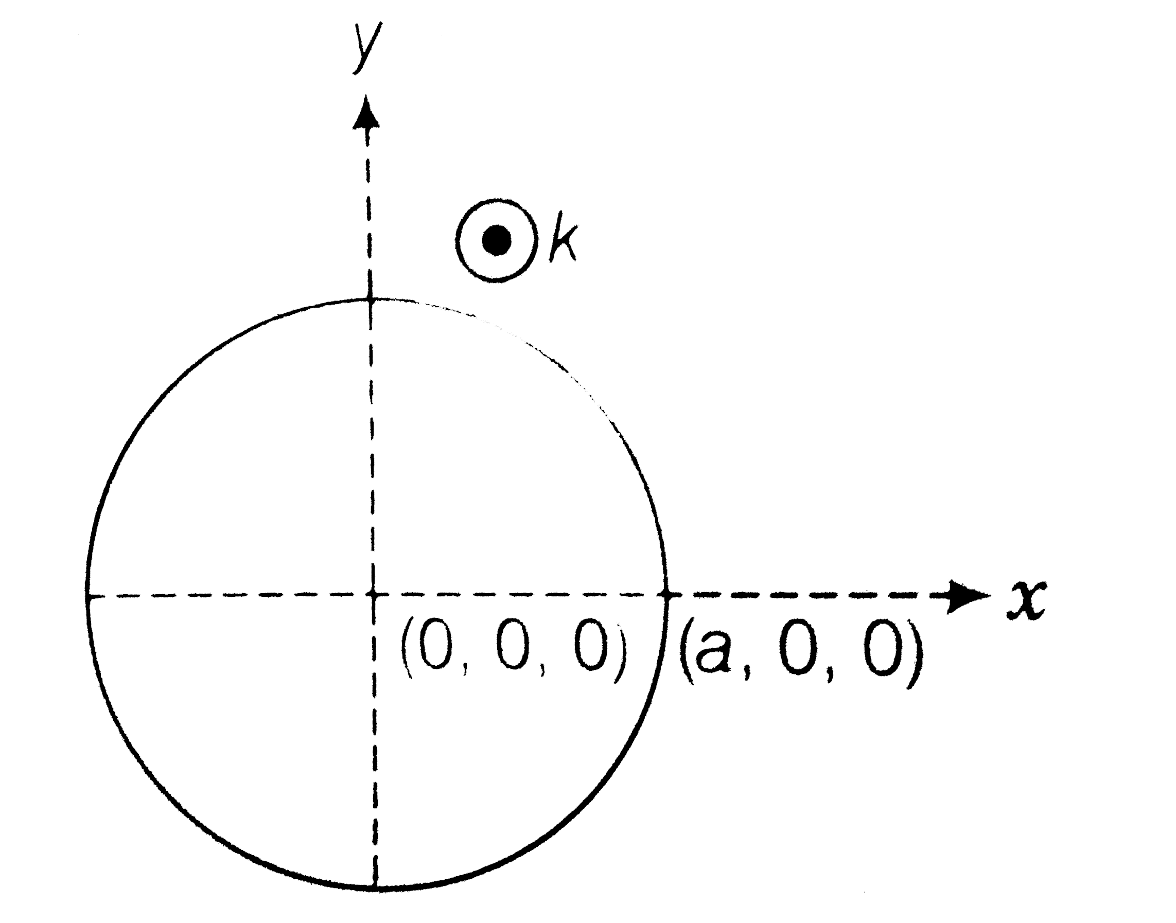
At any instant, flux passes through the ring is given by ϕ=B.A=Bacosθ=BA
or ϕ=B0(πa2)cosωt
By Faraday's law of electromagnetic induction, Magnitude of induced emf is given by ε=B0(πa2)ωsinωt
This causes flow of induced current, which is given by
I=B0(πa2)ωsinωt/R2
Now,finding the value of current at different instants, so we have current at
t=π2ω
I=B0(πa2)ωRalongˆj
Because sinωt=sin(ωπ2ω)=sin,π2=1
=πωI=B(πa2)ωR
Here, sinωt=sin(ω=πω)=sinπ=0
t=32πω
I=B(πa2)ωRalong−ˆj
sinωt=sin(ω3π2ω)=sin,3π2=1
EXAMPLE 2
A magnetic field in a certain region is given by B=B0cos(ωt)ˆk and a coil of radius a with resistance R is placed in the x−y plane with its centre at the origin in the magnetic field (figure). Find the magnitude and the direction of the current at (a,0,0) at
t=π2ω,t=πωandt=3π2ω

At any instant, flux passes through the ring is given by ϕ=B.A=Bacosθ=BA
or ϕ=B0(πa2)cosωt
By Faraday's law of electromagnetic induction, Magnitude of induced emf is given by ε=B0(πa2)ωsinωt
This causes flow of induced current, which is given by
I=B0(πa2)ωsinωt/R2
Now,finding the value of current at different instants, so we have current at
t=π2ω
I=B0(πa2)ωRalongˆj
Because sinωt=sin(ωπ2ω)=sin,π2=1
=πωI=B(πa2)ωR
Here, sinωt=sin(ω=πω)=sinπ=0
t=32πω
I=B(πa2)ωRalong−ˆj
sinωt=sin(ω3π2ω)=sin,3π2=1
EXAMPLE 2
A magnetic field in a certain region is given by B=B0cos(ωt)ˆk and a coil of radius a with resistance R is placed in the x−y plane with its centre at the origin in the magnetic field (figure). Find the magnitude and the direction of the current at (a,0,0) at
t=π2ω,t=πωandt=3π2ω

At any instant, flux passes through the ring is given by ϕ=B.A=Bacosθ=BA
or ϕ=B0(πa2)cosωt
By Faraday's law of electromagnetic induction, Magnitude of induced emf is given by ε=B0(πa2)ωsinωt
This causes flow of induced current, which is given by
I=B0(πa2)ωsinωt/R2
Now,finding the value of current at different instants, so we have current at
t=π2ω
I=B0(πa2)ωRalongˆj
Because sinωt=sin(ωπ2ω)=sin,π2=1
=πωI=B(πa2)ωR
Here, sinωt=sin(ω=πω)=sinπ=0
t=32πω
I=B(πa2)ωRalong−ˆj
sinωt=sin(ω3π2ω)=sin,3π2=1
EXAMPLE 3
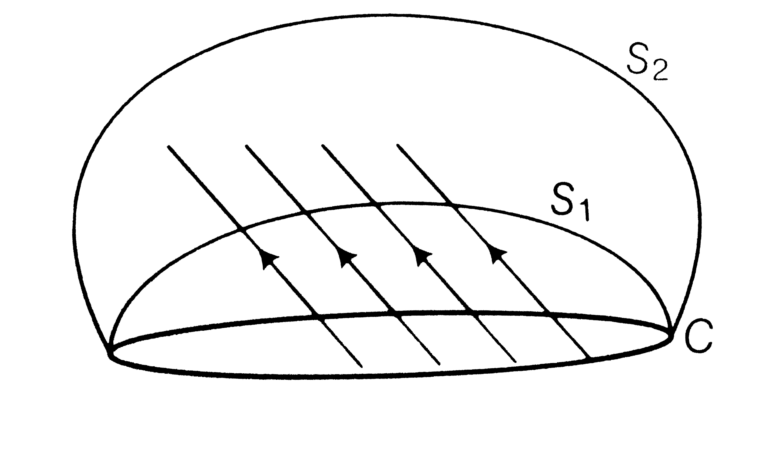
Consider a closed loop C in a magnetic field. The flux passing through the loop is defined by choosing the surface whose edge coincides with the loop and using the formula ϕ=B1dA1,B2dA2....... Now, if we choose two different surfaces, S1 and S2 having C as their edge, would get the same answer for flux. Justify your answer.
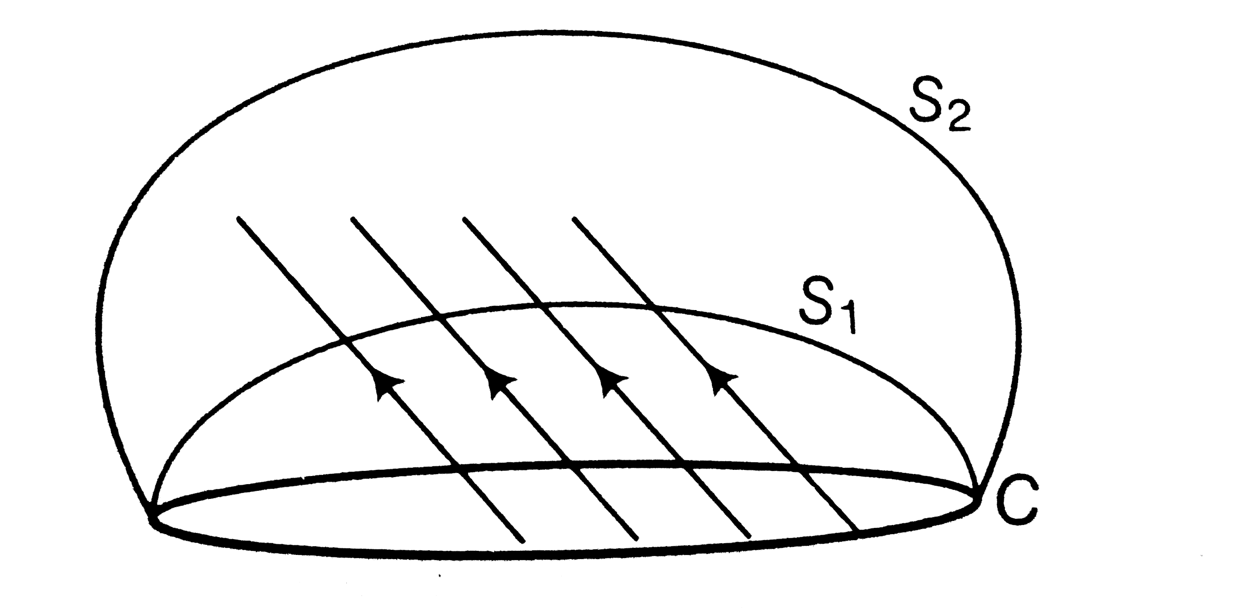
The magnetic flux linked with the surface can considered as the number of magnetic field lines passing through the surface. So, let dϕ=BA represents magnetic lines in an area A to B.
By the concept of continuity of lines B cannot end or start in space, therefore the number of lines passing through surface S1 must be the same as the number of lines passing through the surface S2. Therefore, in both the cases we get the same answer for flux.
EXAMPLE 3
Show a conduction loop placed near a long, straight wire carrying current i as shown. If the current increases continuously, find the direction of the induced current in the loop.
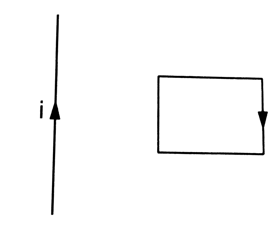
Let us put an arrow on the loop as shows in the figure
The right- hand thumb rule shows that the positive normal to the loop is going into the plane of the diagram
Also, the same rule shows that the magnetic field at the site of the loop due ot the current is also going into the plane of hte diagram
Thus, →B and dvacS are along the same direction everywhere so that the flux Φ=∫→B<br>d→S is positive
If i increases, the magnitude of Φ increases
Since Φ is positive and its magnitude increases, dΦdt is positive
Thus varepsilon is nagative and hence, the current is negative
The ɛ is negative and hence, the current is negative
the current is, therefore, induced in the direction opposite to the arrow.
EXAMPLE 3
Show a conduction loop placed near a long, straight wire carrying current i as shown. If the current increases continuously, find the direction of the induced current in the loop.

Let us put an arrow on the loop as shows in the figure
The right- hand thumb rule shows that the positive normal to the loop is going into the plane of the diagram
Also, the same rule shows that the magnetic field at the site of the loop due ot the current is also going into the plane of hte diagram
Thus, →B and dvacS are along the same direction everywhere so that the flux Φ=∫→B<br>d→S is positive
If i increases, the magnitude of Φ increases
Since Φ is positive and its magnitude increases, dΦdt is positive
Thus ɛ is nagative and hence, the current is negative
The ɛ is negative and hence, the current is negative
the current is, therefore, induced in the direction opposite to the arrow.
EXAMPLE 4
A rectangular loop of wire ABCD is kept close to an infinitely long wire carring a current I (t) =I0(1=t/T) for 0≤t≤ and I (0) for t gt T, Fig. Find the total charges passing through a given point in the loop, in time T. resistance of the loop is R
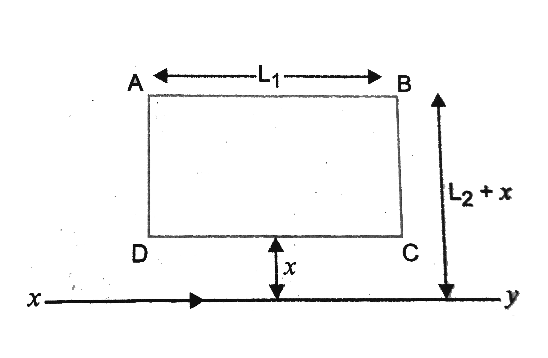
In Fig. XY is an infinitely long wire carruying current
I(t)=I0(1−t/T) for 0≤t≤T
If I (t) is current induced in the loop, then
I(t)=dϕ/dtR=dQdt
Integrating both sides, we get Q(t1)=Q(t2)=1R[ϕ(t1)−ϕ(t2)]
using (i) of Q .25 , ϕ(t1)=L1μ02π∫L2+xxdx'x'I(t1)=μ0L12πI(t1)loge(L2+xx)
∴ The magnitude of charge would be Q=μ0L12πloge(L1+xx)[I1−0]=μ0L1I12πloge(L2+xx)
EXAMPLE 4
A rectangular loop of wire ABCD is kept close to an infinitely long wire carring a current I (t) =I0(1=t/T) for 0≤t≤ and I (0) for t gt T, Fig. Find the total charges passing through a given point in the loop, in time T. resistance of the loop is R

In Fig. XY is an infinitely long wire carruying current
I(t)=I0(1−t/T) for 0≤t≤T
If I (t) is current induced in the loop, then
I(t)=dϕ/dtR=dQdt
Integrating both sides, we get Q(t1)=Q(t2)=1R[ϕ(t1)−ϕ(t2)]
using (i) of Q .25 , ϕ(t1)=L1μ02π∫L2+xxdx'x'I(t1)=μ0L12πI(t1)loge(L2+xx)
∴ The magnitude of charge would be Q=μ0L12πloge(L1+xx)[I1−0]=μ0L1I12πloge(L2+xx)
EXAMPLE 4
A rectangular loop of wire ABCD is kept close to an infinitely long wire carring a current I (t) =I0(1=t/T) for 0≤t≤ and I (0) for t gt T, Fig. Find the total charges passing through a given point in the loop, in time T. resistance of the loop is R

In Fig. XY is an infinitely long wire carruying current
I(t)=I0(1−t/T) for 0≤t≤T
If I (t) is current induced in the loop, then
I(t)=dϕ/dtR=dQdt
Integrating both sides, we get Q(t1)=Q(t2)=1R[ϕ(t1)−ϕ(t2)]
using (i) of Q .25 , ϕ(t1)=L1μ02π∫L2+xxdx'x'I(t1)=μ0L12πI(t1)loge(L2+xx)
∴ The magnitude of charge would be Q=μ0L12πloge(L1+xx)[I1−0]=μ0L1I12πloge(L2+xx)
EXAMPLE 5
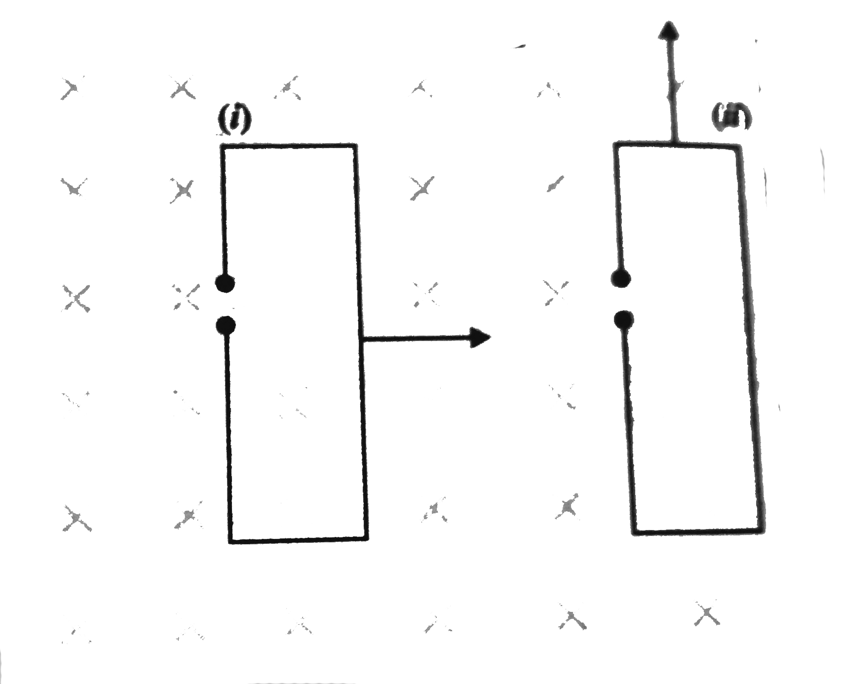
A rectangular loop of sides 8 cm and 2 cm with a small cut is moving out of a region of uniform megnetic field of magnitude 0.3 tesla directed normal to the loop. What is the voltage developed acorss the cut if velocity of the loop is 1cms−1 in a direction normal to the (i) longer side (ii) shorter side of the loop ? For how long does the induced voltage last in each case?
Here, A=8×2=16cm2=16×10−4m2,B=0.3 tesla, υ=1cm/sec=102ms−1
induced e.m.f. = e = ?
(i) When velocity is normal to longer side,
l=8cm=8×10⁻²m
e=Blυ=0.3×8×10−2×10−2
=2.4×10⁻⁴V
Time, t=distance movedvelocity=2×10−210−2=2 side,
(ii) When velocity is normal to shorter side,
l=2cm=2×10⁻²cm
e=Blυ=0.3×2×10−2×10−2=0.6V
Time, t=distance movedvelocity=8×10−210−2=8sec
Note that induced voltage lasts in each case, so long as the loop is partially in the magnetic field.
EXAMPLE 5
Fig. Show a rectangular loop MNOP being pulled out of a magnetic field with a uniform velocity v by applying an external force F. The length MN is equal to l and the total resistance of the loop is R. Find(a) the current in the loop,(b) the magnetic force on the loop, (c) the external force F needed to maintain the velocity, (d) the power delivered by the external force and (e) the thermal power developed in the loop.

(a) The emf induced in the loop is due to the motion of the wire MN
The emf is ɛ=vBl with the positive end at N and the negative and at M
The current is I=(ɛ)(R)=vBIR in the clockwise direction
(b) The magnetic force on the wire MN is →F1=i→LX→B
The magnitude is F1=ilB=vB2l2R and is opposite to the velocity
the forces on the parts of the wire NO and PM, lying in the fijled, cancle each other
The resultant magnetic force on the loop is, therfore, F1=Bl^2vR opposite ot the velocity
(c)To move the loop at a constant velocity, the resultant force on it should be zero
Thus, one should pull the loop with a force F=F1=vB2l2R
(d) The power delivered by the external force is P=FV=v2B2l2R (e) The thermal power developed is P=l2R=(vBIR)2R=v2B2l2R
We see that the power delivered by the external force is equal to the thermal power developed in the loop
this is consistent with the principle of conservation of energy
EXAMPLE 5
Fig. Show a rectangular loop MNOP being pulled out of a magnetic field with a uniform velocity v by applying an external force F. The length MN is equal to l and the total resistance of the loop is R. Find(a) the current in the loop,(b) the magnetic force on the loop, (c) the external force F needed to maintain the velocity, (d) the power delivered by the external force and (e) the thermal power developed in the loop.

(a) The emf induced in the loop is due to the motion of the wire MN
The emf is ɛ=vBl with the positive end at N and the negative and at M
The current is I=(ɛ)(R)=vBIR in the clockwise direction
(b) The magnetic force on the wire MN is →F1=i→LX→B
The magnitude is F1=ilB=vB2l2R and is opposite to the velocity
the forces on the parts of the wire NO and PM, lying in the fijled, cancle each other
The resultant magnetic force on the loop is, therfore, F1=Bl^2vR opposite ot the velocity
(c)To move the loop at a constant velocity, the resultant force on it should be zero
Thus, one should pull the loop with a force F=F1=vB2l2R
(d) The power delivered by the external force is P=FV=v2B2l2R (e) The thermal power developed is P=l2R=(vBIR)2R=v2B2l2R
We see that the power delivered by the external force is equal to the thermal power developed in the loop
this is consistent with the principle of conservation of energy
EXAMPLE 6
(a) What would you do to obtain a large deflection of the galvanometer? (b) How would you demonstrate the presence of an induced current in the absence of a galvanometer?
(a) To obtain a large deflection, one or more of the following steps can be taken: (i) Use a rod made of soft iron inside the coil C2, (ii) Connect the coil to a powerful battery, and (iii) Move the arrangement rapidly towards the test coil C1.
(b) Replace the galvanometer by a small bulb, the kind one finds in a small torch light. The relative motion between the two coils will cause the bulb to glow and thus demonstrate the presence of an induced current.
EXAMPLE 6
An inductor (L=20mH), a resistor (R=100Ω) and a battery(ɛ=10V) are connected in series. Find (a) the time constant, (b) the maximum current and (c ) the time elapsed before the current reaches 99% of the maximum value.
(a) The time constant is τ=LR=20mH100Ω=0<br>20ms<br>(b)Themaxiμmcurrentis I = varepsilon /R = (10 V)/(100 Omega) = 0
10 A<br>(c)UsingI = i_0(1-e^(-t/tau), 0
99 i_0 = i_0(1-e^(-t/tau)or, e^(-t/tau) = 0
01)or,(t)/(tau) =- In(0
01)or,t = (0
20ms) In(100) = 0
92ms.
LENZ’S LAW AND CONSERVATION OF ENERGY
ε=−dΦBdt
I=εR=−1RdΦBdt
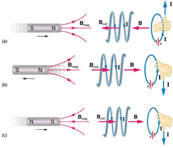
Kisi bhi loop me current aisi aayegi ki usi karan ka virodh karegi jiske karan aayi hai. Current kyu aai? Kyuki emf aaya. Emf kyu aya? Kyuki flux change hua aur current jo aayi wo isi flux ka oppose kr rahi. Ager flux badh raha hai to current aise produce hogi jo flux ko ghatane ki kosis karegi. Ager flux km horaha hai to aise produce hogi jo flux ko badhane ki kosis karegi. Magnetic field ek conservative force hai. Energy kaise conserve hoti hai? Maan lo ki do coil rakh diye jisme magnetic field badh raha hai bich ke volume me to isme apne aap aisi current aayegi ye current energy ko constant maintain karegi. Energy badh rahi hai per unit volume me to aisi current produce hogi ki is energy ko constant maintain karke rakhegi.

The statement of the law is: The polarity of induced emf is such that it tends to produce a current which opposes the change in magnetic flux that produced it.
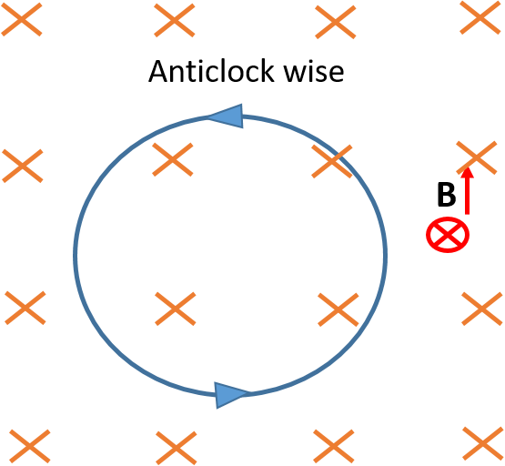
Ek coil hai jisme magnetic field badh raha hai ander ki taraf to is coil me current anticlock wise jayegi. Ye current chahegi ander ki taraf net flux jo badh raha hai usko counter karegi. Induced magnetic current bahar ki taraf magnetic field badhane ki kosis karega jisse ander ki taraf badh raha magnetic field counter hoga (shown in figure below).
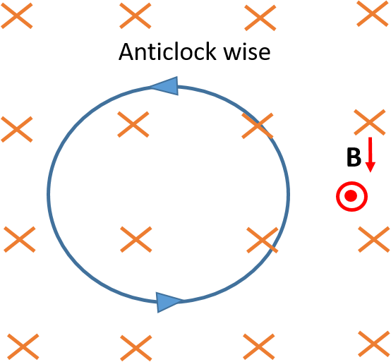
Ager kisi coil me bahar ki taraf magnetic field km ho raha hai to current aayegi kyuki flux change ho raha hai. Ye current km hote hue flux ko oppose karegi jiske liye ye apna magnetic field bahar de degi mtlb bahar ki taraf magnetic field ko apna magnetic field deke support karegi mtlb bahar ki taraf magnetic field ko badha degi. Kyuki magnetic flux km ho raha hai to magnetic current chahegi ki ye km hota hua flux km na ho kyuki yahi property hai ki current, change of flux ka oppose karta hai. Flux badhega to current use km karne ki kosis karegi aur jab flux km hoga to current us flux ko badhane ki kosis karegi (shown in below figure).
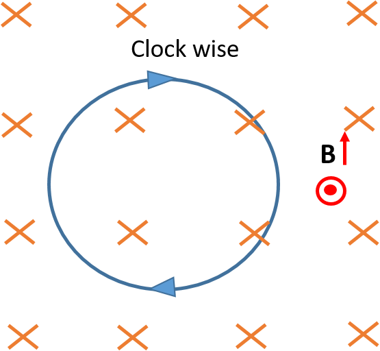
Ager magnetic field bahar ki taraf increase ho rahi hai to loop me current ki direction clockwise hogi (shown in below figure).
Kisi long infinite current carrying wire ke paas kisi loop me ander ki taraf magnetic field increase hoti hai to is loop me current ki direction anticlockwise hogi taki ander ki taraf increase ho rahe magnetic field ka oppose kr sake aur bahar ki taraf magnetic field produce kr sake(shown in below figure).
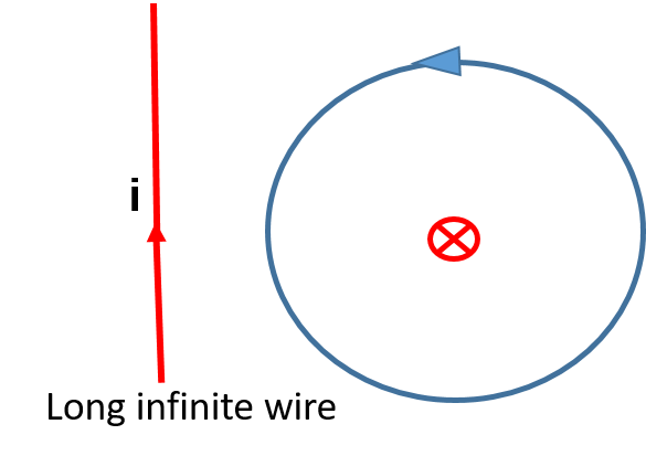
- Induced emf ya current ke liye magnitude deta hai faraday aur direction deta hai Lenz.
OMR (One Minute Revision)
- * Lenz’s law is a manifestation of the conservation of energy. The induced EMF produces a current that opposes the change in flux, because a change in flux means a change in energy. Energy can enter or leave, but not instantaneously. Lenz’s law is a consequence. As the change begins, the law says induction opposes and, thus, slows the change. In fact, if the induced EMF were in the same direction as the change in flux, there would be a positive feedback that would give us free energy from no apparent source—conservation of energy would be violated.
LENZ’S LAW AND CONSERVATION OF ENERGY
ε=−dΦBdt
I=εR=−1RdΦBdt
Kisi bhi loop me current aisi aayegi ki usi karan ka virodh karegi jiske karan aayi hai. Current kyu aai? Kyuki emf aaya. Emf kyu aya? Kyuki flux change hua aur current jo aayi wo isi flux ka oppose kr rahi. Ager flux badh raha hai to current aise produce hogi jo flux ko ghatane ki kosis karegi. Ager flux km horaha hai to aise produce hogi jo flux ko badhane ki kosis karegi. Magnetic field ek conservative force hai. Energy kaise conserve hoti hai? Maan lo ki do coil rakh diye jisme magnetic field badh raha hai bich ke volume me to isme apne aap aisi current aayegi ye current energy ko constant maintain karegi. Energy badh rahi hai per unit volume me to aisi current produce hogi ki is energy ko constant maintain karke rakhegi.

The statement of the law is: The polarity of induced emf is such that it tends to produce a current which opposes the change in magnetic flux that produced it.

Ek coil hai jisme magnetic field badh raha hai ander ki taraf to is coil me current anticlock wise jayegi. Ye current chahegi ander ki taraf net flux jo badh raha hai usko counter karegi. Induced magnetic current bahar ki taraf magnetic field badhane ki kosis karega jisse ander ki taraf badh raha magnetic field counter hoga (shown in figure below).

Ager kisi coil me bahar ki taraf magnetic field km ho raha hai to current aayegi kyuki flux change ho raha hai. Ye current km hote hue flux ko oppose karegi jiske liye ye apna magnetic field bahar de degi mtlb bahar ki taraf magnetic field ko apna magnetic field deke support karegi mtlb bahar ki taraf magnetic field ko badha degi. Kyuki magnetic flux km ho raha hai to magnetic current chahegi ki ye km hota hua flux km na ho kyuki yahi property hai ki current, change of flux ka oppose karta hai. Flux badhega to current use km karne ki kosis karegi aur jab flux km hoga to current us flux ko badhane ki kosis karegi (shown in below figure).

Ager magnetic field bahar ki taraf increase ho rahi hai to loop me current ki direction clockwise hogi (shown in below figure).

Kisi long infinite current carrying wire ke paas kisi loop me ander ki taraf magnetic field increase hoti hai to is loop me current ki direction anticlockwise hogi taki ander ki taraf increase ho rahe magnetic field ka oppose kr sake aur bahar ki taraf magnetic field produce kr sake(shown in below figure).

- Induced emf ya current ke liye magnitude deta hai faraday aur direction deta hai Lenz.
OMR (One Minute Revision)
- * Lenz’s law is a manifestation of the conservation of energy. The induced EMF produces a current that opposes the change in flux, because a change in flux means a change in energy. Energy can enter or leave, but not instantaneously. Lenz’s law is a consequence. As the change begins, the law says induction opposes and, thus, slows the change. In fact, if the induced EMF were in the same direction as the change in flux, there would be a positive feedback that would give us free energy from no apparent source—conservation of energy would be violated.
LENZ’S LAW AND CONSERVATION OF ENERGY
ε=−dΦBdt
I=εR=−1RdΦBdt
Kisi bhi loop me current aisi aayegi ki usi karan ka virodh karegi jiske karan aayi hai. Current kyu aai? Kyuki emf aaya. Emf kyu aya? Kyuki flux change hua aur current jo aayi wo isi flux ka oppose kr rahi. Ager flux badh raha hai to current aise produce hogi jo flux ko ghatane ki kosis karegi. Ager flux km horaha hai to aise produce hogi jo flux ko badhane ki kosis karegi. Magnetic field ek conservative force hai. Energy kaise conserve hoti hai? Maan lo ki do coil rakh diye jisme magnetic field badh raha hai bich ke volume me to isme apne aap aisi current aayegi ye current energy ko constant maintain karegi. Energy badh rahi hai per unit volume me to aisi current produce hogi ki is energy ko constant maintain karke rakhegi.

The statement of the law is: The polarity of induced emf is such that it tends to produce a current which opposes the change in magnetic flux that produced it.

Ek coil hai jisme magnetic field badh raha hai ander ki taraf to is coil me current anticlock wise jayegi. Ye current chahegi ander ki taraf net flux jo badh raha hai usko counter karegi. Induced magnetic current bahar ki taraf magnetic field badhane ki kosis karega jisse ander ki taraf badh raha magnetic field counter hoga (shown in figure below).

Ager kisi coil me bahar ki taraf magnetic field km ho raha hai to current aayegi kyuki flux change ho raha hai. Ye current km hote hue flux ko oppose karegi jiske liye ye apna magnetic field bahar de degi mtlb bahar ki taraf magnetic field ko apna magnetic field deke support karegi mtlb bahar ki taraf magnetic field ko badha degi. Kyuki magnetic flux km ho raha hai to magnetic current chahegi ki ye km hota hua flux km na ho kyuki yahi property hai ki current, change of flux ka oppose karta hai. Flux badhega to current use km karne ki kosis karegi aur jab flux km hoga to current us flux ko badhane ki kosis karegi (shown in below figure).

Ager magnetic field bahar ki taraf increase ho rahi hai to loop me current ki direction clockwise hogi (shown in below figure).

Kisi long infinite current carrying wire ke paas kisi loop me ander ki taraf magnetic field increase hoti hai to is loop me current ki direction anticlockwise hogi taki ander ki taraf increase ho rahe magnetic field ka oppose kr sake aur bahar ki taraf magnetic field produce kr sake(shown in below figure).

- Induced emf ya current ke liye magnitude deta hai faraday aur direction deta hai Lenz.
OMR (One Minute Revision)
- * Lenz’s law is a manifestation of the conservation of energy. The induced EMF produces a current that opposes the change in flux, because a change in flux means a change in energy. Energy can enter or leave, but not instantaneously. Lenz’s law is a consequence. As the change begins, the law says induction opposes and, thus, slows the change. In fact, if the induced EMF were in the same direction as the change in flux, there would be a positive feedback that would give us free energy from no apparent source—conservation of energy would be violated.
POINT 3
Lenz's Law:
* We can use Lenz’s law to determine the directions of induced magnetic fields, currents, and emfs.
* The direction of an induced emf always opposes the change in magnetic flux that causes the emf, a result known as Lenz’s law.
POINT 3
Lenz's Law:
* We can use Lenz’s law to determine the directions of induced magnetic fields, currents, and emfs.
* The direction of an induced emf always opposes the change in magnetic flux that causes the emf, a result known as Lenz’s law.
POINT 3
Lenz's Law:
* We can use Lenz’s law to determine the directions of induced magnetic fields, currents, and emfs.
* The direction of an induced emf always opposes the change in magnetic flux that causes the emf, a result known as Lenz’s law.
EXAMPLE 7
A wire in the form of a tightly wound solenoid is connected to a DC source, and carries a current. If the coil is stretched so that there are gaps, between successive elements of the spiral coil, will the current increase or decrease ? Explain.
When the coil is stretched so that there are gaps between successive elements of the spiral coil i.e., the wires are pulled apart which lead to flux leak through the gaps. According to Lenz's law, the emf produced must decrease this, which can be done by an increase in current. So, the current will increase.
EXAMPLE 7
A solenoid S1 is placed inside another solenoid S2 as shown in the fig. The radii of the inner and the outer solenoids are r1 and r2 respectively and the numbers of turns per unit length are n1 and n2 respectively. Consider a length I of each solenoid. Calculate the mutual inductance between them.
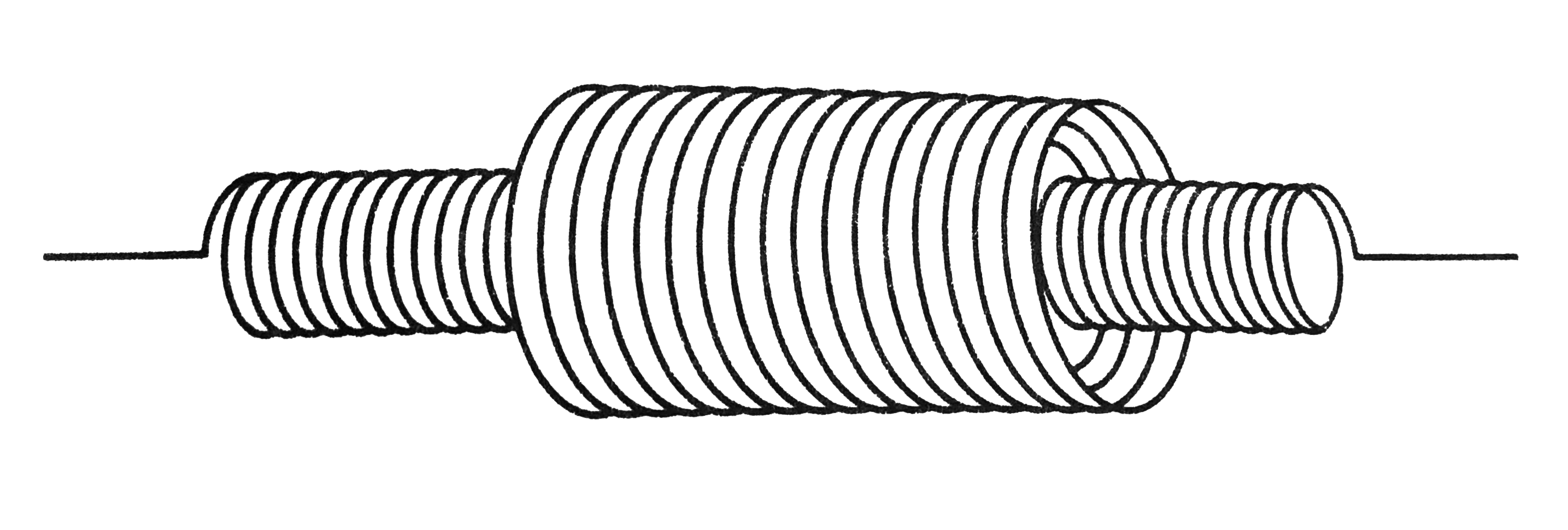
Suppose a current I is passed through the inner solenoid S1 . A magnetic field B=μ0n1i is produced inside S1 whereas the feild outside it is zero. The flux through each turn of S2 is
Biπr21=μ0n1iπr21
The total flux through all the turns in a length l of S2 is Φ=(μ0n1iπr21)n2l=(μ0n1n2πr21l)i
Thus, M=μ0n1n2πr21l.
EXAMPLE 7
A solenoid S1 is placed inside another solenoid S2 as shown in the fig. The radii of the inner and the outer solenoids are r1 and r2 respectively and the numbers of turns per unit length are n1 and n2 respectively. Consider a length I of each solenoid. Calculate the mutual inductance between them.

Suppose a current I is passed through the inner solenoid S1 . A magnetic field B=μ0n1i is produced inside S1 whereas the feild outside it is zero. The flux through each turn of S2 is
Biπr21=μ0n1iπr21
The total flux through all the turns in a length l of S2 is Φ=(μ0n1iπr21)n2l=(μ0n1n2πr21l)i
Thus, M=μ0n1n2πr21l.
EXAMPLE 8
A solenoid is connected to a battery so that a steady current flows through it. If an iron core is inserted into the solenoid, will the current increase or decrease? Explain .
When the iron core is inserted in the current carrying solenoid, the magnetic field increases due to the magnetisation of iron core and consequently the flux increases. According to Lenz's law, the emf produced must oppose this increase in flux, which can be done by making a decrease in current. So, the current will decrease.
EXAMPLE 9
Consider a metal ring kept on top of a fixed solenoid (say on a cardboard) (figure). The centre of the ring coincides with the axis of the solenoid. If the current is suddenly switched on, the metal ring jumps up. Explain.
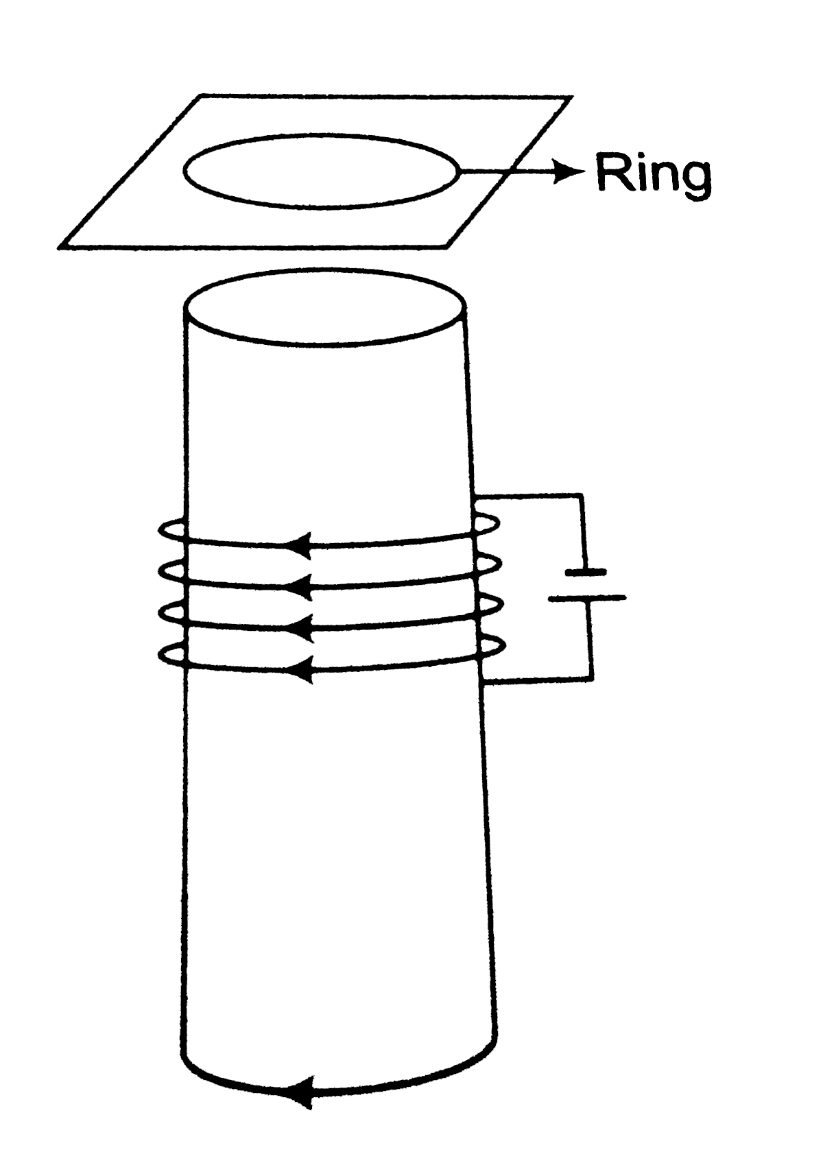
When the current is switched on, magnetic flux is linked through the ring. Thus, increases in flux takes place. According to Lenz's law, this increase in flux will be opposed and it can happen as the ring moves away from the solenoid.
This happens because the flux increases will cause a counterclockwise current (as seen from the top in the ring in figure .)i.e., opposite direction to that in the solenoid.
This makes the same sense of flow of current in the ring (when viewed from the bottom of the ring ) and solenoid forming the same magnetic pole in front of each other. Hence, they will repel each other and the ring will move upward.
EXAMPLE 9
Consider a metal ring kept on top of a fixed solenoid (say on a cardboard) (figure). The centre of the ring coincides with the axis of the solenoid. If the current is suddenly switched on, the metal ring jumps up. Explain.

When the current is switched on, magnetic flux is linked through the ring. Thus, increases in flux takes place. According to Lenz's law, this increase in flux will be opposed and it can happen as the ring moves away from the solenoid.
This happens because the flux increases will cause a counterclockwise current (as seen from the top in the ring in figure .)i.e., opposite direction to that in the solenoid.
This makes the same sense of flow of current in the ring (when viewed from the bottom of the ring ) and solenoid forming the same magnetic pole in front of each other. Hence, they will repel each other and the ring will move upward.
EXAMPLE 9
Consider a metal ring kept on top of a fixed solenoid (say on a cardboard) (figure). The centre of the ring coincides with the axis of the solenoid. If the current is suddenly switched on, the metal ring jumps up. Explain.

When the current is switched on, magnetic flux is linked through the ring. Thus, increases in flux takes place. According to Lenz's law, this increase in flux will be opposed and it can happen as the ring moves away from the solenoid.
This happens because the flux increases will cause a counterclockwise current (as seen from the top in the ring in figure .)i.e., opposite direction to that in the solenoid.
This makes the same sense of flow of current in the ring (when viewed from the bottom of the ring ) and solenoid forming the same magnetic pole in front of each other. Hence, they will repel each other and the ring will move upward.
EXAMPLE 11
Consider a metallic pipe with an inner radius of 1 cm. If a cylindrical bar magnet of radius 0.8 cm is dropped through the pipe, it takes more time to come down than it takes for a similar unmagnetised cylindrical iron bar dropped through the metallic pipe. Explain.
When cylindrical bar magnet of radius 0.8cm is dropped through the metallic pipe with an inner radius of 1cm, flux linked with the cylinder changes and consequently eddy currents are produced in the metallic pipe. According to Lenz's law. These currents will oppose the (cause) motion of the magnet.
Therefore, magent's downward acceleration will be less than the acceleration due to gravity g. On the other hand, an unmagnetised iron bar will not produce eddy currents and will fall with an acceleration due to gravity g.
Thus the magnet will take more time to come down than it takes for a similar unmagnetised cylindrical iron bar dropped through the metallic pipe.
MOTIONAL ELECTROMOTIVE FORCE
Kisi surface me ander ki taraf magnetic field hai jisme ek rod hai l length ki jisko v velocity se chala diya gaya. Aisa dekha gaya ki jab kisi rod ko magnetic field ke ander move krwate hai to us rod me bhi emf induce ho jati hai. Jaise jaise loop ander gaya loop se gujarne wali magnetic field lines badhti gai but jab loop bahar aya to magnetic field lines km bhi hoti jayegi. Loop ander jate hi flux maximum ho jayega but jab bahar flux nikl jayega to flux zero ho jayega. Jab tk loop ghumta rahega tb tk flux change hota rahega. Jab charge move karta hai to us charge pe force lagta hai.
F=q(→v×B)
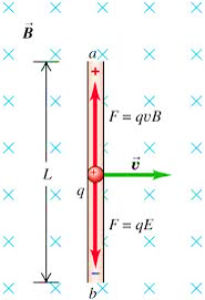
Rod aage ja ry hai to rod ke ander ka charge bhi aage jayega to is charge pe bhi force lag raha ye force positive charge me uper ki taraf lag raha hai aur negative charge me niche ki taraf force lagega to negative charge niche aane lagega aur ye rod ek battery ki tarah behave karega.
Is rod ke dono end ke bich potential difference aayega jiske karan positive se negative ki taraf electric field bhi aayega. Jaise jaise potential difference badh raha hai vaise vaise electric field ki strength badhti ja ry hai.
Jab tk charge me lagne wale electric aur magnetic force badhabar nahi ho jayega tnb tk rod ke positive charge uper aur negative charge niche ki direction me move karte rahenge.
Electric force electric field ke direction me positive end se negative end ke direction me hoga kabki magnetic force uper ke taraf electric force ke opposite direction me hoga. Ye dono force ek dusre ke equal and opposite honge. Potential difference create ho jayega aur battery form ho jayegi.
FB=Fe
q(→v×→B)=qE
E=→v×→B
Dono end ki bich induce hone wala emf
ε=E.l
ε=(→v×→B).l
Moving rod me itna hi emf (ε) hota hai.
Area time ke sath sath change ho ry hai kyuki rod aage ki taraf move kr raha hai to area bhi cover kr ry hai. Aur ye rod magnetic field line ko katti ja ry hai. Area badh raha hai flux bhi badh raha hai ϕ=B.A
ϕ=Blx
ε=Bldxdt
ε=(→v×→B).l
Inme se koi bhi do parallel ho gaye to emf induce zero ho jayega. Generally tino mutually perpendicular hote hai.
Motional EMF : An EMF (electromotive force) induced by motion relative to a magnetic field.
- Ek rod ager magnetic field me move karti hai to battery form karti hai aur EMF generate karti hai.
Induced Emf Due To Rotation
Magnetic field lete hai andar ki taraf hai. Rod ghumegi to magnetic field me circular area cover kr lega is time pe bahut sari magnetic field lines bhi cut karke jayegi. Is rod ki length ka hr part alag alag radius me ghumegi. Rod ke chhote chhote part ek definite radius me ghum rahe hai.
ε=(→v×→B).l
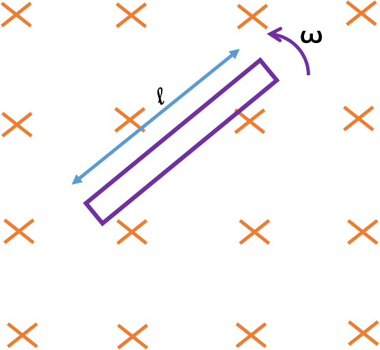
At any instant rod ke chhote se part ke tangential direction me. Rod ke sare parts ki velocity alag hogi kyuki velocity
v=rω
Radius alag alag hai isliye velocity alag alag hogi. Rod ke chote se part ke liye emf nikal ke integrate karke pure rod ka emf nikalenge. r duri pe humne elenent liya dr. Is element ki velocity hogi rω
v=rω
l=dr
∫dε=∫rωBdr
=ωB∫l0rdr
=ωB[r22]l0
ε=ωBl22
- Magnetic field ki direction change hone se induced emf ki only polarity change hogi.
OMR (One Minute Revision)
- * Faraday’s law of induction can be used to calculate the motional EMF when a change in magnetic flux is caused by a moving element in a system.
* That a moving magnetic field produces an electric field (and conversely that a moving electric field produces a magnetic field) is part of the reason electric and magnetic forces are now considered as different manifestations of the same force.
* Any change in magnetic flux induces an electromotive force (EMF) opposing that change—a process known as induction. Motion is one of the major causes of induction.
* An emf induced by motion relative to a magnetic field B is called a motional emf and is given by emf=Bℓv (B,ℓ, and v perpendicular), where ℓ is the length of the object moving at speed v relative to the field.
MOTIONAL ELECTROMOTIVE FORCE
Kisi surface me ander ki taraf magnetic field hai jisme ek rod hai l length ki jisko v velocity se chala diya gaya. Aisa dekha gaya ki jab kisi rod ko magnetic field ke ander move krwate hai to us rod me bhi emf induce ho jati hai. Jaise jaise loop ander gaya loop se gujarne wali magnetic field lines badhti gai but jab loop bahar aya to magnetic field lines km bhi hoti jayegi. Loop ander jate hi flux maximum ho jayega but jab bahar flux nikl jayega to flux zero ho jayega. Jab tk loop ghumta rahega tb tk flux change hota rahega. Jab charge move karta hai to us charge pe force lagta hai.
F=q(→v×B)

Rod aage ja ry hai to rod ke ander ka charge bhi aage jayega to is charge pe bhi force lag raha ye force positive charge me uper ki taraf lag raha hai aur negative charge me niche ki taraf force lagega to negative charge niche aane lagega aur ye rod ek battery ki tarah behave karega.
Is rod ke dono end ke bich potential difference aayega jiske karan positive se negative ki taraf electric field bhi aayega. Jaise jaise potential difference badh raha hai vaise vaise electric field ki strength badhti ja ry hai.
Jab tk charge me lagne wale electric aur magnetic force badhabar nahi ho jayega tnb tk rod ke positive charge uper aur negative charge niche ki direction me move karte rahenge.
Electric force electric field ke direction me positive end se negative end ke direction me hoga kabki magnetic force uper ke taraf electric force ke opposite direction me hoga. Ye dono force ek dusre ke equal and opposite honge. Potential difference create ho jayega aur battery form ho jayegi.
FB=Fe
q(→v×→B)=qE
E=→v×→B
Dono end ki bich induce hone wala emf
ε=E.l
ε=(→v×→B).l
Moving rod me itna hi emf (ε) hota hai.
Area time ke sath sath change ho ry hai kyuki rod aage ki taraf move kr raha hai to area bhi cover kr ry hai. Aur ye rod magnetic field line ko katti ja ry hai. Area badh raha hai flux bhi badh raha hai ϕ=B.A
ϕ=Blx
ε=Bldxdt
ε=(→v×→B).l
Inme se koi bhi do parallel ho gaye to emf induce zero ho jayega. Generally tino mutually perpendicular hote hai.
Motional EMF : An EMF (electromotive force) induced by motion relative to a magnetic field.
- Ek rod ager magnetic field me move karti hai to battery form karti hai aur EMF generate karti hai.
Induced Emf Due To Rotation
Magnetic field lete hai andar ki taraf hai. Rod ghumegi to magnetic field me circular area cover kr lega is time pe bahut sari magnetic field lines bhi cut karke jayegi. Is rod ki length ka hr part alag alag radius me ghumegi. Rod ke chhote chhote part ek definite radius me ghum rahe hai.
ε=(→v×→B).l

At any instant rod ke chhote se part ke tangential direction me. Rod ke sare parts ki velocity alag hogi kyuki velocity
v=rω
Radius alag alag hai isliye velocity alag alag hogi. Rod ke chote se part ke liye emf nikal ke integrate karke pure rod ka emf nikalenge. r duri pe humne elenent liya dr. Is element ki velocity hogi rω
v=rω
l=dr
∫dε=∫rωBdr
=ωB∫l0rdr
=ωB[r22]l0
ε=ωBl22
- Magnetic field ki direction change hone se induced emf ki only polarity change hogi.
OMR (One Minute Revision)
- * Faraday’s law of induction can be used to calculate the motional EMF when a change in magnetic flux is caused by a moving element in a system.
* That a moving magnetic field produces an electric field (and conversely that a moving electric field produces a magnetic field) is part of the reason electric and magnetic forces are now considered as different manifestations of the same force.
* Any change in magnetic flux induces an electromotive force (EMF) opposing that change—a process known as induction. Motion is one of the major causes of induction.
* An emf induced by motion relative to a magnetic field B is called a motional emf and is given by emf=Bℓv (B,ℓ, and v perpendicular), where ℓ is the length of the object moving at speed v relative to the field.
EXAMPLE 12
Figure shows planar loops of different shapes moving out of or into a region of a magnetic field which is directed normal to the plane of the loop away from the reader. Determine the direction of induced current in each loop using Lenz’s law.
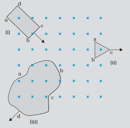
(i) The magnetic flux through the rectangular loop abcd increases, due to the motion of the loop into the region of magnetic field, The induced current must flow along the path bcdab so that it opposes the increasing flux.
(ii) Due to the outward motion, magnetic flux through the triangular loop abc decreases due to which the induced current flows along bacb, so as to oppose the change in flux.
(iii) As the magnetic flux decreases due to motion of the irregular shaped loop abcd out of the region of magnetic field, the induced current flows along cdabc, so as to oppose change in flux.
Note that there is no induced current as long as the loops are completely inside or outside the region of the magnetic field.
POINT 4
POINT 4
EXAMPLE 13
(a) A closed loop is held stationary in the magnetic field between the north and south poles of two permanent magnets held fixed. Can we hope to generate current in the loop by using very strong magnets?
(b) A closed loop moves normal to the constant electric field between the plates of a large capacitor. Is a current induced in the loop (i) when it is wholly inside the region between the capacitor plates (ii) when it is partially outside the plates of the capacitor? The electric field is normal to the plane of the loop.
(c) A rectangular loop and a circular loop are moving out of a uniform magnetic field region in the fig. to a field-free region with a constant velocity v. In which loop do you expect the induced emf to be constant during the passage out of the field region? The field is normal to the loops.

(d) Predict the polarity of the capacitor in the situation described by the fig.
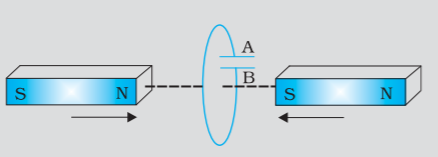
(a) No. However strong the magnet may be, current can be induced only by changing the magnetic flux through the loop.
(b) No current is induced in either case. Current can not be induced by changing the electric flux.
(c) The induced emf is expected to be constant only in the case of the rectangular loop. In the case of a circular loop, the rate of change of area of the loop during its passage out of the field region is not constant, hence induced emf will vary accordingly.
(d) The polarity of plate ‘A’ will be positive with respect to plate ‘B’ in the capacitor.
EXAMPLE 10
A conducting circular loop is placed is a uniform magnetic field B =0.20 T with its plane perpendicular to the field . Somehow, the radius of the loop starts shrinking at a constant rate of 1.0mms−1. Find the induced emf in the loop at an instant when the radius is 2 cm.
Let the radius be r at time be r at time t
The flux of the magnetic field at this instant is Ω=πr2B
Thus, dΩdt=2πrBdrdt
The induced emf when r= 2
0 cm is, therefore, ɛ=2π(2cm)(0<br>02T)(1<br>0mms−1=2<br>5μV.
MOTIONAL ELECTROMOTIVE FORCE
Kisi surface me ander ki taraf magnetic field hai jisme ek rod hai l length ki jisko v velocity se chala diya gaya. Aisa dekha gaya ki jab kisi rod ko magnetic field ke ander move krwate hai to us rod me bhi emf induce ho jati hai. Jaise jaise loop ander gaya loop se gujarne wali magnetic field lines badhti gai but jab loop bahar aya to magnetic field lines km bhi hoti jayegi. Loop ander jate hi flux maximum ho jayega but jab bahar flux nikl jayega to flux zero ho jayega. Jab tk loop ghumta rahega tb tk flux change hota rahega. Jab charge move karta hai to us charge pe force lagta hai.
F=q(→v×B)

Rod aage ja ry hai to rod ke ander ka charge bhi aage jayega to is charge pe bhi force lag raha ye force positive charge me uper ki taraf lag raha hai aur negative charge me niche ki taraf force lagega to negative charge niche aane lagega aur ye rod ek battery ki tarah behave karega.
Is rod ke dono end ke bich potential difference aayega jiske karan positive se negative ki taraf electric field bhi aayega. Jaise jaise potential difference badh raha hai vaise vaise electric field ki strength badhti ja ry hai.
Jab tk charge me lagne wale electric aur magnetic force badhabar nahi ho jayega tnb tk rod ke positive charge uper aur negative charge niche ki direction me move karte rahenge.
Electric force electric field ke direction me positive end se negative end ke direction me hoga kabki magnetic force uper ke taraf electric force ke opposite direction me hoga. Ye dono force ek dusre ke equal and opposite honge. Potential difference create ho jayega aur battery form ho jayegi.
FB=Fe
q(→v×→B)=qE
E=→v×→B
Dono end ki bich induce hone wala emf
ε=E.l
ε=(→v×→B).l
Moving rod me itna hi emf (ε) hota hai.
Area time ke sath sath change ho ry hai kyuki rod aage ki taraf move kr raha hai to area bhi cover kr ry hai. Aur ye rod magnetic field line ko katti ja ry hai. Area badh raha hai flux bhi badh raha hai ϕ=B.A
ϕ=Blx
ε=Bldxdt
ε=(→v×→B).l
Inme se koi bhi do parallel ho gaye to emf induce zero ho jayega. Generally tino mutually perpendicular hote hai.
Motional EMF : An EMF (electromotive force) induced by motion relative to a magnetic field.
- Ek rod ager magnetic field me move karti hai to battery form karti hai aur EMF generate karti hai.
Induced Emf Due To Rotation
Magnetic field lete hai andar ki taraf hai. Rod ghumegi to magnetic field me circular area cover kr lega is time pe bahut sari magnetic field lines bhi cut karke jayegi. Is rod ki length ka hr part alag alag radius me ghumegi. Rod ke chhote chhote part ek definite radius me ghum rahe hai.
ε=(→v×→B).l

At any instant rod ke chhote se part ke tangential direction me. Rod ke sare parts ki velocity alag hogi kyuki velocity
v=rω
Radius alag alag hai isliye velocity alag alag hogi. Rod ke chote se part ke liye emf nikal ke integrate karke pure rod ka emf nikalenge. r duri pe humne elenent liya dr. Is element ki velocity hogi rω
v=rω
l=dr
∫dε=∫rωBdr
=ωB∫l0rdr
=ωB[r22]l0
ε=ωBl22
- Magnetic field ki direction change hone se induced emf ki only polarity change hogi.
OMR (One Minute Revision)
- * Faraday’s law of induction can be used to calculate the motional EMF when a change in magnetic flux is caused by a moving element in a system.
* That a moving magnetic field produces an electric field (and conversely that a moving electric field produces a magnetic field) is part of the reason electric and magnetic forces are now considered as different manifestations of the same force.
* Any change in magnetic flux induces an electromotive force (EMF) opposing that change—a process known as induction. Motion is one of the major causes of induction.
* An emf induced by motion relative to a magnetic field B is called a motional emf and is given by emf=Bℓv (B,ℓ, and v perpendicular), where ℓ is the length of the object moving at speed v relative to the field.
EXAMPLE 11
A conducting circular loop of face are 2.5X10⁻³m2 is placed perpendicular to a magnetic field which varies as B=(0.20T)sin[(50πs−1)t]. (a)Find the chargej flowing through any cross- section during the time t=0 to t=40 ms.(b) If the resistance of the loop is 10Ω, find the thermal energy developed in the loop in this period.
The face area of the loop is A=2<br>5X10⁻⁵m2andthemag≠ticfieldchan≥sasB=B0sinωtwhereB0=0<br>20Tandω=50πs−1<br>Theresistanceofthel∞pisR=10Ω<br>Thefluxthroughthel∞pattimetisPhi =B_0 A sin omega t<br>Theemf∈ducedisverepsilon =-(dPhi)/(dt) =- B_0 Aomega cos omega t
the current is i= (varepsilon)/(R)=-(B_0 A omega)(R) cos omega t =- i_0 cos omega t
The current changes sinusoidally with the time period T=2πω=2π50πs−1=40ms<br>(a)Thechar≥flow∈gthroughanycrosssection∈40ms∈Q=int_0^T idt=-i_0 int_0^T cos omega t dt=−i0ω[sinωt]0=0
(b)The thermal energy produced in 40 ms is H=∫T0i2Rdt=i20R∫T0cos2ωtdt =i20R2∫T0(1+cos2ωt)dt =i20R2[t+sin2ωt2ω]T0 =(i_0^2 RT)/(2) =(B_0^2 A^2 omega^2)/(2R^2) R((2pi)/(omega)) = (piB_0^2A^2 omega)/(R) =(pi X(0
20T)^2 X(2
5 X10^(-3)m^2)2 X(50pi s^(-1))/(10 Omega) =1
25X10^(-5) J
POINT 4
EXAMPLE 12
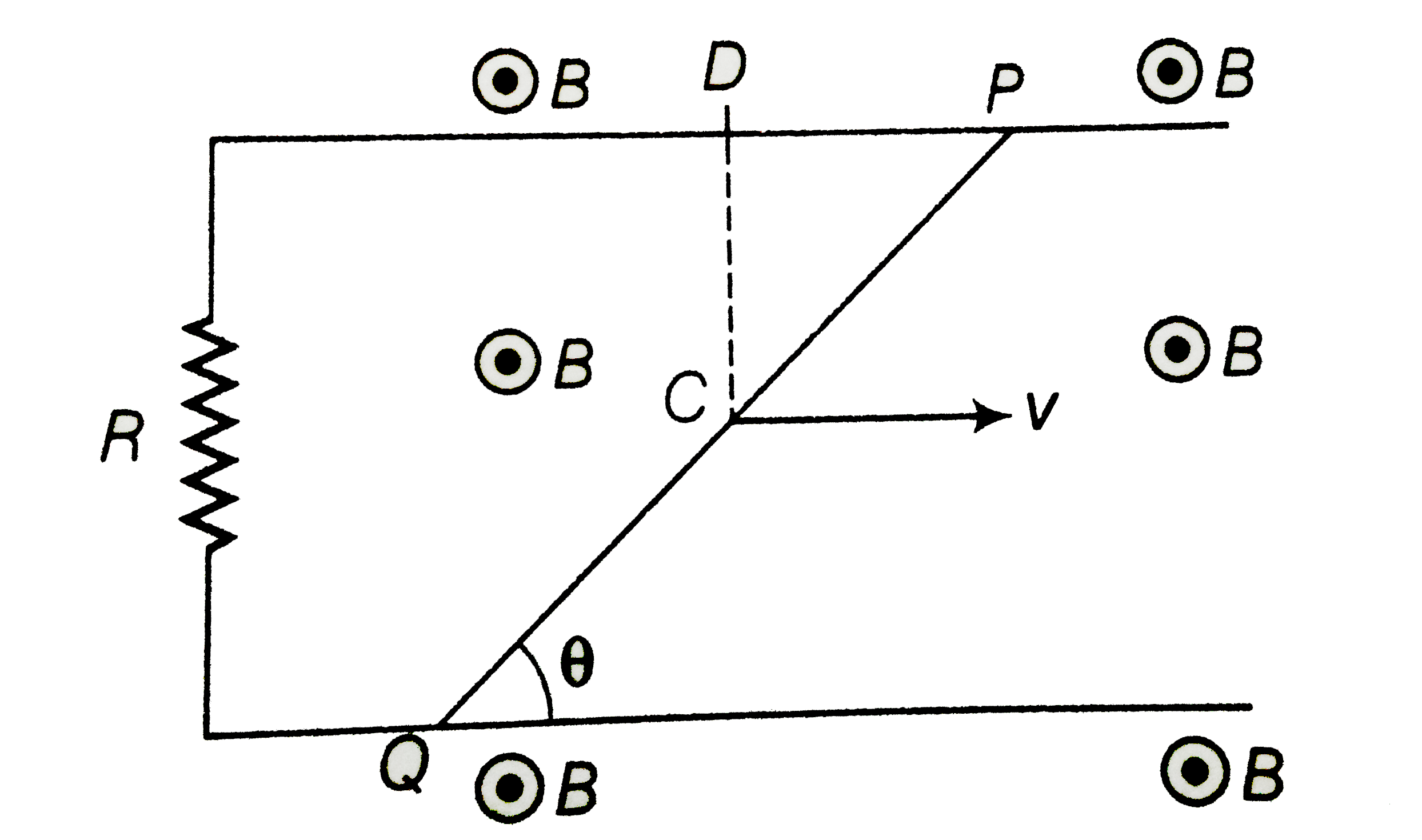
Find the current in the wire for the configuration shown in figure. Wire PQ has negligible resistance, B, the magnetic field is coming out of the paper. θ is a fixed angle made by PQ travelling smoothly over two conducting parallel wires separated by a distance d.
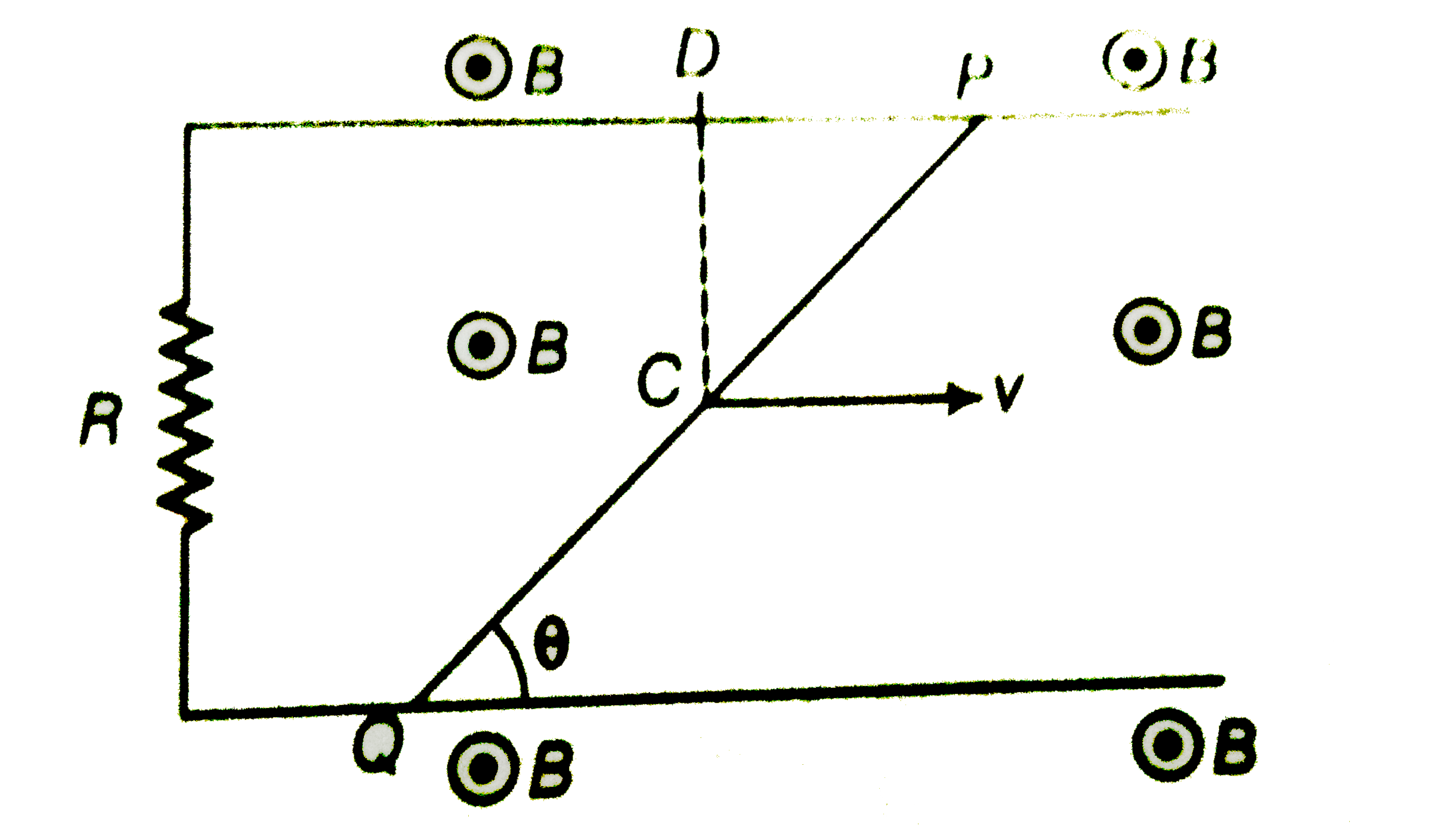
The motional electric field E along the dotted line CD(∧ to both v and B and along VxB)=Vb
Therefore, the motional emf along PQ=(length PQ)x(Field along PQ)
(length PQ)×(vBsinθ)
=(dsinθ)×(vBsinθ)=vBd
EXAMPLE 12
Find the current in the wire for the configuration shown in figure. Wire PQ has negligible resistance, B, the magnetic field is coming out of the paper. θ is a fixed angle made by PQ travelling smoothly over two conducting parallel wires separated by a distance d.

The motional electric field E along the dotted line CD(∧ to both v and B and along VxB)=Vb
Therefore, the motional emf along PQ=(length PQ)x(Field along PQ)
(length PQ)×(vBsinθ)
=(dsinθ)×(vBsinθ)=vBd

EXAMPLE 14
A long solenoid S has n turns per meter, with diameter a. At the centre of this coil, we place a smaller coil of N turns and diameter b (where blta). If the current in the solenoid increases linearly, with time, what is the induced emf appearing in the smaller coil. Plot showing nature of variation in emf, if current varies as a function of mt2+c.
Magnetic field due to a solenoid S,B=μ0nl where signs are as usual .
Magnetic flux in smaller coil ϕ=NBA where A=πb2
Applying Faraday's law of EMI, we have
So, e=dϕdt=−ddt(NBA)
=−Nπb2d(B)dt
where, B=μ0Ni
=−Nπb2μ0ndldt
=−Nnπμ0b2ddt(mt2+c)=−μ0Nnπb22mt
Since, current varies as a function of mt2+C.
e=−μ0Nnπb22mt
EXAMPLE 13
A magnetic field B=B0sin(ωt)ˆk covers a large region where a wire AB slides smoothly over two parallel conductors separated by a distance d (figure). The wires are in the x−y plane. The wire AB (of length d) has resistance R and the parallel wires have negligible resistance. If AB is moving with velocity v, what is the current in the circuit. What is the force needed to keep the wire moving at constant velocity ?
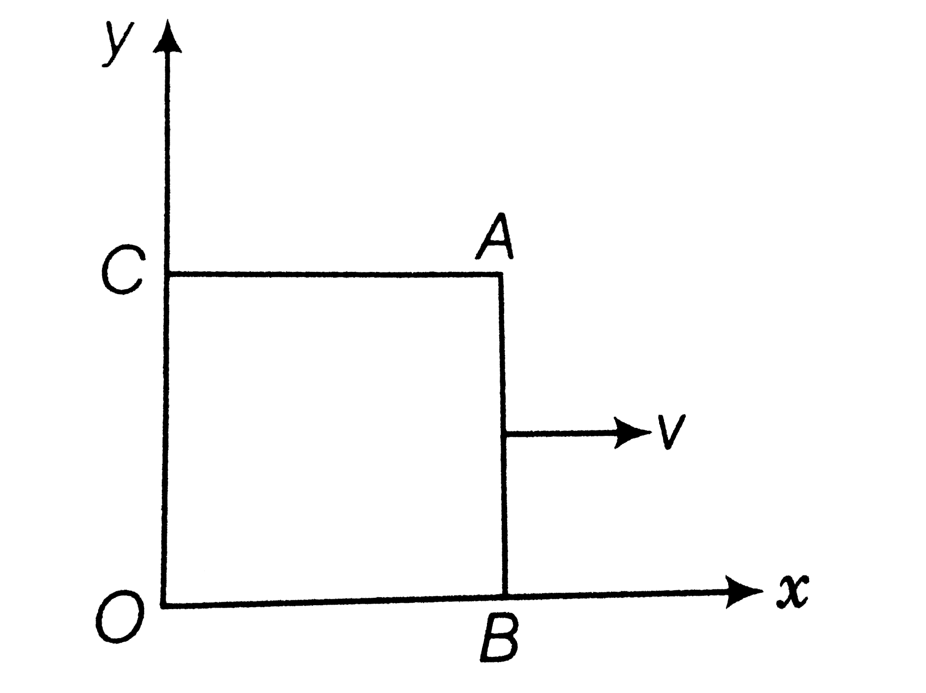
Let us assume that the parallel wires at are y=0 i.e., along x-axis and y=d. At t=0, AB has x=0, i.e, along y-axis and moves with a velocity v. Let at time t, wire is at x(t)=vt.
Now, the motional emf across AB is =(B0sinωt)vd(−ˆj)
emf due to change in field (along) OBAC)
=−B0ωcosωtx(t)d
Total emf in the circuit =emf due to change in field (along OBAC)+the motional emf across AB
=−B0d[ωxcos(ωt)+vsin(ωt)]
Electric current in clockwise direction is given by
=B0dR(ωxcosωt+vsinωt)
The force acting on the conductor is given by F=ilBsin90∘=ilB
Substituting the values, we have
Force needed along i=B0dR(ωxcosωt+vsinωt)×dxxB0sinωt
=B20d2R(ωxcosωt+vsinωt)sinωt
This is the required expression for force.
EXAMPLE 13
A magnetic field B=B0sin(ωt)ˆk covers a large region where a wire AB slides smoothly over two parallel conductors separated by a distance d (figure). The wires are in the x−y plane. The wire AB (of length d) has resistance R and the parallel wires have negligible resistance. If AB is moving with velocity v, what is the current in the circuit. What is the force needed to keep the wire moving at constant velocity ?

Let us assume that the parallel wires at are y=0 i.e., along x-axis and y=d. At t=0, AB has x=0, i.e, along y-axis and moves with a velocity v. Let at time t, wire is at x(t)=vt.
Now, the motional emf across AB is =(B0sinωt)vd(−ˆj)
emf due to change in field (along) OBAC)
=−B0ωcosωtx(t)d
Total emf in the circuit =emf due to change in field (along OBAC)+the motional emf across AB
=−B0d[ωxcos(ωt)+vsin(ωt)]
Electric current in clockwise direction is given by
=B0dR(ωxcosωt+vsinωt)
The force acting on the conductor is given by F=ilBsin90∘=ilB
Substituting the values, we have
Force needed along i=B0dR(ωxcosωt+vsinωt)×dxxB0sinωt
=B20d2R(ωxcosωt+vsinωt)sinωt
This is the required expression for force.
EXAMPLE 15
A metallic ring of mass m and radius l (ring horizontal ) is falling under gravity in a region having a magnetic field. If z is the vertical direction, the z-component of magnetic field is Bz=B0(1+λ).If R is the resistance of the ring and if the ring falls with a velocity v, find the energy lost in the resistance. If the ring has reached a constant velocity,use the conservation of energy to determine v in terms of m, B, λ and acceleration due to gravity g.
The magnetic flux linked with the metallic ring of mass m and radius l falling under gravity in a region having a magnetic field whose z-component of magnetic field is Bz=B0(1+λ) is
ϕ−Bz(πl2)=B0(1+λ)(πl2)
Applying Faraday's law of EMI, we have emf induced given by dϕdt = rate of change of flux also, by Ohm's law
B0(πl2)λdzdt=lR
On rearranging the terms, we have l=πl2B0λR
Energy lost/second l2R=(πl2λ)2B20V2R
This must come from rate of change in PE=mg(dz)dt=mgv
Thus , mgv=π2λB20v2Ror v=mgR(πl2λB0)2
This is the required expression of velocity.
EXAMPLE 14
A conducting wire XY of mass M and negligible resistance slides smoothly on two parallel conducting wires as shown in figure. The closed circuit has a resistance R due to AC. AB and CD are perfect conductors. There is a magnetic field B=B(t)ˆk
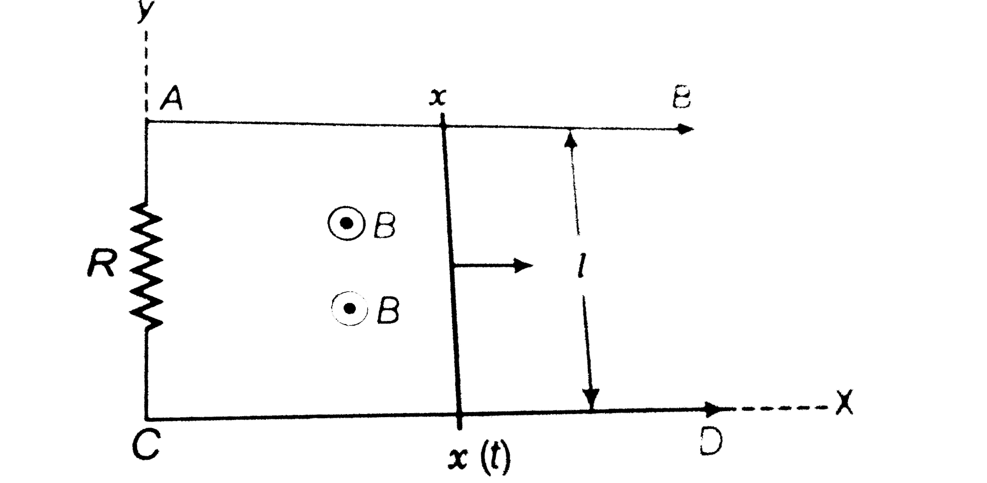
Let us assume that the parallel wiers at are y=0, i.e., along x-axis and y-l, At=0, XY has x=0 i.e., along y-axis.
(i) Let the wire be at x=x(t) at time t.
The magnetic flux linked with the loop is given by
θ=B.A=BAcos0=BA
at any instant t
Magnetic flux = B(t)(l×x(t))
Total emf in the circuit= emf due to change in field (along XYAC) + the motional emf across XY
E=−dϕdt=−(dB(t)dtlx(t)−B(t)lv(t) [second term due to motional emf]
Electric current in clockwise direction is given by
I=1RE
The force acting on the conductor is given by F=ilBsin90∘=ilB
Substituting the values, we have
Force =IB(t)R[−dB(t)dtIx(t)−B(t)Iv(t)]ˆi
Applying Newton's second law of motion,
md2xdt2=−I2B(t)RdBdtx(t)−I2B2(t)Rdxdt
Which is the required equation.
ii) If B is independent of time i.e., B=Constant
Or dBdt=0
Substituting the above value in Eq(i), we have
d2xdt2+I2B2mRdxdt=0
dvdt+I2B2mRV=0
Integrating using variable separable form of differential equation, we have
V=Aexp(−I2B2tmR)
Applying given conditions
at t=0v=u0
v(t)=u0exp(−I2B2t/mR)
This is the required equation,
Since the power consumption is given by P=I2R
Here,
I2R=B2I2V2(t)R2×R
=B2I2Ru20exp(−2I2B2tImR)
Now, energy consumed in time interval dt is given by energy consumed =Pdt=I2Rdt
Therefore, total energy consumed in time t
=∫t0I2Rdt=B2I2Rμ20mR2I2B2[1−e−(l2B2t/mr)
m2u20−m2v2(t)
= decrease in kinetic energy.
This proves that the decrease in kinetic energy of XY equals the heat lost in R.
EXAMPLE 14
A conducting wire XY of mass M and negligible resistance slides smoothly on two parallel conducting wires as shown in figure. The closed circuit has a resistance R due to AC. AB and CD are perfect conductors. There is a magnetic field B=B(t)ˆk

Let us assume that the parallel wiers at are y=0, i.e., along x-axis and y-l, At=0, XY has x=0 i.e., along y-axis.
(i) Let the wire be at x=x(t) at time t.
The magnetic flux linked with the loop is given by
θ=B.A=BAcos0=BA
at any instant t
Magnetic flux = B(t)(l×x(t))
Total emf in the circuit= emf due to change in field (along XYAC) + the motional emf across XY
E=−dϕdt=−(dB(t)dtlx(t)−B(t)lv(t) [second term due to motional emf]
Electric current in clockwise direction is given by
I=1RE
The force acting on the conductor is given by F=ilBsin90∘=ilB
Substituting the values, we have
Force =IB(t)R[−dB(t)dtIx(t)−B(t)Iv(t)]ˆi
Applying Newton's second law of motion,
md2xdt2=−I2B(t)RdBdtx(t)−I2B2(t)Rdxdt
Which is the required equation.
ii) If B is independent of time i.e., B=Constant
Or dBdt=0
Substituting the above value in Eq(i), we have
d2xdt2+I2B2mRdxdt=0
dvdt+I2B2mRV=0
Integrating using variable separable form of differential equation, we have
V=Aexp(−I2B2tmR)
Applying given conditions
at t=0v=u0
v(t)=u0exp(−I2B2t/mR)
This is the required equation,
Since the power consumption is given by P=I2R
Here,
I2R=B2I2V2(t)R2×R
=B2I2Ru20exp(−2I2B2tImR)
Now, energy consumed in time interval dt is given by energy consumed =Pdt=I2Rdt
Therefore, total energy consumed in time t
=∫t0I2Rdt=B2I2Rμ20mR2I2B2[1−e−(l2B2t/mr)
m2u20−m2v2(t)
= decrease in kinetic energy.
This proves that the decrease in kinetic energy of XY equals the heat lost in R.
EXAMPLE 16
Find the current in the wire for the configuration shown in figure. Wire PQ has negligible resistance, B, the magnetic field is coming out of the paper. θ is a fixed angle made by PQ travelling smoothly over two conducting parallel wires separated by a distance d.

The motional electric field E along the dotted line CD(∧ to both v and B and along VxB)=Vb
Therefore, the motional emf along PQ=(length PQ)x(Field along PQ)
(length PQ)×(vBsinθ)
=(dsinθ)×(vBsinθ)=vBd

ENERGY CONSIDERATION
Hume pata hai ki Force aur energy kya hai. Kisi bhi body pr force apply krne ke liye energy ki jarurat hoti hai. Force aur energy ke beech ek link hoti hai, ye link energy consideration provide krti hai. Energy consideration ke concept se hum prove kr skte hai ki motional emf conservation of energy ke according valid ya correct hai ya nahi. Motional emf me energy consideration ke principles ko apply krne ke liye, hume Lenz’s law aur law of conservation of energy pr focus krna hoga. Lenz’s law conservation of energy se agree krta hai.
Hum consider krte hai ki ek conductor uniform magnetic field me move kr raha hai aur uska time magnetic field pr depend nahi kr raha hai. Figure me aap dekhenge rod PQ constant velocity vse move kr raha hai.
Kya rod ka motion directly hua? Nahi. Humne rod ko v jitni velocity di magnetic field me move krane ke liye aur uske liye work done krna para aur isme kuch energy use hua. Is energy ko mechanical energy kahte hai. Mechanical energy se jo power consume hoti hai usse mechanical power kahte hain. Jab mechanical power electrical power ke equal ho jata hai to iska mtlb hai energy conservation hua hai.
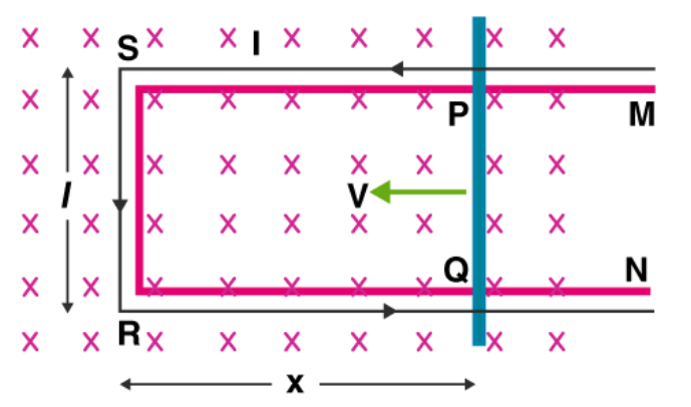
Mechanical Power, P=F×v, where F is the force and v is the velocity.
Suppose, r rod ka resistance hai, so according to Ohm’s law,
I=Vr
Since voltage is emf, so I=ϵr
ϵ is the motional emf, so
The work done in moving the charge from P to Q is, W=qvBl
Since emf is the work done per unit charge, ε=Wq
ε=Blv
F=BIL, Since I=Bvℓ
So F=BLBvℓr
F=B2l2vr
Mechanical power, Pm=F×v
=B2ℓ2vr×v
Pm=B2ℓ2v2r
Electrical Power, Pe=V×I
=BVℓ×Bvℓr
Pe=B2v2ℓ2r
P_m= P_e
EDDY CURRENTS
Humne induced current padha. Jab bhi coil aur magnet me koi relative motion hota hai toh coil ke across ek emf set up ho jata hai aur vo emf induced emf kahlata hai. Iske karan coil ke ander jo current milta hai, usse induced current kahte hai. Eddy currents bhi induced currents hote hain. Jab bulk piece of conductor me induced current produce hoti hai, magnetic flux jo bulk piece of conductor se associated hain, unke change ke karan, usse eddy currents kahte hain.Eddy currents are loops of electrical current induced within conductors by a changing magnetic field in the conductor according to Faraday’s law of induction. Eddy currents flow in closed loops within conductors, in planes perpendicular to the magnetic field.
Suppose, hamare paas ek conductor piece hai aur usse paas ek magnet lekr aae ya dur lekr jaye, ya koi magnetic field me se hum conductor piece ko field se bahar nikal de achanak ya field ke ander le aae, phir jo conductor piece se associated magnetic flux hain vo change hone lagenge aur conductor piece ke ander induced currents set up ho jayengi. In induced currents ka hi naam hota hai, eddy currents.
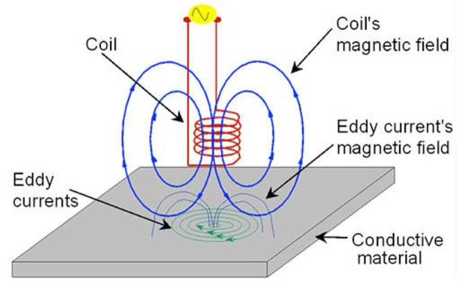
Eddies ka mtlb hota hai bhavar. Jab pani me hum stone dalte hai toh jo gol gol bhavar uthte hain, unhe eddy kehte hain. Issi se eddy currents naam para hai kyunki pani aur currents ke flow patterns ek jaise lgte hain. Conductor me currents circular form me flow hote hain.
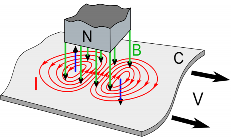
Niche diye image me aap dekhenge ki ek copper plate ko pendulum ke jaisa swing krte hain ek strong magnet ke do poles ke beech. North poles se magnetic fields nikalkr south pole me jayengi. Initially, copper plate ko stable hone me jyada time lagega jab wo magnetic field me nahi hoga aur jab magnetic field ke influence me hoga tab stable hone me km time lagega. Aisa isliye hoga kyunki magnet ke presence me ek force hai jo copper plate ke oscillation ko oppose kr raha hai. Isse electromagnetic damping kehte hain. Damping ka mtlb hota hai amplitude bahut slow ho jana.
Damping plays an important role in controlling the motion of an object. It is an opposition offered to the motion of an object.
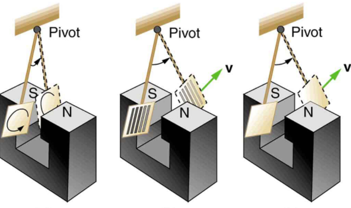
Initially flux zero tha, jab copper plate magnetic field me aaega to uska flux ϕ ho jayega. Jab flux me increment hoga tab copper plate ke electrons circulate krna start krenge copper plate ke ander. Flux ke change ke karan, copper plate me eddy current induce hoga aur current ke magnetic moments is change ko oppose krenge. Magnetic field me copper plate ke aane ke baad speed km ho jayegi. Copper plate magetic field se bhr jane ka kosish aur uska flux ϕ se zero hone ka kosish krega. Phir se induced current ke magnetic moments, according to Lenz's law, is change ko oppose krenge aur usse bhr jane se rokenge.
Jab copper plate ke area ko km kr denge to eddy current ka flow bhi km ho jayega. Pendulum plate jisme holes aur slots hote hain wo electromagnetic damping ko reduce krte hain aur plate jyada freely move kr pata hai.
- 1. Directions of eddy currents are opposite when the plate swings into the region between the poles and when it swings out of the region.
2. Magnetic moments of the induced currents depend upon the area enclosed by the currents (m = IA).
HOW TO MINIMIZE EDDY CURRENTS
Ager hum kisi coil ke area ko km kr de toh eddy currents minimize ho jayengi, heating effect km ho jayega.
Do coils ke beech ek insulating material jaise ki lacquer, lagane se eddy currents km ho jayega. Insulating material lagane se ek current ki effect dushre coil pr nahi pregi iska mtlb dushre ka phle se koi mtlb nahi hoga aur overall energy reduced rahegi.
1. The plane of the laminations must be arranged parallel to the magnetic field, so that they cut across the eddy current paths.
2. This fact is helpful in reducing eddy currents in the metallic cores of transformers, electric motors and other such devices in which a coil is to be wound over metallic core.
APPLICATIONS OF EDDY CURRENTS
Electromagnetic Damping: Kuch galvanometer me fixed core hote jo nonmagnetic material se bane hote hain. Jab coil oscillate krta hai to eddy currents jo coil me generate hote hain, wo coil ke motion ko oppose krte hain aur coil jldi rest pr aa jata hai.Induction Furnace: Induction furnace high temperature produce krne ke liye aur constituent metals ko melt krke alloy ke preparation me use hote hain. Alternating current jiska frequency high hota hai use coil se pass karate hain. Coil jo metals melt krne hote hain, unko surround karta hai. Metals me eddy currents produce hote hai jo high temperature produce krte hain jinse metals melt ho jate hain.
Magnetic Braking in trains: Rails ke upr strong electromagnets hote hain. Jab electromagnets activate hote hain, to eddy currents jo rails me induce hote hain wo train ke motion ko oppose krte hain aur braking effect smooth hota hai.
Electric power meters: Electric power meters me eddy currents ke karan metal disc rotate karta hai. Magnetic field metal disc me electric current produce krte hain.
INDUCTANCE
Self-inductance
Ek loop hai jisme flux change ho ya current change ho to isi loop me flux ya current me change ki wajah se emf induce ho jaye use self emf induced hota hai ise self inductance kahte hai.Koi bhi loop jisme current I hai isme jo flux hai wo current ke proportional hoga. Proportionality hatane se constant lete hai L, ise hi kehte hai self inductance
Φ∝i
Φ=Li
L=ϕi wb/A
BecauseL constant hai isliye L, ϕ ya i pr depend nahi karta hai.
Ek loop se guzarne wala flux hai ϕ aur ager N no. of turns hai to total ϕ =Nϕ
Hence, Nϕ∝i
Nϕ=Li
ε=−ddtΦtotal
ε=−ddt(NΦ)
ε=−ddt(Li)
ε=−Ldidt
Back emf - Self induced emf ko back emf isliye kehte hai kyuki jaise jaise hi current badhaya jata hai vaise vaise hi opposite direction me emf induce hota jata hai. Ye emf opposite direction me induced ho raha hai kyuki Lenz's law ko follow karta hai aur back emf kehlata hai.
Solenoid (Self Inductance)
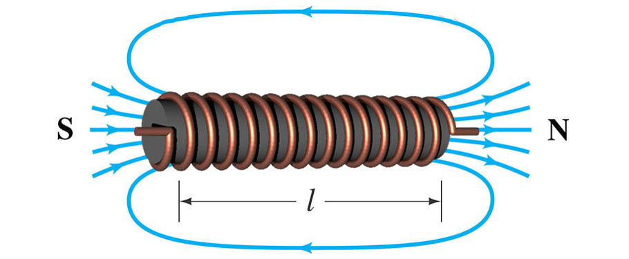
Ek solenoid jiska length l aur area A hai. No. of turns /length=n and Total no. of turns=N=nl
Ager is solenoid mecurrent i ja rahi to ϕ=B.A
ϕ=μ0ni.A (ek loop se gujarne wale flux)
ϕ=μ0ni.A.N (N=nl) (total flux)
ϕ=μ0ni.A.(nl)
ϕ=μ0n2i.A.l
ϕ=μ0n2i.v
L=ϕi=μ0n2i.vi
L=μ0n2v
Solenoid ke per unit volume ka inductance Lv=μ0n2 =constant
Energy Stotomato in Inductor
ε=−Ldidt
P=εi
P=Ldidti
Power is energy consumed per unit time
dEdt=Ldidti
∫E0dE=∫i0Lidi
E=Li22=12Li2
Ye inductor me stored energy hai.
Mutual inductance
Ager khud me current me change hone se dusre loop me flux me change ho aur emf induce ho ise mutual inductance kahte hai.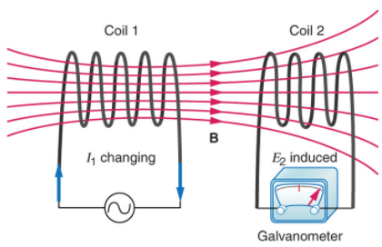
Ek coil me battery ke help se current change karne se dusre coil ki emf me change ho raha hai.
Solenoid (Mutual Inductance)
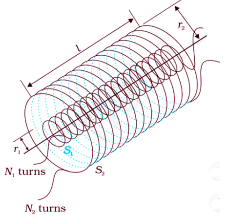
Do solenoide hai small solenoid S1 and big solenoid S2
S1 total no. of turns =N1
No. of turns per unit length=n1
Radius =r1
Current =i1
Bigger solenoid S2 me
total no. of turns =N2
No. of turns per unit length =n2
Radius =r2
Current =i2
Mutual induction se ager big solenoid me current change karte hai to iska magnetic field change ho jayega jisse chhote wale solenoid ke surrounding magnetic field time ke sath change ho raha hai. B change ho raha to flux bhi change ho raha hai means small solenoid me flux me change ki wajah se emf induce hoga.
Ager small solenoid me current change karte hai to iske l length ke volume me magnetic field change ho jayega jisse bigger solenoid ke us hisse me magnetic field time ke sath change ho raha hai jo volume smaller solenoid ne cover kiya hai. Magnetic field B change ho raha to flux bhi change ho raha hai means bigger solenoid me flux me change ki wajah se emf induce hoga.
Hume yaha pr mutual inductance calculate karna hai.
ϕ1∝i2
ϕ1=M12i2
M12= mutual inductance of 1 with respect to 2
M12=ϕ1i2
ϕ1= smaller solenoid se gujarne wala flux jo bigger solenoid me current ki wajah se hai.
Φ1=μ0n2i2πr21
Mutual inductance in total no. of turns
M12=N1ϕ1i2
M12=N1μ0n2i2πr21i2
M12=N1μ0n2πr21
M12=n1lμ0n2πr21
M12=μ0n1n2(πr21l)
M21= mutual inductance of S2 with respect to S1
ϕ2∝i1
ϕ2=M21i1
M21=ϕ2i1
Φ2= bigger solenoid se gujarne wala flux jo smaller solenoid me current ki wajah se hai.
Φ2=μ0n1i1πr21
Mutual inductance in total no. of turns
M21=N2ϕ2i1
M21=N2μ0n1i1πr21i1
M21=N2μ0n1πr21
M21=n2lμ0n1πr21
M21=μ0n1n2(πr21l)
M12=M21
- Ek solenoid ka dusre solenoid ke respect me Mutual inductance equal hai.
OMR (One Minute Revision)
- * Mutual inductance is the effect of two devices in inducing emfs in each other. A change in current ΔI1Δt in one induces an emf, emf2 in the second: EMF2=−MΔI1Δt, where M is defined to be the mutual inductance between the two devices.
* Self-inductance is the effect of the device inducing emf in itself.
* A device that exhibits significant self-inductance is called an inductor, and the EMF induced in it by a change in current through it is EMF=−LΔIΔt.
* Input EMF that powers a motor can be opposed by the motor’s self-generated EMF, called the back EMF of the motor.
* If motional EMF can cause a current loop in the conductor, the current is called an eddy current.
* Eddy currents can produce significant drag, called magnetic damping, on the motion involved.
* In the case of electronics, inductance is the property of a conductor by which a change in current in the conductor creates a voltage in both the conductor itself, called self-inductance, and any nearby conductors, called mutual inductance.
* From Lenz’s law, a changing electric current through a circuit that has inductance induces a proportional voltage which opposes the change in current.
* Mutual inductance is illustrated by. A change in the current I1 in one device, coil 1 in the figure, induces an emf2 in the other. We express this in equation form as emf2=−MΔI1Δt. M is the same for the reverse process.
* Self-inductance is the effect of Faraday’s law of induction of a device on itself. The induced emf is related to the physical geometry of the device and the rate of change of current given by emf=−L(ΔI)/(Δt)
* A device that exhibits significant self-inductance is called an inductor, and given the symbol in.
* Any rotating coil will have an induced emf—in motors, this is called back emf, since it opposes the emf input to the motor.
Applications of Electromagnetic Induction
1. Hard drives utilize magnetic induction to read/write information.2. Other applications of magnetic induction can be found in graphics tablets, electric and hybrid vehicles, and in transcranial magnetic stimulation.
ENERGY CONSIDERATION
Hume pata hai ki Force aur energy kya hai. Kisi bhi body pr force apply krne ke liye energy ki jarurat hoti hai. Force aur energy ke beech ek link hoti hai, ye link energy consideration provide krti hai. Energy consideration ke concept se hum prove kr skte hai ki motional emf conservation of energy ke according valid ya correct hai ya nahi. Motional emf me energy consideration ke principles ko apply krne ke liye, hume Lenz’s law aur law of conservation of energy pr focus krna hoga. Lenz’s law conservation of energy se agree krta hai.
Hum consider krte hai ki ek conductor uniform magnetic field me move kr raha hai aur uska time magnetic field pr depend nahi kr raha hai. Figure me aap dekhenge rod PQ constant velocity vse move kr raha hai.
Kya rod ka motion directly hua? Nahi. Humne rod ko v jitni velocity di magnetic field me move krane ke liye aur uske liye work done krna para aur isme kuch energy use hua. Is energy ko mechanical energy kahte hai. Mechanical energy se jo power consume hoti hai usse mechanical power kahte hain. Jab mechanical power electrical power ke equal ho jata hai to iska mtlb hai energy conservation hua hai.

Mechanical Power, P=F×v, where F is the force and v is the velocity.
Suppose, r rod ka resistance hai, so according to Ohm’s law,
I=Vr
Since voltage is emf, so I=ϵr
ϵ is the motional emf, so
The work done in moving the charge from P to Q is, W=qvBl
Since emf is the work done per unit charge, ε=Wq
ε=Blv
F=BIL, Since I=Bvℓ
So F=BLBvℓr
F=B2l2vr
Mechanical power, Pm=F×v
=B2ℓ2vr×v
Pm=B2ℓ2v2r
Electrical Power, Pe=V×I
=BVℓ×Bvℓr
Pe=B2v2ℓ2r
P_m= P_e
EDDY CURRENTS
Humne induced current padha. Jab bhi coil aur magnet me koi relative motion hota hai toh coil ke across ek emf set up ho jata hai aur vo emf induced emf kahlata hai. Iske karan coil ke ander jo current milta hai, usse induced current kahte hai. Eddy currents bhi induced currents hote hain. Jab bulk piece of conductor me induced current produce hoti hai, magnetic flux jo bulk piece of conductor se associated hain, unke change ke karan, usse eddy currents kahte hain.Eddy currents are loops of electrical current induced within conductors by a changing magnetic field in the conductor according to Faraday’s law of induction. Eddy currents flow in closed loops within conductors, in planes perpendicular to the magnetic field.
Suppose, hamare paas ek conductor piece hai aur usse paas ek magnet lekr aae ya dur lekr jaye, ya koi magnetic field me se hum conductor piece ko field se bahar nikal de achanak ya field ke ander le aae, phir jo conductor piece se associated magnetic flux hain vo change hone lagenge aur conductor piece ke ander induced currents set up ho jayengi. In induced currents ka hi naam hota hai, eddy currents.

Eddies ka mtlb hota hai bhavar. Jab pani me hum stone dalte hai toh jo gol gol bhavar uthte hain, unhe eddy kehte hain. Issi se eddy currents naam para hai kyunki pani aur currents ke flow patterns ek jaise lgte hain. Conductor me currents circular form me flow hote hain.

Niche diye image me aap dekhenge ki ek copper plate ko pendulum ke jaisa swing krte hain ek strong magnet ke do poles ke beech. North poles se magnetic fields nikalkr south pole me jayengi. Initially, copper plate ko stable hone me jyada time lagega jab wo magnetic field me nahi hoga aur jab magnetic field ke influence me hoga tab stable hone me km time lagega. Aisa isliye hoga kyunki magnet ke presence me ek force hai jo copper plate ke oscillation ko oppose kr raha hai. Isse electromagnetic damping kehte hain. Damping ka mtlb hota hai amplitude bahut slow ho jana.
Damping plays an important role in controlling the motion of an object. It is an opposition offered to the motion of an object.

Initially flux zero tha, jab copper plate magnetic field me aaega to uska flux ϕ ho jayega. Jab flux me increment hoga tab copper plate ke electrons circulate krna start krenge copper plate ke ander. Flux ke change ke karan, copper plate me eddy current induce hoga aur current ke magnetic moments is change ko oppose krenge. Magnetic field me copper plate ke aane ke baad speed km ho jayegi. Copper plate magetic field se bhr jane ka kosish aur uska flux ϕ se zero hone ka kosish krega. Phir se induced current ke magnetic moments, according to Lenz's law, is change ko oppose krenge aur usse bhr jane se rokenge.
Jab copper plate ke area ko km kr denge to eddy current ka flow bhi km ho jayega. Pendulum plate jisme holes aur slots hote hain wo electromagnetic damping ko reduce krte hain aur plate jyada freely move kr pata hai.
- 1. Directions of eddy currents are opposite when the plate swings into the region between the poles and when it swings out of the region.
2. Magnetic moments of the induced currents depend upon the area enclosed by the currents (m = IA).
HOW TO MINIMIZE EDDY CURRENTS
Ager hum kisi coil ke area ko km kr de toh eddy currents minimize ho jayengi, heating effect km ho jayega.
Do coils ke beech ek insulating material jaise ki lacquer, lagane se eddy currents km ho jayega. Insulating material lagane se ek current ki effect dushre coil pr nahi pregi iska mtlb dushre ka phle se koi mtlb nahi hoga aur overall energy reduced rahegi.
1. The plane of the laminations must be arranged parallel to the magnetic field, so that they cut across the eddy current paths.
2. This fact is helpful in reducing eddy currents in the metallic cores of transformers, electric motors and other such devices in which a coil is to be wound over metallic core.
APPLICATIONS OF EDDY CURRENTS
Electromagnetic Damping: Kuch galvanometer me fixed core hote jo nonmagnetic material se bane hote hain. Jab coil oscillate krta hai to eddy currents jo coil me generate hote hain, wo coil ke motion ko oppose krte hain aur coil jldi rest pr aa jata hai.Induction Furnace: Induction furnace high temperature produce krne ke liye aur constituent metals ko melt krke alloy ke preparation me use hote hain. Alternating current jiska frequency high hota hai use coil se pass karate hain. Coil jo metals melt krne hote hain, unko surround karta hai. Metals me eddy currents produce hote hai jo high temperature produce krte hain jinse metals melt ho jate hain.
Magnetic Braking in trains: Rails ke upr strong electromagnets hote hain. Jab electromagnets activate hote hain, to eddy currents jo rails me induce hote hain wo train ke motion ko oppose krte hain aur braking effect smooth hota hai.
Electric power meters: Electric power meters me eddy currents ke karan metal disc rotate karta hai. Magnetic field metal disc me electric current produce krte hain.
INDUCTANCE
Self-inductance
Ek loop hai jisme flux change ho ya current change ho to isi loop me flux ya current me change ki wajah se emf induce ho jaye use self emf induced hota hai ise self inductance kahte hai.Koi bhi loop jisme current I hai isme jo flux hai wo current ke proportional hoga. Proportionality hatane se constant lete hai L, ise hi kehte hai self inductance
Φ∝i
Φ=Li
L=ϕi wb/A
BecauseL constant hai isliye L, ϕ ya i pr depend nahi karta hai.
Ek loop se guzarne wala flux hai ϕ aur ager N no. of turns hai to total ϕ =Nϕ
Hence, Nϕ∝i
Nϕ=Li
ε=−ddtΦtotal
ε=−ddt(NΦ)
ε=−ddt(Li)
ε=−Ldidt
Back emf - Self induced emf ko back emf isliye kehte hai kyuki jaise jaise hi current badhaya jata hai vaise vaise hi opposite direction me emf induce hota jata hai. Ye emf opposite direction me induced ho raha hai kyuki Lenz's law ko follow karta hai aur back emf kehlata hai.
Solenoid (Self Inductance)

Ek solenoid jiska length l aur area A hai. No. of turns /length=n and Total no. of turns=N=nl
Ager is solenoid mecurrent i ja rahi to ϕ=B.A
ϕ=μ0ni.A (ek loop se gujarne wale flux)
ϕ=μ0ni.A.N (N=nl) (total flux)
ϕ=μ0ni.A.(nl)
ϕ=μ0n2i.A.l
ϕ=μ0n2i.v
L=ϕi=μ0n2i.vi
L=μ0n2v
Solenoid ke per unit volume ka inductance Lv=μ0n2 =constant
Energy Stotomato in Inductor
ε=−Ldidt
P=εi
P=Ldidti
Power is energy consumed per unit time
dEdt=Ldidti
∫E0dE=∫i0Lidi
E=Li22=12Li2
Ye inductor me stored energy hai.
Mutual inductance
Ager khud me current me change hone se dusre loop me flux me change ho aur emf induce ho ise mutual inductance kahte hai.
Ek coil me battery ke help se current change karne se dusre coil ki emf me change ho raha hai.
Solenoid (Mutual Inductance)

Do solenoide hai small solenoid S1 and big solenoid S2
S1 total no. of turns =N1
No. of turns per unit length=n1
Radius =r1
Current =i1
Bigger solenoid S2 me
total no. of turns =N2
No. of turns per unit length =n2
Radius =r2
Current =i2
Mutual induction se ager big solenoid me current change karte hai to iska magnetic field change ho jayega jisse chhote wale solenoid ke surrounding magnetic field time ke sath change ho raha hai. B change ho raha to flux bhi change ho raha hai means small solenoid me flux me change ki wajah se emf induce hoga.
Ager small solenoid me current change karte hai to iske l length ke volume me magnetic field change ho jayega jisse bigger solenoid ke us hisse me magnetic field time ke sath change ho raha hai jo volume smaller solenoid ne cover kiya hai. Magnetic field B change ho raha to flux bhi change ho raha hai means bigger solenoid me flux me change ki wajah se emf induce hoga.
Hume yaha pr mutual inductance calculate karna hai.
ϕ1∝i2
ϕ1=M12i2
M12= mutual inductance of 1 with respect to 2
M12=ϕ1i2
ϕ1= smaller solenoid se gujarne wala flux jo bigger solenoid me current ki wajah se hai.
Φ1=μ0n2i2πr21
Mutual inductance in total no. of turns
M12=N1ϕ1i2
M12=N1μ0n2i2πr21i2
M12=N1μ0n2πr21
M12=n1lμ0n2πr21
M12=μ0n1n2(πr21l)
M21= mutual inductance of S2 with respect to S1
ϕ2∝i1
ϕ2=M21i1
M21=ϕ2i1
Φ2= bigger solenoid se gujarne wala flux jo smaller solenoid me current ki wajah se hai.
Φ2=μ0n1i1πr21
Mutual inductance in total no. of turns
M21=N2ϕ2i1
M21=N2μ0n1i1πr21i1
M21=N2μ0n1πr21
M21=n2lμ0n1πr21
M21=μ0n1n2(πr21l)
M12=M21
- Ek solenoid ka dusre solenoid ke respect me Mutual inductance equal hai.
OMR (One Minute Revision)
- * Mutual inductance is the effect of two devices in inducing emfs in each other. A change in current ΔI1Δt in one induces an emf, emf2 in the second: EMF2=−MΔI1Δt, where M is defined to be the mutual inductance between the two devices.
* Self-inductance is the effect of the device inducing emf in itself.
* A device that exhibits significant self-inductance is called an inductor, and the EMF induced in it by a change in current through it is EMF=−LΔIΔt.
* Input EMF that powers a motor can be opposed by the motor’s self-generated EMF, called the back EMF of the motor.
* If motional EMF can cause a current loop in the conductor, the current is called an eddy current.
* Eddy currents can produce significant drag, called magnetic damping, on the motion involved.
* In the case of electronics, inductance is the property of a conductor by which a change in current in the conductor creates a voltage in both the conductor itself, called self-inductance, and any nearby conductors, called mutual inductance.
* From Lenz’s law, a changing electric current through a circuit that has inductance induces a proportional voltage which opposes the change in current.
* Mutual inductance is illustrated by. A change in the current I1 in one device, coil 1 in the figure, induces an emf2 in the other. We express this in equation form as emf2=−MΔI1Δt. M is the same for the reverse process.
* Self-inductance is the effect of Faraday’s law of induction of a device on itself. The induced emf is related to the physical geometry of the device and the rate of change of current given by emf=−L(ΔI)/(Δt)
* A device that exhibits significant self-inductance is called an inductor, and given the symbol in.
* Any rotating coil will have an induced emf—in motors, this is called back emf, since it opposes the emf input to the motor.
Applications of Electromagnetic Induction
1. Hard drives utilize magnetic induction to read/write information.2. Other applications of magnetic induction can be found in graphics tablets, electric and hybrid vehicles, and in transcranial magnetic stimulation.
EXAMPLE 17
A magnetic field B=B0sin(ωt)ˆk covers a large region where a wire AB slides smoothly over two parallel conductors separated by a distance d (figure). The wires are in the x−y plane. The wire AB (of length d) has resistance R and the parallel wires have negligible resistance. If AB is moving with velocity v, what is the current in the circuit. What is the force needed to keep the wire moving at constant velocity ?

Let us assume that the parallel wires at are y=0 i.e., along x-axis and y=d. At t=0, AB has x=0, i.e, along y-axis and moves with a velocity v. Let at time t, wire is at x(t)=vt.
Now, the motional emf across AB is =(B0sinωt)vd(−ˆj)
emf due to change in field (along) OBAC)
=−B0ωcosωtx(t)d
Total emf in the circuit =emf due to change in field (along OBAC)+the motional emf across AB
=−B0d[ωxcos(ωt)+vsin(ωt)]
Electric current in clockwise direction is given by
=B0dR(ωxcosωt+vsinωt)
The force acting on the conductor is given by F=ilBsin90∘=ilB
Substituting the values, we have
Force needed along i=B0dR(ωxcosωt+vsinωt)×dxxB0sinωt
=B20d2R(ωxcosωt+vsinωt)sinωt
This is the required expression for force.
POINT 5
POINT 5
EXAMPLE 18
A conducting wire XY of mass M and negligible resistance slides smoothly on two parallel conducting wires as shown in figure. The closed circuit has a resistance R due to AC. AB and CD are perfect conductors. There is a magnetic field B=B(t)ˆk

Let us assume that the parallel wiers at are y=0, i.e., along x-axis and y-l, At=0, XY has x=0 i.e., along y-axis.
(i) Let the wire be at x=x(t) at time t.
The magnetic flux linked with the loop is given by
θ=B.A=BAcos0=BA
at any instant t
Magnetic flux = B(t)(l×x(t))
Total emf in the circuit= emf due to change in field (along XYAC) + the motional emf across XY
E=−dϕdt=−(dB(t)dtlx(t)−B(t)lv(t) [second term due to motional emf]
Electric current in clockwise direction is given by
I=1RE
The force acting on the conductor is given by F=ilBsin90∘=ilB
Substituting the values, we have
Force =IB(t)R[−dB(t)dtIx(t)−B(t)Iv(t)]ˆi
Applying Newton's second law of motion,
md2xdt2=−I2B(t)RdBdtx(t)−I2B2(t)Rdxdt
Which is the required equation.
ii) If B is independent of time i.e., B=Constant
Or dBdt=0
Substituting the above value in Eq(i), we have
d2xdt2+I2B2mRdxdt=0
dvdt+I2B2mRV=0
Integrating using variable separable form of differential equation, we have
V=Aexp(−I2B2tmR)
Applying given conditions
at t=0v=u0
v(t)=u0exp(−I2B2t/mR)
This is the required equation,
Since the power consumption is given by P=I2R
Here,
I2R=B2I2V2(t)R2×R
=B2I2Ru20exp(−2I2B2tImR)
Now, energy consumed in time interval dt is given by energy consumed =Pdt=I2Rdt
Therefore, total energy consumed in time t
=∫t0I2Rdt=B2I2Rμ20mR2I2B2[1−e−(l2B2t/mr)
m2u20−m2v2(t)
= decrease in kinetic energy.
This proves that the decrease in kinetic energy of XY equals the heat lost in R.
EXAMPLE 15
Shows a wire of length l which can slide on a U- shaped rail of negligible resistance. The resistance of the wire is R. The wire is pulled ot the right with a constant speed v. Draw an equivalent circuit diagram representing the induced emf by a battery. Find the current in the wire usingj this diagram.
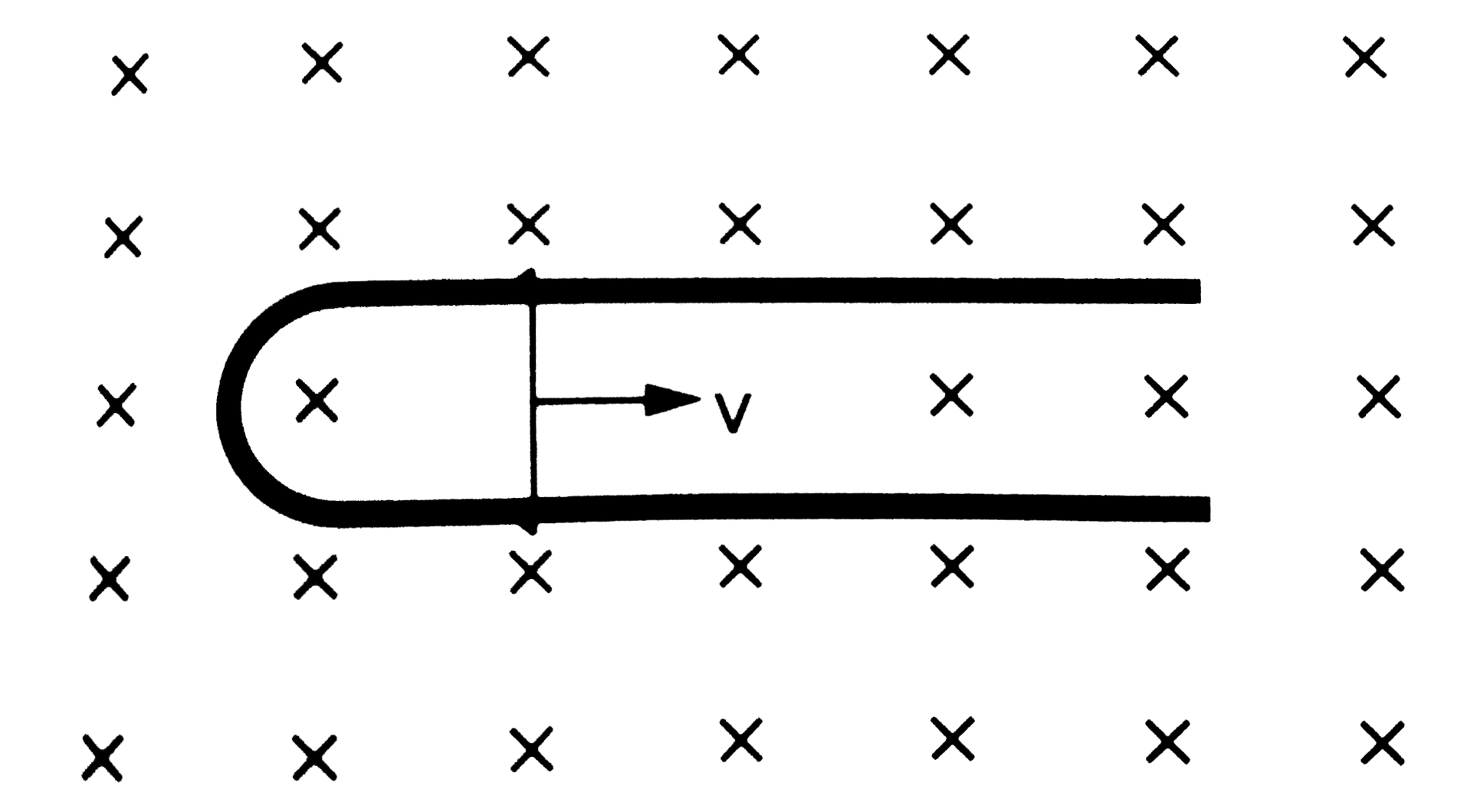
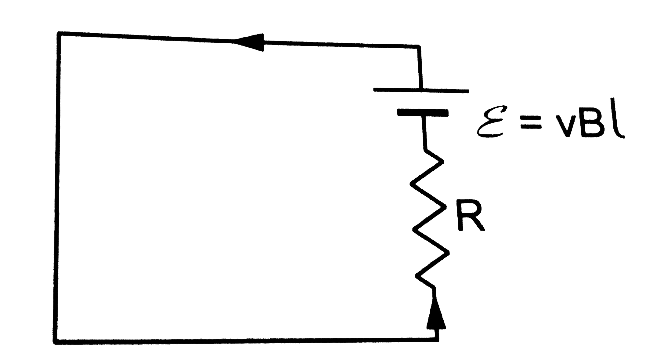
The emf is induced due to the moving wire
The magnitude of theis emf is ε=vBl
As the wire moves towards right, the force vec qv X vecB on a positive charge acts in the upward direction in the figure
The positve terminal of the equivalent battery appears upwards
The resistance of the wire acts as the internal resistance of the equivalent battery
The equivalent circuit is drawn i fingure(38
W8b
) The current in the circuit is , from Ohm's law, i=εR=vBlR
It is in the upward direction along the wire
EXAMPLE 15
Shows a wire of length l which can slide on a U- shaped rail of negligible resistance. The resistance of the wire is R. The wire is pulled ot the right with a constant speed v. Draw an equivalent circuit diagram representing the induced emf by a battery. Find the current in the wire usingj this diagram.


The emf is induced due to the moving wire
The magnitude of theis emf is ε=vBl
As the wire moves towards right, the force vec qv X vecB on a positive charge acts in the upward direction in the figure
The positve terminal of the equivalent battery appears upwards
The resistance of the wire acts as the internal resistance of the equivalent battery
The equivalent circuit is drawn i fingure(38
W8b
) The current in the circuit is , from Ohm's law, i=εR=vBlR
It is in the upward direction along the wire
EXAMPLE 19
ODBAC is a fixed rectangular conductor of negligible resistance (C0 is not connected) and 0P is a conductor which clockwise with an angular velocity ω (figure). The entire system is in a uniform magnetic field B whose direction is along the normal to the surface of the rectangular conductor ABDC. The conductor OP is in electric contact with ABDC. The rotating conductor has a resistance of λ per unit length. Find the current in the rotating conductor, as it rotates by 180∘.
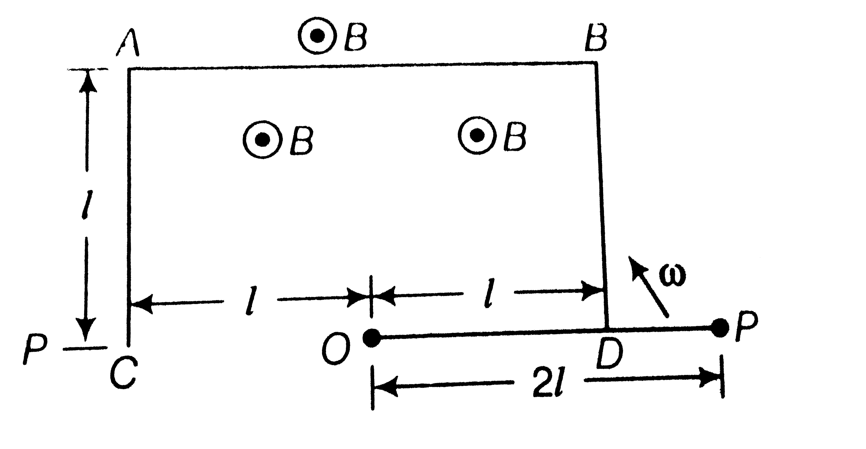
Let us consider the position of rotating conductor at time interval
t=0t=π4ω(orT/8)

The rod OP will make contact with the side BD. Let the length OQ of the contact at sometime t such that 0<t<π4ω or 0<t<T8 be x. The flux through the area ODQ is
ϕ=B12QD×OD=B12ltanθ×l
=12Bi2tanθ, where θ=ωt
Applying Faraday's law of EMI,
Thus, the current is I=εR where R is the resistance of the rod in contact.
Where, R∝λ
R=λx=λlcosωt
∴I=12Bl2ωλlsec2ωtcosωt=Blω2λcosωt
let the length OQ of the contact at some time t such that π4ω<t<3π4π or Tx<t<3T8 be x. The rod is in contact with the side AB. The flux through the area OQBD is
ϕ=(l2+12l2tanθ)B
Where, θ=ωt
Thus, the magnitude of emf generated in the loop is
ε=dϕdt=12Bl2ωsec2ωttan2ωt
The current is I=εR=ελx=εsinωtλl=12Blωλsinωt
Similarly for 3ω4ω<t<πω or 3T8<t<T2 the rod will be in touch with AC.
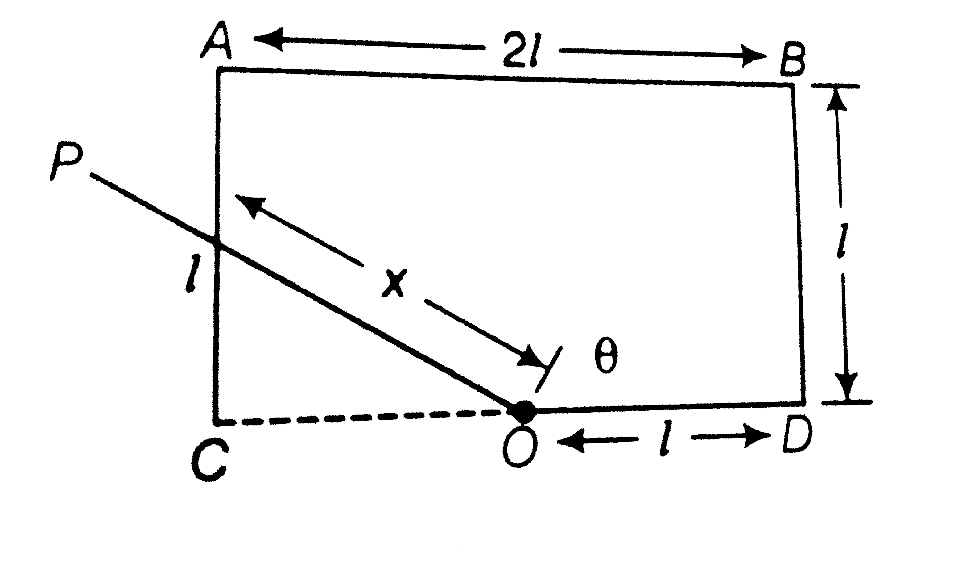
The flux through OQABD is given by
ϕ=(2l2−l22tanωt)B
And the magnitude of emf generated in loop is given by
ε=dϕdt=Bωl2sec2ωt2tan2ωt
l=εR=ελx=12Blωλsinωt
These are the required expressions.
EXAMPLE 16
Two concentric circular coils, one of small radius r_1 and the other of large radius r_2, such that r1 << r2, are placed co-axially with centres coinciding. Obtain the mutual inductance of the arrangement.
Let a current I_2 flow through the outer circular coil. The field at the centre of the coil is B2=μ0I22r2. Since the other co-axially placed coil has a very small radius, B_2 may be considered constant over its cross-sectional area. Hence,
Φ1=πr2_1B2
=(μ0πr2_12r2)I2
=M12I2
Thus, M12=μ0πr2_1
M12=M21 =(μ0πr2_12r2)I2
Note that we calculated M12 from an approximate value of Φ1, assuming the magnetic field B2 to be uniform over the area πr2_1 . However, we can accept this value because r1⟨r2.
EXAMPLE 20
Consider an infinitely long wire carrying a current I(t), with dIdt=λ= constant. Find the current produced in the rectangular loop of wire ABCD if its resistance is R (figure).
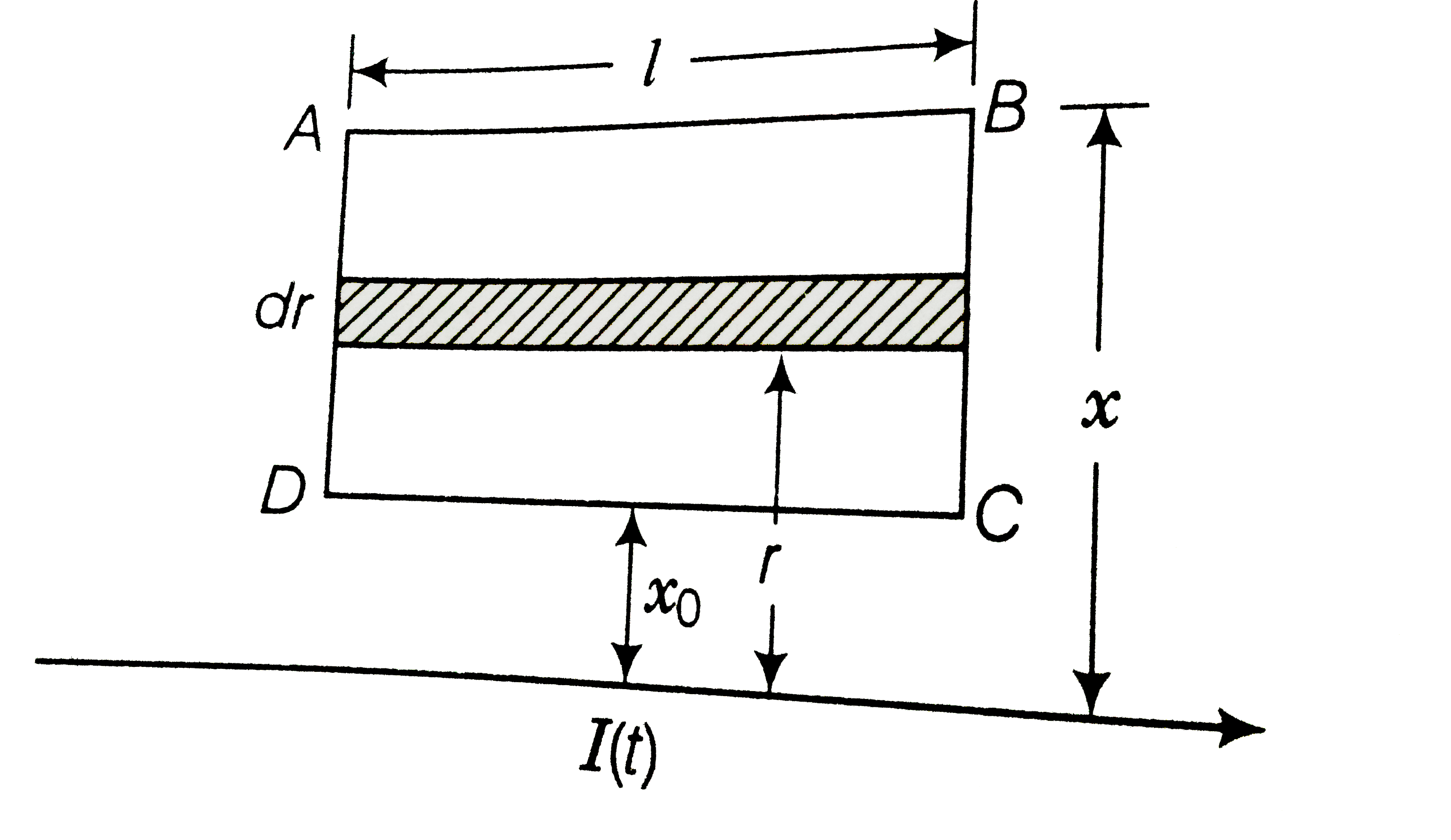
Let us consider a strip of length l and width dr at a distance r from infinite long current carrying wire. The magnetic field at strip due to current carrying wire is given by Field B(r)=μ0I2πr (out of paper)
Total flux through the loop is Flux =μ0I2πl∫xxOdrr=μoI2πInxxo......(i)
The emf induced can be obtained by differentiating the eq. (i) wrt t and then applying Ohm's law
εR=I
We have, induced current =1Rdϕdt=εR=μ0I2πλRInxx0
(∵dIdt=λ).
A.C. GENERATOR
A.C. generator ka mtlb "Alternating Current generator" hai. A.C. generator ka use hum factory ya ghar pr karte hain jab mains se electric supply nahi hoti hai, as an alternative source of electricity. A.C. generator alternating current produce karta hai jo apna direction continuously reverse karta hai. A.C. generator ko alternator bhi kahte hain. The current which changes direction after equal intervals of time, is called an alternating current (abbreviated as AC). This device is called an AC generator.
PRINCIPLE
A.C. generator mechanical energy ko electrical energy me convert karta hai.Generator me coil magnetic field me rotate karta hai. Is rotation ke karan magnetic flux jo coil se link hota hai vo change karta hai aur isliye e.m.f. (electromotive force) coil ke ends ke beech me induce hota hai. Generator load containing external circuit me source of current ke tarah act karta jab usse coil ke dono ends ke beech join karte hain.
CONSTRUCTION AND MAIN PARTS of A.C. GENERATOR
The main parts of an a.c. generator are:1. A horseshoe electromagnet NS,
2. The armature coil ABCD,
3. The slip rings S1, S2, and
4. The brushes B1, B2.
Horseshoe electromagnet NS: Ye strong magnet hai N aur S poles ka.
Armature coil ABCD: Soft iron core ka ka arms ABCD hai jisko armature coil kehte hai. Ispr insulated wire wound hain with many turns. Ye coil rapidly magnetic field me rotate hota hai poles of field magnet ke beech, by an axle fixed to it.
Slip rings S1 and S2: Slip ring cylindrical circular pipe hota hai. Do coaxial metallic rings S1 aur S2 hote hain jo coil ke along rotate hota hai. Jab coil rotate krta hai, to slip rings bhi rotate krte hain. Coil ka ek end slip ring S1 se connected hota hai aur dusra end slip ring S2 se connected hota hai.
Dono ring stationary brush ke against slip karta hai.
Brushes B1 and B2: Do carbon brushes B1 aur B2 slip rings S1 aur S2 ke against gently press hote hain. Brushes electrical connection ke jaisa act krte hai slip rings aur electrical component ya load ke beech. Brushes ke dusre end generator ke terminal ke tarah act karte hain jiske across load containing external circuit connected hote hain. Brushes B1 aur B2 coil aur slip rings ke along slip nahi karte hain.
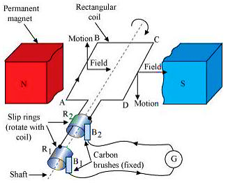
WORKING OF A.C. GENERATOR
Jab armature poles of field magnet ke beech rotate karta hai to armature se linked magnetic flux continuously change karta hai. Is karan armature me e.m.f. (electromotive force) induce hota hai jiske karan electric current produce hota hai.Jab armature clockwise direction me rotate karta hai, tab Flemming’s right hand rule ko apply karke, external circuit me induced current ko find kr sakte hain. Induced current opposite direction me flow hota hai jiske karan galvanometer me deflection ka direction left me hota hai.
Thus, we see that the direction of induced current changes in the external circuit after every half revolution of the armature, i.e., after the armature has turned through an angle of 180° from its initial position. Hence, the induced current is alternating in nature.
WORKING FORMULA
Jab coil constant angular speed ω se rotate krta hai to magnetic field vector B aur coil ka area vector A ke beech ka angle θ at any instant t is θ=ωt (assuming θ = 0º at t = 0).Iske karan jo coil ka area magnetic field me hain vo time ke saath km ho jata hai. Flux at any time t is (ΦB)=BAcosθ
=BAcosωt
Faraday’s law se, ε=−NdΦBdt
=−NBAddt(cosωt)
So, emf ka instantaneous value, ε=NBAωsinωt
Yaha pr NBAω emf ka maximum value hai, ye tab hota hai jab sinωt=±1. Ager hum NBAω ko ε0 denote kre, to ε=ε0sinωt.
Sine function ka value +1 aur –1 ke beech hota hai isliye emf ka sign ya polarity time ke saath change hota hai.
Since ω=2πν, so ε=ε0sin2πνt
Yaha pr v generator ke coil ke revolution ka frequency hai.
1. Emf has its extremum value when θ = 90º or θ=270º, as the change of flux is greatest at these points.
2. The direction of the current changes periodically and therefore the current is called alternating current (ac).
A.C. GENERATOR
A.C. generator ka mtlb "Alternating Current generator" hai. A.C. generator ka use hum factory ya ghar pr karte hain jab mains se electric supply nahi hoti hai, as an alternative source of electricity. A.C. generator alternating current produce karta hai jo apna direction continuously reverse karta hai. A.C. generator ko alternator bhi kahte hain. The current which changes direction after equal intervals of time, is called an alternating current (abbreviated as AC). This device is called an AC generator.
PRINCIPLE
A.C. generator mechanical energy ko electrical energy me convert karta hai.Generator me coil magnetic field me rotate karta hai. Is rotation ke karan magnetic flux jo coil se link hota hai vo change karta hai aur isliye e.m.f. (electromotive force) coil ke ends ke beech me induce hota hai. Generator load containing external circuit me source of current ke tarah act karta jab usse coil ke dono ends ke beech join karte hain.

CONSTRUCTION AND MAIN PARTS of A.C. GENERATOR
The main parts of an a.c. generator are:1. A horseshoe electromagnet NS,
2. The armature coil ABCD,
3. The slip rings S1, S2, and
4. The brushes B1, B2.
Horseshoe electromagnet NS: Ye strong magnet hai N aur S poles ka.
Armature coil ABCD: Soft iron core ka ka arms ABCD hai jisko armature coil kehte hai. Ispr insulated wire wound hain with many turns. Ye coil rapidly magnetic field me rotate hota hai poles of field magnet ke beech, by an axle fixed to it.
Slip rings S1 and S2: Slip ring cylindrical circular pipe hota hai. Do coaxial metallic rings S1 aur S2 hote hain jo coil ke along rotate hota hai. Jab coil rotate krta hai, to slip rings bhi rotate krte hain. Coil ka ek end slip ring S1 se connected hota hai aur dusra end slip ring S2 se connected hota hai.
Dono ring stationary brush ke against slip karta hai.
Brushes B1 and B2: Do carbon brushes B1 aur B2 slip rings S1 aur S2 ke against gently press hote hain. Brushes electrical connection ke jaisa act krte hai slip rings aur electrical component ya load ke beech. Brushes ke dusre end generator ke terminal ke tarah act karte hain jiske across load containing external circuit connected hote hain. Brushes B1 aur B2 coil aur slip rings ke along slip nahi karte hain.

WORKING OF A.C. GENERATOR
Jab armature poles of field magnet ke beech rotate karta hai to armature se linked magnetic flux continuously change karta hai. Is karan armature me e.m.f. (electromotive force) induce hota hai jiske karan electric current produce hota hai.Jab armature clockwise direction me rotate karta hai, tab Flemming’s right hand rule ko apply karke, external circuit me induced current ko find kr sakte hain. Induced current opposite direction me flow hota hai jiske karan galvanometer me deflection ka direction left me hota hai.
Thus, we see that the direction of induced current changes in the external circuit after every half revolution of the armature, i.e., after the armature has turned through an angle of 180° from its initial position. Hence, the induced current is alternating in nature.
WORKING FORMULA
Jab coil constant angular speed ω se rotate krta hai to magnetic field vector B aur coil ka area vector A ke beech ka angle θ at any instant t is θ=ωt (assuming θ = 0º at t = 0).Iske karan jo coil ka area magnetic field me hain vo time ke saath km ho jata hai. Flux at any time t is (ΦB)=BAcosθ
=BAcosωt
Faraday’s law se, ε=−NdΦBdt
=−NBAddt(cosωt)
So, emf ka instantaneous value, ε=NBAωsinωt
Yaha pr NBAω emf ka maximum value hai, ye tab hota hai jab sinωt=±1. Ager hum NBAω ko ε0 denote kre, to ε=ε0sinωt.
Sine function ka value +1 aur –1 ke beech hota hai isliye emf ka sign ya polarity time ke saath change hota hai.
Since ω=2πν, so ε=ε0sin2πνt
Yaha pr v generator ke coil ke revolution ka frequency hai.
1. Emf has its extremum value when θ=90º or θ=270º, as the change of flux is greatest at these points.
2. The direction of the current changes periodically and therefore the current is called alternating current (ac).
EXAMPLE 21
A rod of mass m and resistance R slides smoothly over two parallel perfectly conducting wires kept sloping at an angle θ with respect to the horizontal (figure). The circuit is closed through a perfect conductor at the top. There is a constant magnetic field B along the vertical direction. If the rod is initially at rest, find the velocity of the rod as a function of time.
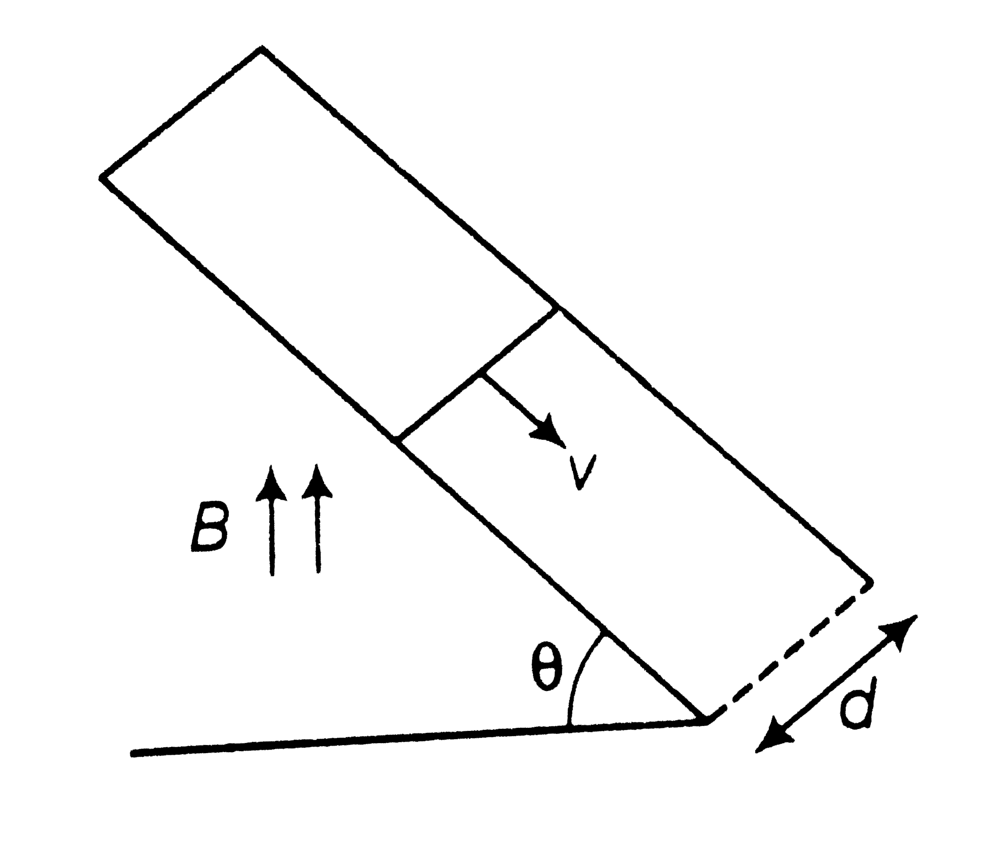
Here, the component of magnetic field perpendicular the plane =Bcosθ Now, the conductor moves with speed v perpendicular to Bcosθ component of magnetic field. This causes motional emf across two ends of rod, which is given by =v(Bcosθ)d
This makes flow of induced current i=v(Bcosθ)dRwhere, R is the resistance of rod. Now, current carrying rod experience force which is given by F=iBd (horizontally in backward direction). Now, the component of magnetic force parallel to incline plane along upward direction =Fcosθ=v(Bcosθ)dRBdcosθ when, v=dxdt
Also, the component weight (mg) parallel to incline plane along donward direction =mgsinθ.
Now, by Newton's second law of motion
md2dt2=mgsinθ−BcosθdR(dxdt)×(Bd)cosθ
dvdt=gsinθ−B2d2mR(cosθ)2v
dvdt+B2d2mR(cosθ)2v=gsinθ
But this is the linear differential eqation. On solving we get
v=gsinθB2d2cos2θmR+Aexp(−B2d2mR(cos2θ)t)
A is a constant to be determine by initial conditions.
The required expression of velocity as a function of time is given by
=mgRsinθB2d2cos2θ(1−exp(−B2d2mR(cos2θ)t))
POINT 6
The peak emf of a generator is ε0=NBAω.
Any rotating coil produces an induced emf. In motors, this is called back emf because it opposes the emf input to the motor.
POINT 6
The peak emf of a generator is ε0=NBAω.
Any rotating coil produces an induced emf. In motors, this is called back emf because it opposes the emf input to the motor.
EXAMPLE 22
A choke coil is needed ot operate an arc lamp at 160 V, 50 Hz. The lamp has a resistance of 5Ω when running at 10 A. Calculate inductance of the choke coil. If the same are lamp is to be operated on 160 V d.c., What additioanl resistance is required ? Compare the power losses in both cases.
(i) Here, Ev=160V,v=50Hz,R=5Ω,Iv=10A,L=?
Z=EvIv=16010=15ohm
From R2+(ωL)2=Z2
ωL=√Z2−R2=√162−52=√231
L=√231ω=√2312π×50=15.2314=0.048H
(ii) When same are lamp is operated on d.c. let R' be the additional resistance.
From I=ER+R'
10=1605+R'∴R'=11ohm
(iii) Power loss in a.c. circuit =EvIvcosϕ=EvIvRZ
P=160×10×516=500 watt
Power loss in d.c. circuit P'=VI=160×10=1600 watt
PP'=5001600=0.31
EXAMPLE 17
A magnetic field B is confined to a region r≤a and points out of the paper (the z-axis),r=0 being the centre of the circular region. A charged ring (charge=Q) of radius b,b>a and mass m lies in the x−y plane with its centre at the origin. The ring is free to rotate and is at rest. The magnetic field is brought to zero in time. Δt. Find the angular velocity ω of the ring after the field vanishes.
Since, the magnetic field is brought to zero in time Δt, the magnetic flux linked with the ring also reduces from maximum to zero. Thus, in turn, induces an emf in ring by the phenomenon of EMI. The induces emf causes the electric field E generation around the ring.
The induced emf = electric field E x (2πb) (Because V=E×d)............(i)
By Faraday's law of EMI
The induced emf = rate of change of magnetic flux = rate of change of magnetic field x area
=Bπa2Δt.............(ii)
From eqs. (i) and (ii), we have
2πbE=emf=Bπa2Δt
Since, the charged ring experienced a electric force = QE
This force try to rotate the coil, and the torque is given by
Torque = b x Force
=QEb=Q[Bπa22πbΔt]b
=QBa22Δt
If ΔL is the change in angular momentum
ΔL=Torque×Δt=QBa22
Since, initial angular momentum =0
Now,since Torque x Δt= Change in angular momentum
Final angular momentum =mb2ω=QBa22
ω=QBa22mb2
On rearranging the terms, we have the required expression of angular speed.
ENERGY CONSIDERATION
Hume pata hai ki Force aur energy kya hai. Kisi bhi body pr force apply krne ke liye energy ki jarurat hoti hai. Force aur energy ke beech ek link hoti hai, ye link energy consideration provide krti hai. Energy consideration ke concept se hum prove kr skte hai ki motional emf conservation of energy ke according valid ya correct hai ya nahi. Motional emf me energy consideration ke principles ko apply krne ke liye, hume Lenz’s law aur law of conservation of energy pr focus krna hoga. Lenz’s law conservation of energy se agree krta hai.
Hum consider krte hai ki ek conductor uniform magnetic field me move kr raha hai aur uska time magnetic field pr depend nahi kr raha hai. Figure me aap dekhenge rod PQ constant velocity vse move kr raha hai.
Kya rod ka motion directly hua? Nahi. Humne rod ko v jitni velocity di magnetic field me move krane ke liye aur uske liye work done krna para aur isme kuch energy use hua. Is energy ko mechanical energy kahte hai. Mechanical energy se jo power consume hoti hai usse mechanical power kahte hain. Jab mechanical power electrical power ke equal ho jata hai to iska mtlb hai energy conservation hua hai.

Mechanical Power, P=F×v, where F is the force and v is the velocity.
Suppose, r rod ka resistance hai, so according to Ohm’s law,
I=Vr
Since voltage is emf, so I=ϵr
ϵ is the motional emf, so
The work done in moving the charge from P to Q is, W=qvBl
Since emf is the work done per unit charge, ε=Wq
ε=Blv
F=BIL, Since I=Bvℓ
So F=BLBvℓr
F=B2l2vr
Mechanical power, Pm=F×v
=B2ℓ2vr×v
Pm=B2ℓ2v2r
Electrical Power, Pe=V×I
=BVℓ×Bvℓr
Pe=B2v2ℓ2r
P_m= P_e
EDDY CURRENTS
Humne induced current padha. Jab bhi coil aur magnet me koi relative motion hota hai toh coil ke across ek emf set up ho jata hai aur vo emf induced emf kahlata hai. Iske karan coil ke ander jo current milta hai, usse induced current kahte hai. Eddy currents bhi induced currents hote hain. Jab bulk piece of conductor me induced current produce hoti hai, magnetic flux jo bulk piece of conductor se associated hain, unke change ke karan, usse eddy currents kahte hain.Eddy currents are loops of electrical current induced within conductors by a changing magnetic field in the conductor according to Faraday’s law of induction. Eddy currents flow in closed loops within conductors, in planes perpendicular to the magnetic field.
Suppose, hamare paas ek conductor piece hai aur usse paas ek magnet lekr aae ya dur lekr jaye, ya koi magnetic field me se hum conductor piece ko field se bahar nikal de achanak ya field ke ander le aae, phir jo conductor piece se associated magnetic flux hain vo change hone lagenge aur conductor piece ke ander induced currents set up ho jayengi. In induced currents ka hi naam hota hai, eddy currents.

Eddies ka mtlb hota hai bhavar. Jab pani me hum stone dalte hai toh jo gol gol bhavar uthte hain, unhe eddy kehte hain. Issi se eddy currents naam para hai kyunki pani aur currents ke flow patterns ek jaise lgte hain. Conductor me currents circular form me flow hote hain.

Niche diye image me aap dekhenge ki ek copper plate ko pendulum ke jaisa swing krte hain ek strong magnet ke do poles ke beech. North poles se magnetic fields nikalkr south pole me jayengi. Initially, copper plate ko stable hone me jyada time lagega jab wo magnetic field me nahi hoga aur jab magnetic field ke influence me hoga tab stable hone me km time lagega. Aisa isliye hoga kyunki magnet ke presence me ek force hai jo copper plate ke oscillation ko oppose kr raha hai. Isse electromagnetic damping kehte hain. Damping ka mtlb hota hai amplitude bahut slow ho jana.
Damping plays an important role in controlling the motion of an object. It is an opposition offered to the motion of an object.

Initially flux zero tha, jab copper plate magnetic field me aaega to uska flux ϕ ho jayega. Jab flux me increment hoga tab copper plate ke electrons circulate krna start krenge copper plate ke ander. Flux ke change ke karan, copper plate me eddy current induce hoga aur current ke magnetic moments is change ko oppose krenge. Magnetic field me copper plate ke aane ke baad speed km ho jayegi. Copper plate magetic field se bhr jane ka kosish aur uska flux ϕ se zero hone ka kosish krega. Phir se induced current ke magnetic moments, according to Lenz's law, is change ko oppose krenge aur usse bhr jane se rokenge.
Jab copper plate ke area ko km kr denge to eddy current ka flow bhi km ho jayega. Pendulum plate jisme holes aur slots hote hain wo electromagnetic damping ko reduce krte hain aur plate jyada freely move kr pata hai.
- 1. Directions of eddy currents are opposite when the plate swings into the region between the poles and when it swings out of the region.
2. Magnetic moments of the induced currents depend upon the area enclosed by the currents (m = IA).
HOW TO MINIMIZE EDDY CURRENTS
Ager hum kisi coil ke area ko km kr de toh eddy currents minimize ho jayengi, heating effect km ho jayega.
Do coils ke beech ek insulating material jaise ki lacquer, lagane se eddy currents km ho jayega. Insulating material lagane se ek current ki effect dushre coil pr nahi pregi iska mtlb dushre ka phle se koi mtlb nahi hoga aur overall energy reduced rahegi.
1. The plane of the laminations must be arranged parallel to the magnetic field, so that they cut across the eddy current paths.
2. This fact is helpful in reducing eddy currents in the metallic cores of transformers, electric motors and other such devices in which a coil is to be wound over metallic core.
APPLICATIONS OF EDDY CURRENTS
Electromagnetic Damping: Kuch galvanometer me fixed core hote jo nonmagnetic material se bane hote hain. Jab coil oscillate krta hai to eddy currents jo coil me generate hote hain, wo coil ke motion ko oppose krte hain aur coil jldi rest pr aa jata hai.Induction Furnace: Induction furnace high temperature produce krne ke liye aur constituent metals ko melt krke alloy ke preparation me use hote hain. Alternating current jiska frequency high hota hai use coil se pass karate hain. Coil jo metals melt krne hote hain, unko surround karta hai. Metals me eddy currents produce hote hai jo high temperature produce krte hain jinse metals melt ho jate hain.
Magnetic Braking in trains: Rails ke upr strong electromagnets hote hain. Jab electromagnets activate hote hain, to eddy currents jo rails me induce hote hain wo train ke motion ko oppose krte hain aur braking effect smooth hota hai.
Electric power meters: Electric power meters me eddy currents ke karan metal disc rotate karta hai. Magnetic field metal disc me electric current produce krte hain.
INDUCTANCE
Self-inductance
Ek loop hai jisme flux change ho ya current change ho to isi loop me flux ya current me change ki wajah se emf induce ho jaye use self emf induced hota hai ise self inductance kahte hai.Koi bhi loop jisme current I hai isme jo flux hai wo current ke proportional hoga. Proportionality hatane se constant lete hai L, ise hi kehte hai self inductance
Φ∝i
Φ=Li
L=ϕi wb/A
BecauseL constant hai isliye L, ϕ ya i pr depend nahi karta hai.
Ek loop se guzarne wala flux hai ϕ aur ager N no. of turns hai to total ϕ =Nϕ
Hence, Nϕ∝i
Nϕ=Li
ε=−ddtΦtotal
ε=−ddt(NΦ)
ε=−ddt(Li)
ε=−Ldidt
Back emf - Self induced emf ko back emf isliye kehte hai kyuki jaise jaise hi current badhaya jata hai vaise vaise hi opposite direction me emf induce hota jata hai. Ye emf opposite direction me induced ho raha hai kyuki Lenz's law ko follow karta hai aur back emf kehlata hai.
Solenoid (Self Inductance)

Ek solenoid jiska length l aur area A hai. No. of turns /length=n and Total no. of turns=N=nl
Ager is solenoid mecurrent i ja rahi to ϕ=B.A
ϕ=μ0ni.A (ek loop se gujarne wale flux)
ϕ=μ0ni.A.N (N=nl) (total flux)
ϕ=μ0ni.A.(nl)
ϕ=μ0n2i.A.l
ϕ=μ0n2i.v
L=ϕi=μ0n2i.vi
L=μ0n2v
Solenoid ke per unit volume ka inductance Lv=μ0n2 =constant
Energy Stotomato in Inductor
ε=−Ldidt
P=εi
P=Ldidti
Power is energy consumed per unit time
dEdt=Ldidti
∫E0dE=∫i0Lidi
E=Li22=12Li2
Ye inductor me stored energy hai.
Mutual inductance
Ager khud me current me change hone se dusre loop me flux me change ho aur emf induce ho ise mutual inductance kahte hai.
Ek coil me battery ke help se current change karne se dusre coil ki emf me change ho raha hai.
Solenoid (Mutual Inductance)

Do solenoide hai small solenoid S1 and big solenoid S2
S1 total no. of turns =N1
No. of turns per unit length=n1
Radius =r1
Current =i1
Bigger solenoid S2 me
total no. of turns =N2
No. of turns per unit length =n2
Radius =r2
Current =i2
Mutual induction se ager big solenoid me current change karte hai to iska magnetic field change ho jayega jisse chhote wale solenoid ke surrounding magnetic field time ke sath change ho raha hai. B change ho raha to flux bhi change ho raha hai means small solenoid me flux me change ki wajah se emf induce hoga.
Ager small solenoid me current change karte hai to iske l length ke volume me magnetic field change ho jayega jisse bigger solenoid ke us hisse me magnetic field time ke sath change ho raha hai jo volume smaller solenoid ne cover kiya hai. Magnetic field B change ho raha to flux bhi change ho raha hai means bigger solenoid me flux me change ki wajah se emf induce hoga.
Hume yaha pr mutual inductance calculate karna hai.
ϕ1∝i2
ϕ1=M12i2
M12= mutual inductance of 1 with respect to 2
M12=ϕ1i2
ϕ1= smaller solenoid se gujarne wala flux jo bigger solenoid me current ki wajah se hai.
Φ1=μ0n2i2πr21
Mutual inductance in total no. of turns
M12=N1ϕ1i2
M12=N1μ0n2i2πr21i2
M12=N1μ0n2πr21
M12=n1lμ0n2πr21
M12=μ0n1n2(πr21l)
M21= mutual inductance of S2 with respect to S1
ϕ2∝i1
ϕ2=M21i1
M21=ϕ2i1
Φ2= bigger solenoid se gujarne wala flux jo smaller solenoid me current ki wajah se hai.
Φ2=μ0n1i1πr21
Mutual inductance in total no. of turns
M21=N2ϕ2i1
M21=N2μ0n1i1πr21i1
M21=N2μ0n1πr21
M21=n2lμ0n1πr21
M21=μ0n1n2(πr21l)
M12=M21
- Ek solenoid ka dusre solenoid ke respect me Mutual inductance equal hai.
OMR (One Minute Revision)
- * Mutual inductance is the effect of two devices in inducing emfs in each other. A change in current ΔI1Δt in one induces an emf, emf2 in the second: EMF2=−MΔI1Δt, where M is defined to be the mutual inductance between the two devices.
* Self-inductance is the effect of the device inducing emf in itself.
* A device that exhibits significant self-inductance is called an inductor, and the EMF induced in it by a change in current through it is EMF=−LΔIΔt.
* Input EMF that powers a motor can be opposed by the motor’s self-generated EMF, called the back EMF of the motor.
* If motional EMF can cause a current loop in the conductor, the current is called an eddy current.
* Eddy currents can produce significant drag, called magnetic damping, on the motion involved.
* In the case of electronics, inductance is the property of a conductor by which a change in current in the conductor creates a voltage in both the conductor itself, called self-inductance, and any nearby conductors, called mutual inductance.
* From Lenz’s law, a changing electric current through a circuit that has inductance induces a proportional voltage which opposes the change in current.
* Mutual inductance is illustrated by. A change in the current I1 in one device, coil 1 in the figure, induces an emf2 in the other. We express this in equation form as emf2=−MΔI1Δt. M is the same for the reverse process.
* Self-inductance is the effect of Faraday’s law of induction of a device on itself. The induced emf is related to the physical geometry of the device and the rate of change of current given by emf=−L(ΔI)/(Δt)
* A device that exhibits significant self-inductance is called an inductor, and given the symbol in.
* Any rotating coil will have an induced emf—in motors, this is called back emf, since it opposes the emf input to the motor.
Applications of Electromagnetic Induction
1. Hard drives utilize magnetic induction to read/write information.2. Other applications of magnetic induction can be found in graphics tablets, electric and hybrid vehicles, and in transcranial magnetic stimulation.
EXAMPLE 18
A rod of length l is translating at a velocity v making an angle θ with its length. A uniform magnetic field B exists in a direction perpendicular to the plane of motion. Calculate the emf induced In the rod, Draw a figure representing the induced emf by on equivalent battery.
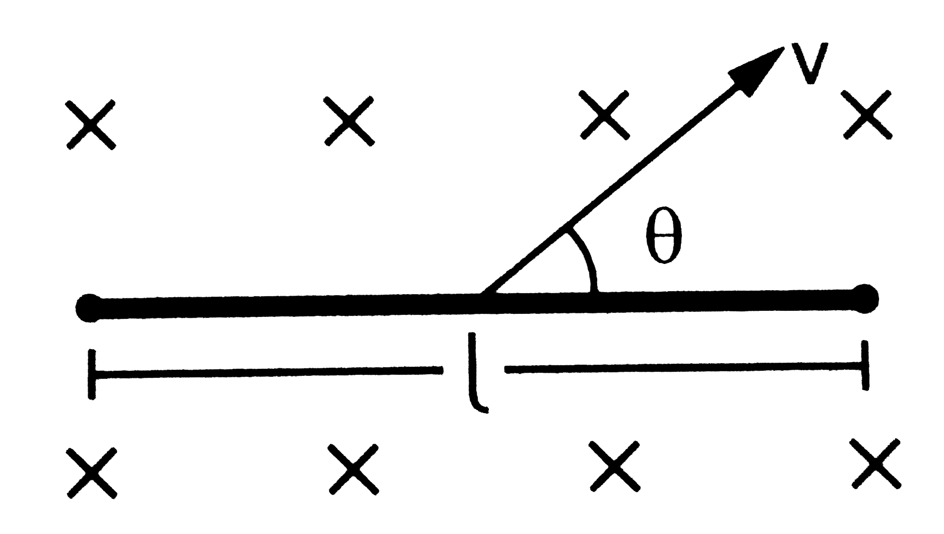
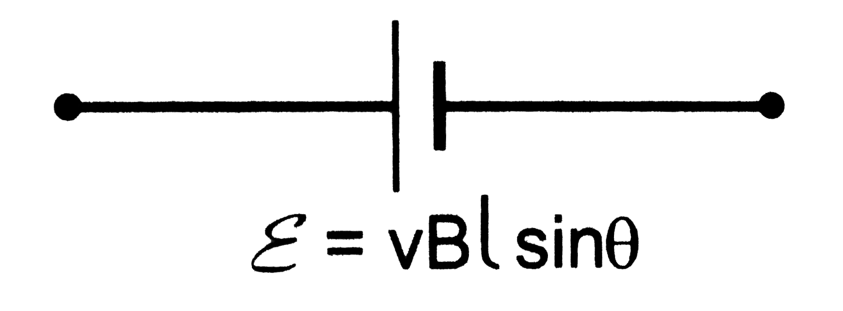
The situation is shown in figure
The component of the velocity perpendicular to the length of the rod is v⊥=sinθ
Only this component is effective in producing the emf in the rod
As the magnetic field is perpendicular to the plane of motion, the emf induced across the ends is ε=v⊥Bl=vBlsinθ
In the figure shown, the positive charges of the rod shift towards left due to the force vec qu X vecB
Thus, the left side of the rod is electrically positive
Figure shows the equivalent battery
EXAMPLE 18
A rod of length l is translating at a velocity v making an angle θ with its length. A uniform magnetic field B exists in a direction perpendicular to the plane of motion. Calculate the emf induced In the rod, Draw a figure representing the induced emf by on equivalent battery.


The situation is shown in figure
The component of the velocity perpendicular to the length of the rod is v⊥=sinθ
Only this component is effective in producing the emf in the rod
As the magnetic field is perpendicular to the plane of motion, the emf induced across the ends is ε=v⊥Bl=vBlsinθ
In the figure shown, the positive charges of the rod shift towards left due to the force vec qu X vecB
Thus, the left side of the rod is electrically positive
Figure shows the equivalent battery
POINT 5
SUMMARY
1. Electricity and magnetism are intimately related. In the early part of the nineteenth century, the experiments of Oersted, Ampere and others established that moving charges (currents) produce a magnetic field. Somewhat later, around 1830, the experiments of Faraday and Henry demonstrated that a moving magnet can induce electric current.
2. In a closed circuit, electric currents are induced so as to oppose the changing magnetic flux. It is as per the law of conservation of energy. However, in case of an open circuit, an emf is induced across its ends. How is it related to the flux change?
3. The magnetic flux through a surface of area A placed in a uniform magnetic field B is defined as, ΦB=B.A=BAcosθ where θ is the angle between B and A.
4. Faraday’s laws of induction imply that the emf induced in a coil of N turns is directly related to the rate of change of flux through it,
ε=−NdΦBdt
Here ΦB is the flux linked with one turn of the coil. If the circuit is closed, a current I=ε/R is set up in it, where R is the resistance of the circuit.
5. Lenz’s law states that the polarity of the induced emf is such that it tends to produce a current which opposes the change in magnetic flux that produces it. The negative sign in the expression for Faraday’s law indicates this fact.
6. The motional emf can be argued independently from Faraday’s law using the Lorentz force on moving charges. However, even if the charges are stationary [and the q(→v×→B) term of the Lorentz force is not operative], an emf is nevertheless induced in the presence of a time-varying magnetic field. Thus, moving charges in a static field and static charges in a time-varying field seem to be symmetric situations for Faraday’s law. This gives a tantalising hint on the relevance of the principle of relativity for Faraday’s law.
7. When a metal rod of length l is placed normal to a uniform magnetic field B and moved with a velocity v perpendicular to the field, the induced emf (called motional emf) across its ends is
ε=Blv
8. The motion of a copper plate is damped when it is allowed to oscillate between the magnetic pole-pieces. How is the damping force, produced by the eddy currents? Changing magnetic fields can set up current loops in nearby metal (any conductor) bodies. They dissipate electrical energy as heat. Such currents are eddy currents.
9. Inductance is the ratio of the flux-linkage to current. It is equal to NΦ/I.
10. A changing current in a coil (coil 2) can induce an emf in a nearby coil (coil 1). This relation is given by,
ε=−M12dI2(dt)
The quantity M12 is called mutual inductance of coil 1 with respect to coil 2. One can similarly define M21. There exists a general equality, M12=M21
8. When a current in a coil changes, it induces a back emf in the same coil. The self-induced emf is given by,
ε=−LdI(dt)
is the self-inductance of the coil. It is a measure of the inertia of the coil against the change of current through it.
11. The self-inductance of a long solenoid, the core of which consists of a magnetic material of relative permeability µ_r , is given by
L=µrµ0n2Al
where A is the area of cross-section of the solenoid, l its length and n the number of turns per unit length.
12. In an ac generator, mechanical energy is converted to electrical energy by virtue of electromagnetic induction. If coil of N turn and area A is rotated at ν revolutions per second in a uniform magnetic field B, then the motional emf produced is ε=NBA(2πν)sin(2πνt) where we have assumed that at time t = 0 s, the coil is perpendicular to the field.
Key Terms
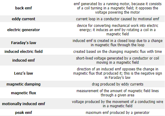
Important Formula
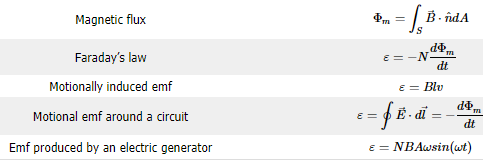
SUMMARY
1. Electricity and magnetism are intimately related. In the early part of the nineteenth century, the experiments of Oersted, Ampere and others established that moving charges (currents) produce a magnetic field. Somewhat later, around 1830, the experiments of Faraday and Henry demonstrated that a moving magnet can induce electric current.
2. In a closed circuit, electric currents are induced so as to oppose the changing magnetic flux. It is as per the law of conservation of energy. However, in case of an open circuit, an emf is induced across its ends. How is it related to the flux change?
3. The magnetic flux through a surface of area A placed in a uniform magnetic field B is defined as, ΦB=B.A=BAcosθ where θ is the angle between B and A.
4. Faraday’s laws of induction imply that the emf induced in a coil of N turns is directly related to the rate of change of flux through it,
ε=−NdΦBdt
Here ΦB is the flux linked with one turn of the coil. If the circuit is closed, a current I=ε/R is set up in it, where R is the resistance of the circuit.
5. Lenz’s law states that the polarity of the induced emf is such that it tends to produce a current which opposes the change in magnetic flux that produces it. The negative sign in the expression for Faraday’s law indicates this fact.
6. The motional emf can be argued independently from Faraday’s law using the Lorentz force on moving charges. However, even if the charges are stationary [and the q(→v×→B) term of the Lorentz force is not operative], an emf is nevertheless induced in the presence of a time-varying magnetic field. Thus, moving charges in a static field and static charges in a time-varying field seem to be symmetric situations for Faraday’s law. This gives a tantalising hint on the relevance of the principle of relativity for Faraday’s law.
7. When a metal rod of length l is placed normal to a uniform magnetic field B and moved with a velocity v perpendicular to the field, the induced emf (called motional emf) across its ends is
ε=Blv
8. The motion of a copper plate is damped when it is allowed to oscillate between the magnetic pole-pieces. How is the damping force, produced by the eddy currents? Changing magnetic fields can set up current loops in nearby metal (any conductor) bodies. They dissipate electrical energy as heat. Such currents are eddy currents.
9. Inductance is the ratio of the flux-linkage to current. It is equal to NΦ/I.
10. A changing current in a coil (coil 2) can induce an emf in a nearby coil (coil 1). This relation is given by,
ε=−M12dI2(dt)
The quantity M12 is called mutual inductance of coil 1 with respect to coil 2. One can similarly define M21. There exists a general equality, M12=M21
8. When a current in a coil changes, it induces a back emf in the same coil. The self-induced emf is given by,
ε=−LdI(dt)
is the self-inductance of the coil. It is a measure of the inertia of the coil against the change of current through it.
11. The self-inductance of a long solenoid, the core of which consists of a magnetic material of relative permeability µr , is given by
L=µrµ0n2Al
where A is the area of cross-section of the solenoid, l its length and n the number of turns per unit length.
12. In an ac generator, mechanical energy is converted to electrical energy by virtue of electromagnetic induction. If coil of N turn and area A is rotated at ν revolutions per second in a uniform magnetic field B, then the motional emf produced is ε=NBA(2πν)sin(2πνt) where we have assumed that at time t = 0 s, the coil is perpendicular to the field.
Key Terms

Important Formula

EXAMPLE 23
Find the current in the sliding rod AB (resistance = R) for the arrangement shown in figure. B is constant and is out of the paper. Parallel wires have no resistance , v is constant . Switch S is closed at time t=0.
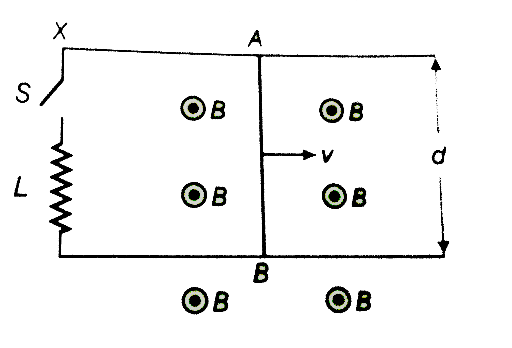
The conductor of length d moves with speed v1 perpendicular to magnetic field B as shown in figure. The produces motional emf across two ends of rod. Which is given by =vBd. Since, switch S is closed at time t=0 current starts growing in the inductor by the potential difference due to motional emf.
Applying Kichhoff's voltage rule, we have
−LdIdt+vBd=IRorLdIdt+IR=vBd
This is the linear difference equation. On solving, we get
l=vBdR+AeRT/2
At t=0l=0
⇒A=−vBdR⇒IvBdR(1−e−RT/L)
This is the required expression of current.
EXAMPLE 25
A (current versus time ) graph of the current passing through a solenoid is shown in figure. For which time is the back electromotive force (u) a maximum. If the back emf at t= 3 s is e, find the back emf at t=7,15s and 40s. AB and BC are straight line segments.
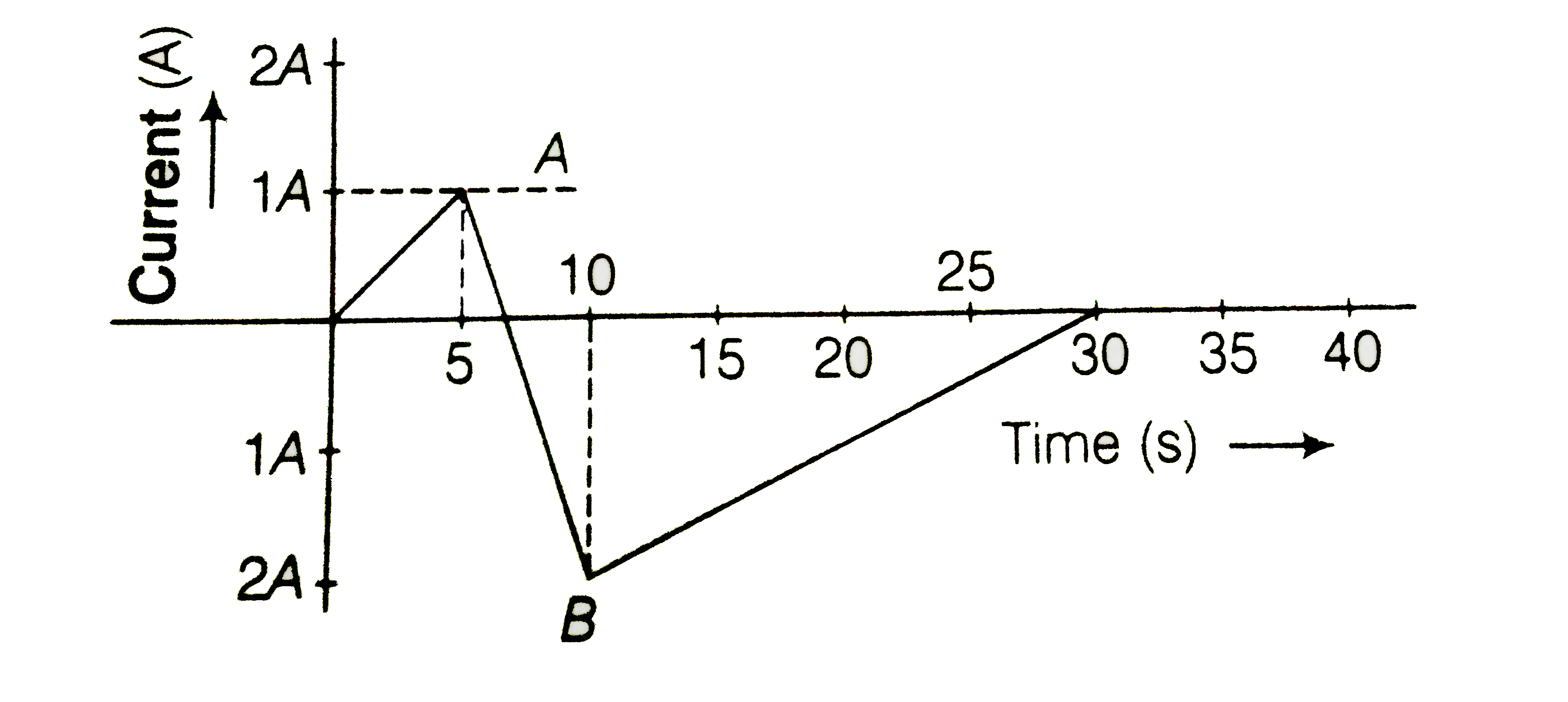
The back electromotive force in solenoid is (u) a maximum when there is maximum rate of change of current. This occurs in AB part of the graph. So maximum back emf will be obtained between 5s<t<10s.
Since the back emf at t= 3s is e,
Also,
the rate of change of current at t=3,s= slope of OA from t=0s to t=5s=1/5A/s.
So, we have
If u=L1/5(fort=3s,dIdt=1/5) (L is a constant). Applying ε=−LdIdt
Similarly, we have for other values
For 5s<t<10s
u1=−L35=−35L=−3e
Thus, at t=7s,u1=−3e
For 10s<t<30s
u−2=L220=L10=12e
For t>30s,u2=0
Thus, the back emf at t=7s,15s and 30s are −3e,e/2 and 0 respectively .
EXAMPLE 26
Three are two coils A and B separated by some distance. If a current of 2A flows through A, a magnetic flux of 10−2 Wb through B (no current through B ). If no current passes through A and a current of 1A passes through B, what is the flux through A ?
Applying the mutual inductance of coil A with respect to coil B M21=N2ϕ2I1
Therefore, we have
mutual inductance =10−22=5mH
Again applying this formula for other case
N1ϕ1=M12I2=5mH×1A=5mWb.
EXAMPLE 27
A rectangular loop of wire ABCD is kept close to an infinitely long wire carrying a current l(t)=I0(1−t/T) for 0≤t≤T and l(0)=0 for t>T (figure). Find the total charge passing through a given point in the loop , in time T. The resistance of the loop is R.
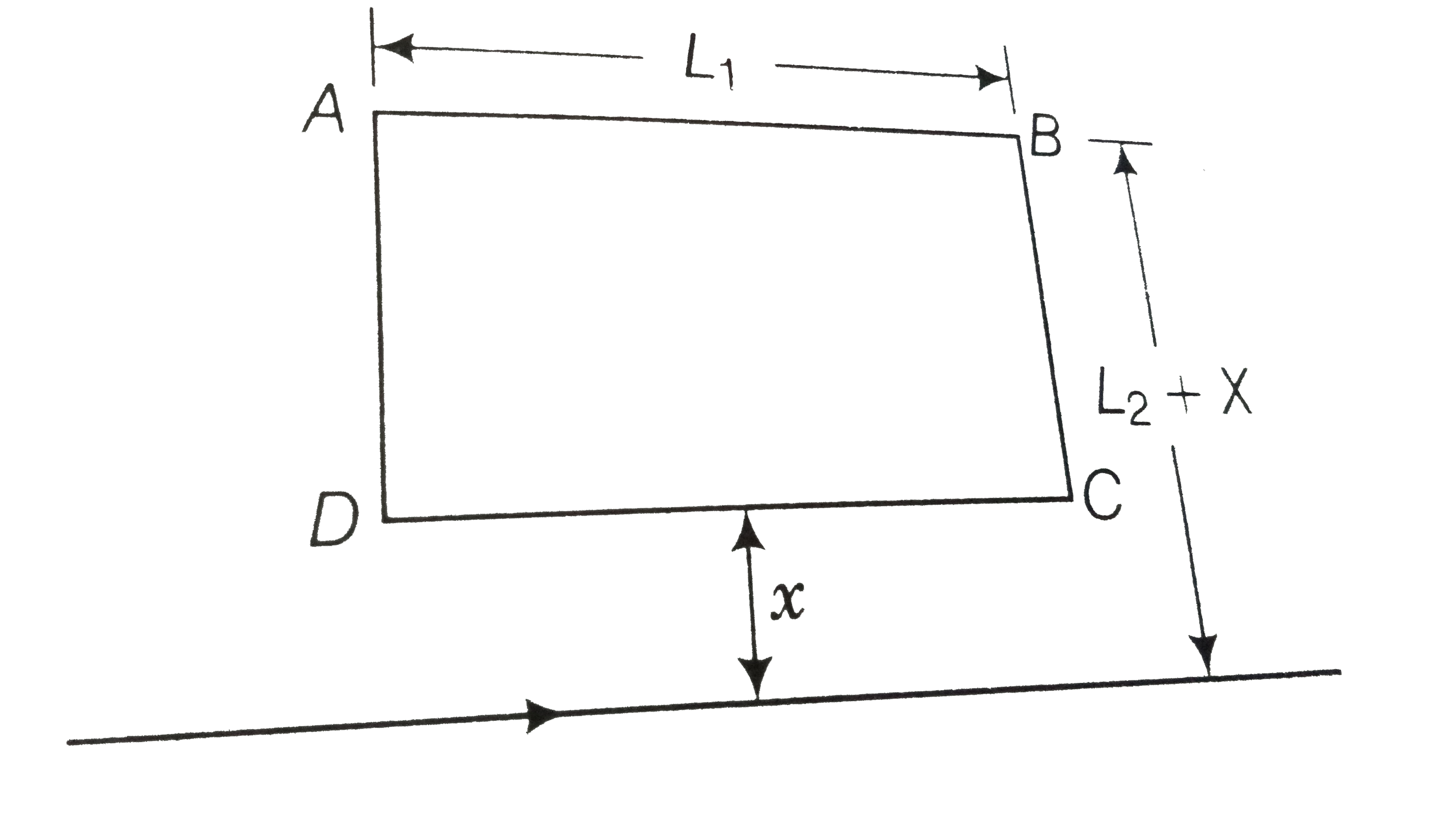
The emf induced can be obtained by differentiating the expression on magnetic flux linked wrt t and then applying Ohm's law
I=ER=1Rdϕdt
We know that electric current I(t)=dQdtorDqdt=1dϕRdt
Integrating the variable separable form of differential equation for finding the charge Q that passed in time t, we have
Q(t1)−Q(t2)=1R[ϕ(t1)−ϕ(t2)]
ϕ(t1)=L1μ02π∫L2+xxdx1x1I(t1) [Refer to the Eq. (i) of answer no. 25]
=μ0L12πI(t1)InL2+xx
The magnitude of charge is given by , =μ0L12πInL2+xx[I0=0]
=μ0L12πI1In(L2+xx)
This is the required expression .
EXAMPLE 28
Two concentric circular coils, one of small radius r_1 and the other of large radius r_2, such that r1 << r2, are placed co-axially with centres coinciding. Obtain the mutual inductance of the arrangement.
Let a current I_2 flow through the outer circular coil. The field at the centre of the coil is B2=μ0I22r2. Since the other co-axially placed coil has a very small radius, B_2 may be considered constant over its cross-sectional area. Hence,
Φ1=πr2_1B2
=(μ0πr2_12r2)I2
=M12I2
Thus, M12=μ0πr2_1
M12=M21 =(μ0πr2_12r2)I2
Note that we calculated M12 from an approximate value of Φ1, assuming the magnetic field B2 to be uniform over the area πr2_1 . However, we can accept this value because r1⟨r2.
A.C. GENERATOR
A.C. generator ka mtlb "Alternating Current generator" hai. A.C. generator ka use hum factory ya ghar pr karte hain jab mains se electric supply nahi hoti hai, as an alternative source of electricity. A.C. generator alternating current produce karta hai jo apna direction continuously reverse karta hai. A.C. generator ko alternator bhi kahte hain. The current which changes direction after equal intervals of time, is called an alternating current (abbreviated as AC). This device is called an AC generator.
PRINCIPLE
A.C. generator mechanical energy ko electrical energy me convert karta hai.Generator me coil magnetic field me rotate karta hai. Is rotation ke karan magnetic flux jo coil se link hota hai vo change karta hai aur isliye e.m.f. (electromotive force) coil ke ends ke beech me induce hota hai. Generator load containing external circuit me source of current ke tarah act karta jab usse coil ke dono ends ke beech join karte hain.

CONSTRUCTION AND MAIN PARTS of A.C. GENERATOR
The main parts of an a.c. generator are:1. A horseshoe electromagnet NS,
2. The armature coil ABCD,
3. The slip rings S1, S2, and
4. The brushes B1, B2.
Horseshoe electromagnet NS: Ye strong magnet hai N aur S poles ka.
Armature coil ABCD: Soft iron core ka ka arms ABCD hai jisko armature coil kehte hai. Ispr insulated wire wound hain with many turns. Ye coil rapidly magnetic field me rotate hota hai poles of field magnet ke beech, by an axle fixed to it.
Slip rings S1 and S2: Slip ring cylindrical circular pipe hota hai. Do coaxial metallic rings S1 aur S2 hote hain jo coil ke along rotate hota hai. Jab coil rotate krta hai, to slip rings bhi rotate krte hain. Coil ka ek end slip ring S1 se connected hota hai aur dusra end slip ring S2 se connected hota hai.
Dono ring stationary brush ke against slip karta hai.
Brushes B1 and B2: Do carbon brushes B1 aur B2 slip rings S1 aur S2 ke against gently press hote hain. Brushes electrical connection ke jaisa act krte hai slip rings aur electrical component ya load ke beech. Brushes ke dusre end generator ke terminal ke tarah act karte hain jiske across load containing external circuit connected hote hain. Brushes B1 aur B2 coil aur slip rings ke along slip nahi karte hain.

WORKING OF A.C. GENERATOR
Jab armature poles of field magnet ke beech rotate karta hai to armature se linked magnetic flux continuously change karta hai. Is karan armature me e.m.f. (electromotive force) induce hota hai jiske karan electric current produce hota hai.Jab armature clockwise direction me rotate karta hai, tab Flemming’s right hand rule ko apply karke, external circuit me induced current ko find kr sakte hain. Induced current opposite direction me flow hota hai jiske karan galvanometer me deflection ka direction left me hota hai.
Thus, we see that the direction of induced current changes in the external circuit after every half revolution of the armature, i.e., after the armature has turned through an angle of 180° from its initial position. Hence, the induced current is alternating in nature.
WORKING FORMULA
Jab coil constant angular speed ω se rotate krta hai to magnetic field vector B aur coil ka area vector A ke beech ka angle θ at any instant t is θ=ωt (assuming θ = 0º at t = 0).Iske karan jo coil ka area magnetic field me hain vo time ke saath km ho jata hai. Flux at any time t is (ΦB)=BAcosθ
=BAcosωt
Faraday’s law se, ε=−NdΦBdt
=−NBAddt(cosωt)
So, emf ka instantaneous value, ε=NBAωsinωt
Yaha pr NBAω emf ka maximum value hai, ye tab hota hai jab sinωt=±1. Ager hum NBAω ko ε0 denote kre, to ε=ε0sinωt.
Sine function ka value +1 aur –1 ke beech hota hai isliye emf ka sign ya polarity time ke saath change hota hai.
Since ω=2πν, so ε=ε0sin2πνt
Yaha pr v generator ke coil ke revolution ka frequency hai.
1. Emf has its extremum value when θ=90º or θ=270º, as the change of flux is greatest at these points.
2. The direction of the current changes periodically and therefore the current is called alternating current (ac).
POINT 6
The peak emf of a generator is ε0=NBAω.
Any rotating coil produces an induced emf. In motors, this is called back emf because it opposes the emf input to the motor.
EXAMPLE 29
A magnetic field B is confined to a region r≤a and points out of the paper (the z-axis),r=0 being the centre of the circular region. A charged ring (charge=Q) of radius b,b>a and mass m lies in the x−y plane with its centre at the origin. The ring is free to rotate and is at rest. The magnetic field is brought to zero in time. Δt. Find the angular velocity ω of the ring after the field vanishes.
Since, the magnetic field is brought to zero in time Δt, the magnetic flux linked with the ring also reduces from maximum to zero. Thus, in turn, induces an emf in ring by the phenomenon of EMI. The induces emf causes the electric field E generation around the ring.
The induced emf = electric field E x (2πb) (Because V=E×d)............(i)
By Faraday's law of EMI
The induced emf = rate of change of magnetic flux = rate of change of magnetic field x area
=Bπa2Δt.............(ii)
From eqs. (i) and (ii), we have
2πbE=emf=Bπa2Δt
Since, the charged ring experienced a electric force = QE
This force try to rotate the coil, and the torque is given by
Torque = b x Force
=QEb=Q[Bπa22πbΔt]b
=QBa22Δt
If ΔL is the change in angular momentum
ΔL=Torque×Δt=QBa22
Since, initial angular momentum =0
Now,since Torque x Δt= Change in angular momentum
Final angular momentum =mb2ω=QBa22
ω=QBa22mb2
On rearranging the terms, we have the required expression of angular speed.
EXAMPLE 30
Kamla peddles a stationary bicycle the pedals of the bicycle are attached to a 100 turn coil of area 0.10 m2 . The coil rotates at half a revolution per second and it is placed in a uniform magnetic field of 0.01 T perpendicular to the axis of rotation of the coil. What is the maximum voltage generated in the coil?
Here f = 0.5 Hz; N =100, A = 0.1 m2 and B = 0.01 T.
ε0 = NBA (2 π ν) = 100 × 0.01 × 0.1 × 2 × 3.14 × 0.5 = 0.314 V
The maximum voltage is 0.314 V. We urge you to explore such alternative possibilities for power generation.
SUMMARY
1. Electricity and magnetism are intimately related. In the early part of the nineteenth century, the experiments of Oersted, Ampere and others established that moving charges (currents) produce a magnetic field. Somewhat later, around 1830, the experiments of Faraday and Henry demonstrated that a moving magnet can induce electric current.
2. In a closed circuit, electric currents are induced so as to oppose the changing magnetic flux. It is as per the law of conservation of energy. However, in case of an open circuit, an emf is induced across its ends. How is it related to the flux change?
3. The magnetic flux through a surface of area A placed in a uniform magnetic field B is defined as, ΦB=B.A=BAcosθ where θ is the angle between B and A.
4. Faraday’s laws of induction imply that the emf induced in a coil of N turns is directly related to the rate of change of flux through it,
ε=−NdΦBdt
Here ΦB is the flux linked with one turn of the coil. If the circuit is closed, a current I=ε/R is set up in it, where R is the resistance of the circuit.
5. Lenz’s law states that the polarity of the induced emf is such that it tends to produce a current which opposes the change in magnetic flux that produces it. The negative sign in the expression for Faraday’s law indicates this fact.
6. The motional emf can be argued independently from Faraday’s law using the Lorentz force on moving charges. However, even if the charges are stationary [and the q(→v×→B) term of the Lorentz force is not operative], an emf is nevertheless induced in the presence of a time-varying magnetic field. Thus, moving charges in a static field and static charges in a time-varying field seem to be symmetric situations for Faraday’s law. This gives a tantalising hint on the relevance of the principle of relativity for Faraday’s law.
7. When a metal rod of length l is placed normal to a uniform magnetic field B and moved with a velocity v perpendicular to the field, the induced emf (called motional emf) across its ends is
ε=Blv
8. The motion of a copper plate is damped when it is allowed to oscillate between the magnetic pole-pieces. How is the damping force, produced by the eddy currents? Changing magnetic fields can set up current loops in nearby metal (any conductor) bodies. They dissipate electrical energy as heat. Such currents are eddy currents.
9. Inductance is the ratio of the flux-linkage to current. It is equal to NΦ/I.
10. A changing current in a coil (coil 2) can induce an emf in a nearby coil (coil 1). This relation is given by,
ε=−M12dI2(dt)
The quantity M12 is called mutual inductance of coil 1 with respect to coil 2. One can similarly define M21. There exists a general equality, M12=M21
8. When a current in a coil changes, it induces a back emf in the same coil. The self-induced emf is given by,
ε=−LdI(dt)
is the self-inductance of the coil. It is a measure of the inertia of the coil against the change of current through it.
11. The self-inductance of a long solenoid, the core of which consists of a magnetic material of relative permeability µr , is given by
L=µrµ0n2Al
where A is the area of cross-section of the solenoid, l its length and n the number of turns per unit length.
12. In an ac generator, mechanical energy is converted to electrical energy by virtue of electromagnetic induction. If coil of N turn and area A is rotated at ν revolutions per second in a uniform magnetic field B, then the motional emf produced is ε=NBA(2πν)sin(2πνt) where we have assumed that at time t = 0 s, the coil is perpendicular to the field.
Key Terms

Important Formula
