CAPACITOR for Class 12 PHYSICS
INTRODUCTION
Baccho jaise aapne market me rechargeable battery dekhi hi hogi, toh voh battery baccho charge ko store krke rakhti hai.
Baccho esi cheez jo energy store krke rakhe in the form of charge jab do plates ke beech potentia difference ho, use hum capacitor bolte hai.
There are many different kinds of capacitors available from very small capacitor beads used in resonance circuits to large power factor correction capacitors, but they all do the same thing, they store charge.
CAPACITORS AND CAPACITANCE
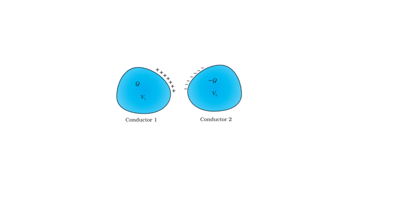
Capacitor do conductor wala system hota hai jo ki insulator se separated hota hai.
Jaisa ki aap diagram me dekh sakte hai dono conductors prr charges Q and −Q hai and potentials V1 and V2 hai. Inn conductors ko hum charge kar sakte hai by connecting both the conductors by two terminal of the battery.
Bachho “the electric field in the region between the conductors is proportional to the charge Q”, iska mtlb hai baccho ki agr capacitor ki capacity double krdi jaaye toh electric field bhi double ho jaegi har point prr.
Therefore ,
C=QV, where C is the capacitance of the capacitor and C is independent of Q and V.
The capacitor C only depends upon size, shape and configuration of the capacitance.
And the SI unit of capacitance is 1 Farad.
CAPACITORS AND CAPACITANCE

Capacitor do conductor wala system hota hai jo ki insulator se separated hota hai.
Jaisa ki aap diagram me dekh sakte hai dono conductors prr charges Q and −Q hai and potentials V1 and V2 hai. Inn conductors ko hum charge kar sakte hai by connecting both the conductors by two terminal of the battery.
Bachho “the electric field in the region between the conductors is proportional to the charge Q”, iska mtlb hai baccho ki agr capacitor ki capacity double krdi jaaye toh electric field bhi double ho jaegi har point prr.
Therefore ,
C=QV, where C is the capacitance of the capacitor and C is independent of Q and V.
The capacitor C only depends upon size, shape and configuration of the capacitance.
And the SI unit of capacitance is 1 Farad.
PARALLEL PLATE CAPACITOR
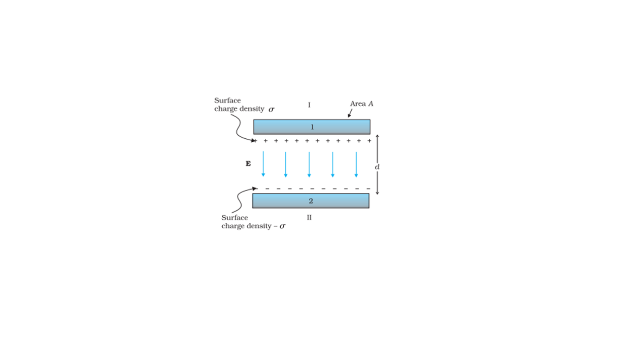
A parallel plate capacitor consists of two large plane parallel conducting plates separated by a small distance.
First we take the medium between the plates as vacuum, means no medium.
Now let A be the area of each plate and d be the separation between the plates.
Dono plates prr charge Q and −Q hai.
Ab jaisa ki aap dekh sakte hai ki d separation bhut chota hai as compare to area of each plate A, toh hum inn plates ko infinite plate maan sakte hai, ab infinite surface charge density ki wajah se electric filed hogi.
Ab plate 1 ki surface charge density hogi σ=QA and plate 2 ki hogi
σ=−QA.
Ab baccho jo outer region hai usme electric field ) hogi or inner region me electric field hogi.and jo inner region me electric field hogi voh hogi
E=σ2ε0+σ2ε0=σε0
Therefore E=Qε0A and jo direction hogi electric field ki voh positive plate to negative plate hogi.
Now we know that, potential difference, V=Ed
So, V=Qdε0A,
Therefore the capacitance C of the parallel plate capacitor is,
C=QV
C=ε0Ad
PARALLEL PLATE CAPACITOR

A parallel plate capacitor consists of two large plane parallel conducting plates separated by a small distance.
First we take the medium between the plates as vacuum, means no medium.
Now let A be the area of each plate and d be the separation between the plates.
Dono plates prr charge Q and −Q hai.
Ab jaisa ki aap dekh sakte hai ki d separation bhut chota hai as compare to area of each plate A, toh hum inn plates ko infinite plate maan sakte hai, ab infinite surface charge density ki wajah se electric filed hogi.
Ab plate 1 ki surface charge density hogi σ=QA and plate 2 ki hogi
σ=−QA.
Ab baccho jo outer region hai usme electric field ) hogi or inner region me electric field hogi.and jo inner region me electric field hogi voh hogi
E=σ2ε0+σ2ε0=σε0
Therefore E=Qε0A and jo direction hogi electric field ki voh positive plate to negative plate hogi.
Now we know that, potential difference, V=Ed
So, V=Qdε0A,
Therefore the capacitance C of the parallel plate capacitor is,
C=QV
C=ε0Ad
EFFECT OF DIELECTRIC ON CAPACITANCE
Baccho jab kisi parallel plate capacitor ya normal capacitor ke beech me hum agr koi medium inset krde, use hum dielectric bolte hai and ise hum K se denote krte hai,
agr normal parallel plate capacitor ki capacitance ki baat krein toh voh hota hai,
C=ε0Ad
And jab dielectric insert ki jaati hai plates ke beech me jiska dielectric constant K hai toh uska capacitance K times increase ho jata hai.
Therefore , capacitance C will become, C=Kε0Ad, where Kε0 is called the permittivity of the medium and is denoted by ε=Kε0 where ε0 is the permittivity of the vacuum.
SERIES COMBINATION OF CAPACITORS
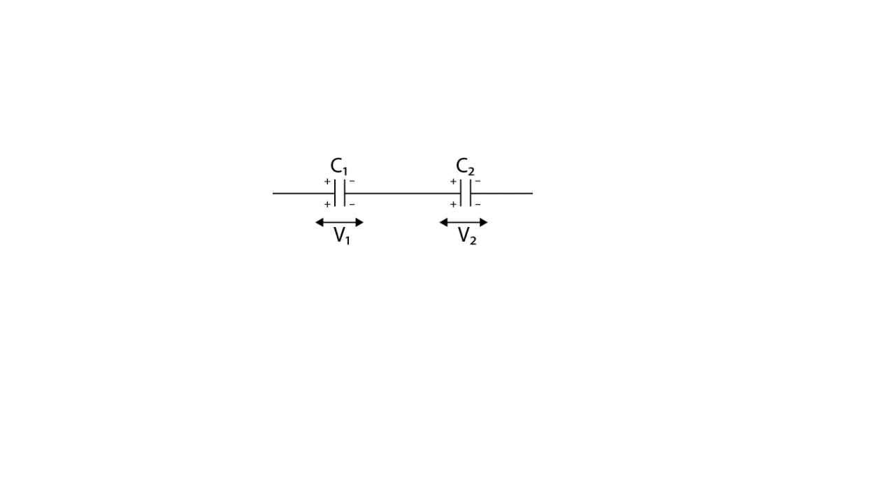
The left plate of C1 and the right plate of C2 are connected to two terminals of a battery and have charges Q and –Q , respectively.It then follows that the right plate of C1 has charge –Q and the left plate of C2 has charge Q.
Ab charge jab tk flow krega jab tk dono capactiors prr net charge zero nhi ho jata and there is no electric field in the conductor connecting C1 and C2.
Therefore in series combination,
Total potential difference is equal to the sum of the potential drop V1 and V2 across the capacitor C1 and C2.
Hence,
V=V1+V2
V=QC1+QC2
Now we can write,
VQ=1C1+1C2
Now the effective capacitance of the combination is-
C=QV
After combining these two equation, we get,
1C=1C1+1C2
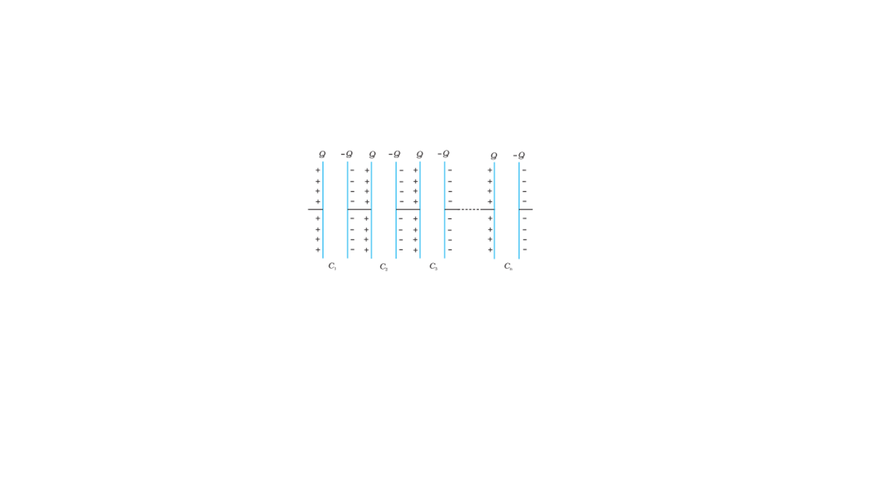
If we connect n capacitors in series then the effective capacitance of the combination would be,
1C=1C1+1C2+1C3+..........+(1Cn)
SERIES COMBINATION OF CAPACITORS

The left plate of C1 and the right plate of C2 are connected to two terminals of a battery and have charges Q and –Q , respectively.It then follows that the right plate of C1 has charge –Q and the left plate of C2 has charge Q.
Ab charge jab tk flow krega jab tk dono capactiors prr net charge zero nhi ho jata and there is no electric field in the conductor connecting C1 and C2.
Therefore in series combination,
Total potential difference is equal to the sum of the potential drop V1 and V2 across the capacitor C1 and C2.
Hence,
V=V1+V2
V=QC1+QC2
Now we can write,
VQ=1C1+1C2
Now the effective capacitance of the combination is-
C=QV
After combining these two equation, we get,
1C=1C1+1C2

If we connect n capacitors in series then the effective capacitance of the combination would be,
1C=1C1+1C2+1C3+..........+(1Cn)
PARALLEL COMBINATION OF CAPACITORS
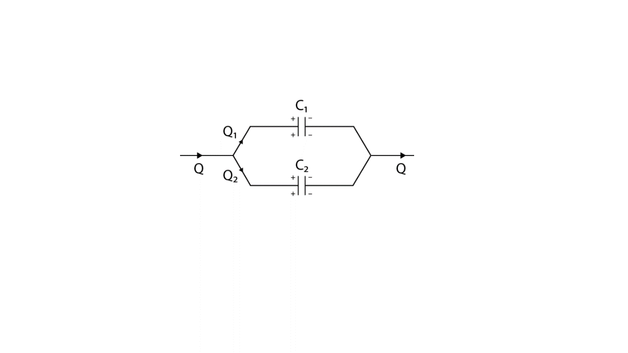
Iss combination me dono capacitors C1 and C2 ke across potential difference same drop hoga prr charges same aaye esa koi jaruri nhi hai,
Maan lete hai capacitor C1 prr charge Q1 drop hua hai and C2 capacitor prr charge Q2 drop hua hai.
Therefore , Q1=C1V and Q2=C2V
The equivalent capacitor is one with charge
Q=Q1+Q2
CV=C1V+C2V
Therefore , effective capacitance is C=C1+C2
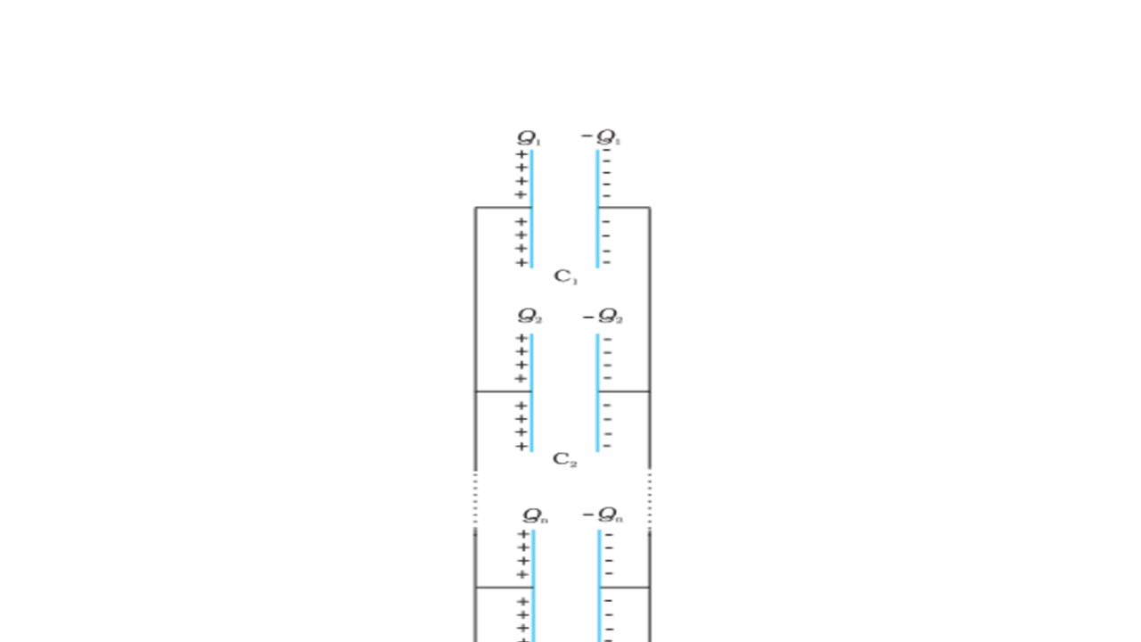
Now the equivalent capacitance of n capacitors connected in parallel would be written as, C=C1+C2+C3+..........+Cn
PARALLEL COMBINATION OF CAPACITORS

Iss combination me dono capacitors C1 and C2 ke across potential difference same drop hoga prr charges same aaye esa koi jaruri nhi hai,
Maan lete hai capacitor C1 prr charge Q1 drop hua hai and C2 capacitor prr charge Q2 drop hua hai.
Therefore , Q1=C1V and Q2=C2V
The equivalent capacitor is one with charge
Q=Q1+Q2
CV=C1V+C2V
Therefore , effective capacitance is C=C1+C2

Now the equivalent capacitance of n capacitors connected in parallel would be written as, C=C1+C2+C3+..........+Cn
ENERGY STORED IN A CAPACITOR
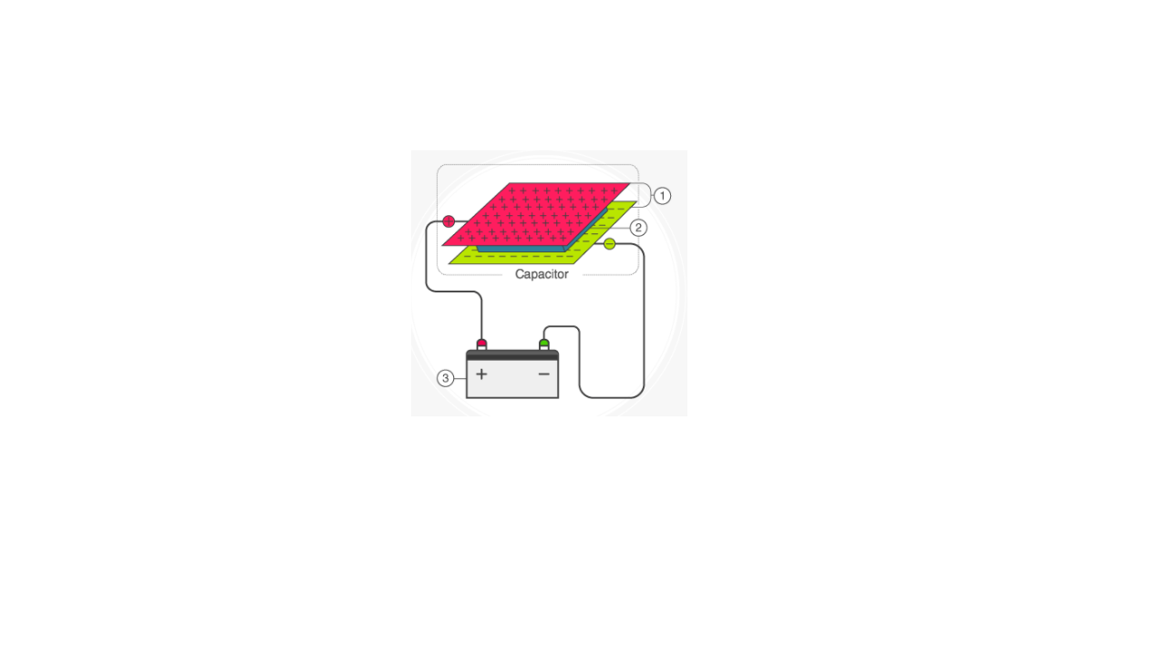
Energy stored in a capacitor kuch bhi nh hai bss ek tarah ki electric potential energy hai and ye voltage and charge se related hai.If the capacitance of a conductor is C, starting me ye uncharge hai and iske across potential difference V generate ho jata hai jab ise ek battery se connect krte hai.
If q charge is on tha plate at time t,
Then q=CV,
The work done is equal to the product of the potential and charge. Hence, W=Vq
Agr battery small amount of charge dq deta hai jab uskaconstant potential difference V hai, then the workdone is-
dW=Vdq=qCdq
Now, the total work done in delivering a charge of an amount q to the capacitor is given by,
W=intq/Cdq, where limits is from 0 to 1.
Therefore,
W=q22C,
Now substituting q=CV, we get,
W=12CV2
Now this workdone is stored in the form of potential energy of the capacitor,
Therefore, the energy stored int a capacitor is given by,
U=12CV2
ENERGY STORED IN A CAPACITOR

Energy stored in a capacitor kuch bhi nh hai bss ek tarah ki electric potential energy hai and ye voltage and charge se related hai.If the capacitance of a conductor is C, starting me ye uncharge hai and iske across potential difference V generate ho jata hai jab ise ek battery se connect krte hai.
If q charge is on tha plate at time t,
Then q=CV,
The work done is equal to the product of the potential and charge. Hence, W=Vq
Agr battery small amount of charge dq deta hai jab uskaconstant potential difference V hai, then the workdone is-
dW=Vdq=qCdq
Now, the total work done in delivering a charge of an amount q to the capacitor is given by,
W=intq/Cdq, where limits is from 0 to 1.
Therefore,
W=q22C,
Now substituting q=CV, we get,
W=12CV2
Now this workdone is stored in the form of potential energy of the capacitor,
Therefore, the energy stored int a capacitor is given by,
U=12CV2
EXAMPLE 1
Two very large thin conducting plates having same cross sectional area are placed as shown in figure. They are carrying charges Q and 3Q, respectively. The variation of electric field as a function at x (for x=0 to x=3d) will be best represented by
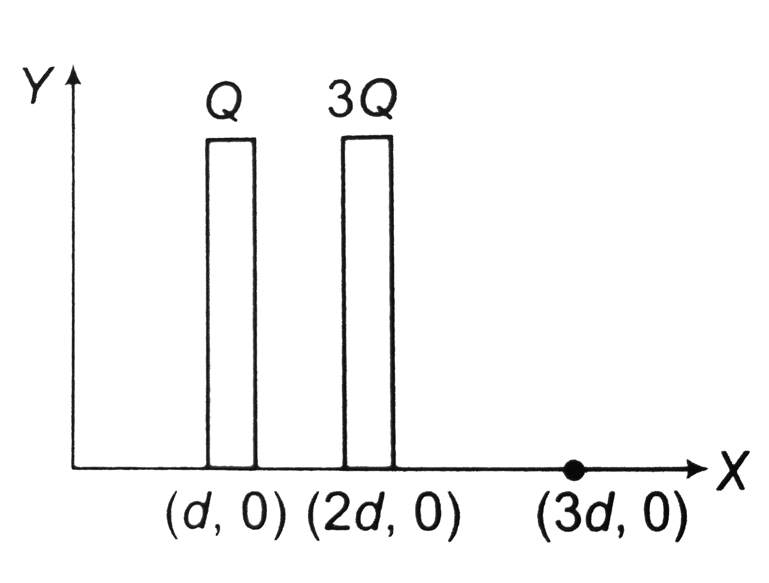
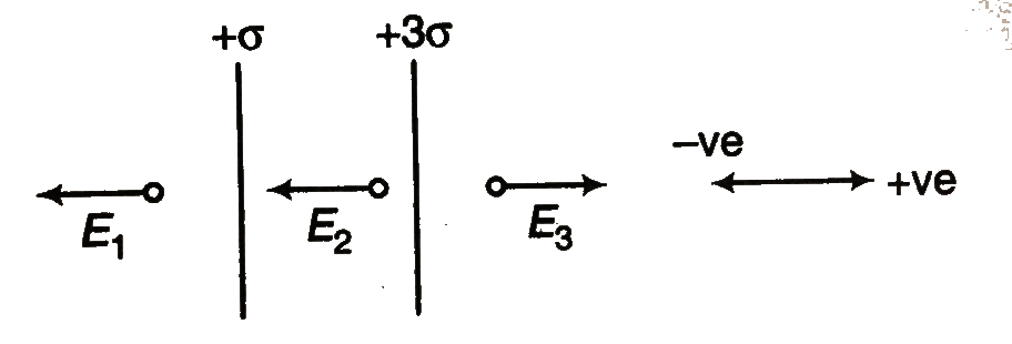
E1=σ2ε0+3σ2ε0=2σε0=E3
E2=3σ2ε0−σ2ε0=σε0
E1andE2 are in the negative direction and E3 in positive direction.
EXAMPLE 1
Two very large thin conducting plates having same cross sectional area are placed as shown in figure. They are carrying charges Q and 3Q, respectively. The variation of electric field as a function at x (for x=0 to x=3d) will be best represented by


E1=σ2ε0+3σ2ε0=2σε0=E3
E2=3σ2ε0−σ2ε0=σε0
E1andE2 are in the negative direction and E3 in positive direction.
EXAMPLE 2
What charges will flow through A,B and C in the direction shown in the figure when swithc S is closed?
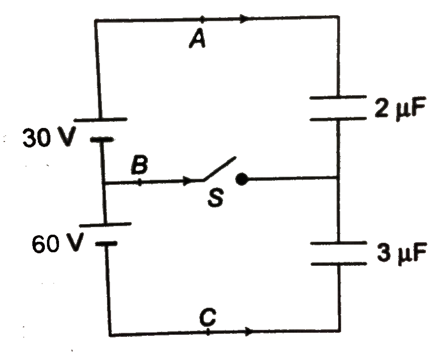
Let us draw two figure and find the charge on both the capacitors before closing the switch and after closing the switch. 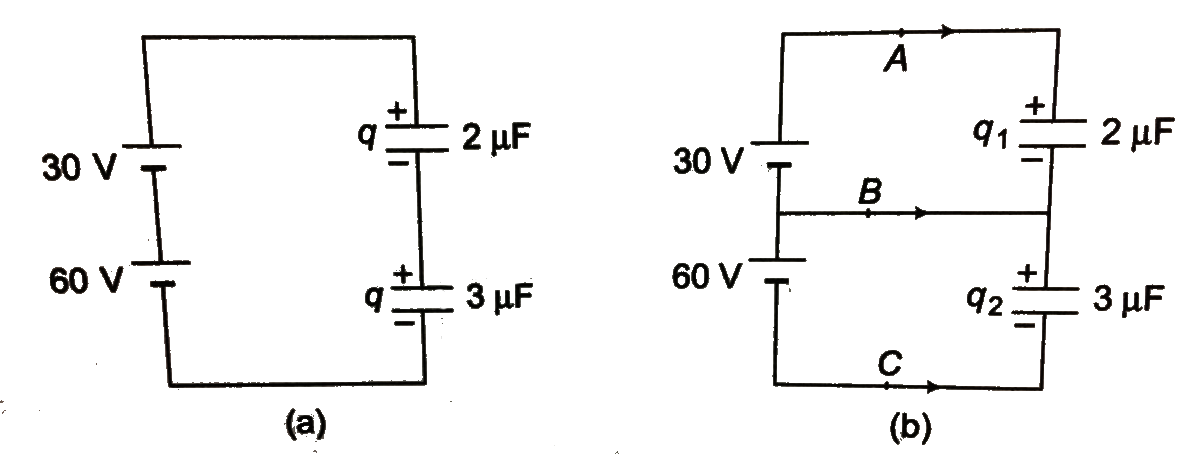
Refer fig a. when switch is open Both capacitors are in series. Hence, their equivalent capacitance is
Ceq=C1C2C1+C2(2)(3)2+3=65μF
therefore, charge on both capacitors will be same, Hence, using q=CV we get
q=(30+60)(65)μC=108μC
Refer fig b. when switch is closed Let q1 and q2 be the charges (inμC) on two capacitors. Then applying second law in upper and lower loops, we have
30−q12=0 or q1=60μC
60−q23=0 or q2=180μC
Charges q1 and q2 can be calculated alternatively by seeing that upper plate of 2μF capcior is connected with positive terminal of 30V battery. THereforwe, they are at the same potential. Similarly, thelower plate of this capacitor is at the same potential as that of the negative terminal of 30V battery. So, we can say that PD across 2μF capacitor is also 30V.
q1=(C)(PD)=(2)(30)μC
=60μC
Similarly PD across 3μF capacitor is same as that between 60V battery. hence,
q2=(3)(60)μC
=180μC
Now let qA charge flows from A in the direction shown. This charge goes to the upper plate of 2μF capacitor. initialy, it had charge +q and final charge on it is +q1 Hence
q1=q+qA
or qA=q1−q=60−108
=−48μC
Similarly charge qB goes to the upper plate of 3μF capacitor and lower plate of 2μF capacitor. INitially both the plates had a chaerge +q−q or zero. And finally they have a charge (q2−q1)
Hence
(q2−q1)=qB+0
∴qB=q2−q1=180−60
=120μC
Charge qC goes to the lower plate of 3μF capacitor. Initially, it had a charge −q and finally −q2 Hence ltbr −q2=(−q)+qC
qC=q−q2=108−180
=−72μC
so, the charges will flow as shown below

EXAMPLE 2
What charges will flow through A,B and C in the direction shown in the figure when swithc S is closed?

Let us draw two figure and find the charge on both the capacitors before closing the switch and after closing the switch. 
Refer fig a. when switch is open Both capacitors are in series. Hence, their equivalent capacitance is
Ceq=C1C2C1+C2(2)(3)2+3=65μF
therefore, charge on both capacitors will be same, Hence, using q=CV we get
q=(30+60)(65)μC=108μC
Refer fig b. when switch is closed Let q1 and q2 be the charges (inμC) on two capacitors. Then applying second law in upper and lower loops, we have
30−q12=0 or q1=60μC
60−q23=0 or q2=180μC
Charges q1 and q2 can be calculated alternatively by seeing that upper plate of 2μF capcior is connected with positive terminal of 30V battery. THereforwe, they are at the same potential. Similarly, thelower plate of this capacitor is at the same potential as that of the negative terminal of 30V battery. So, we can say that PD across 2μF capacitor is also 30V.
q1=(C)(PD)=(2)(30)μC
=60μC
Similarly PD across 3μF capacitor is same as that between 60V battery. hence,
q2=(3)(60)μC
=180μC
Now let qA charge flows from A in the direction shown. This charge goes to the upper plate of 2μF capacitor. initialy, it had charge +q and final charge on it is +q1 Hence
q1=q+qA
or qA=q1−q=60−108
=−48μC
Similarly charge qB goes to the upper plate of 3μF capacitor and lower plate of 2μF capacitor. INitially both the plates had a chaerge +q−q or zero. And finally they have a charge (q2−q1)
Hence
(q2−q1)=qB+0
∴qB=q2−q1=180−60
=120μC
Charge qC goes to the lower plate of 3μF capacitor. Initially, it had a charge −q and finally −q2 Hence ltbr −q2=(−q)+qC
qC=q−q2=108−180
=−72μC
EXAMPLE 3
The potential difference between points a and b of circuits shown in figure is
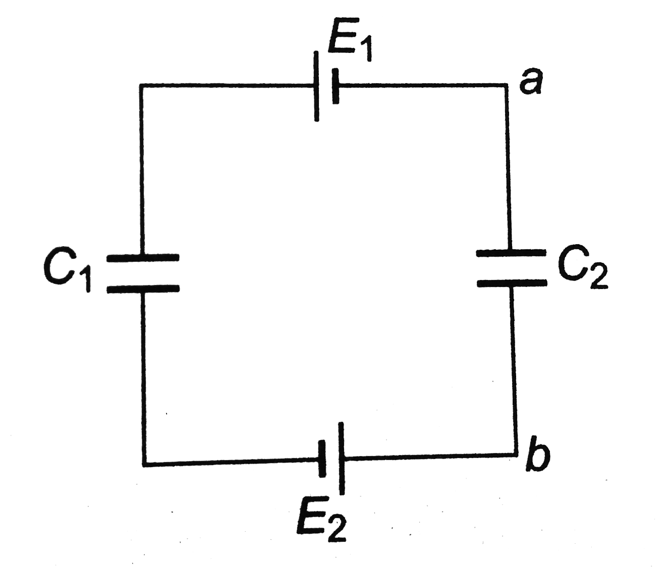
q=(E1+E2)Cnet
=(E1+E2)C1C2C2+C2
Vab=qC2=(E1+E2C1+C2)C1
EXAMPLE 3
The potential difference between points a and b of circuits shown in figure is

q=(E1+E2)Cnet
=(E1+E2)C1C2C2+C2
Vab=qC2=(E1+E2C1+C2)C1
EXAMPLE 4
In the circuit shown in figure, the capacitor is charged with a cell of 5V.If the switch is closed at t=0, then at t=12s, charge on the capacitor is
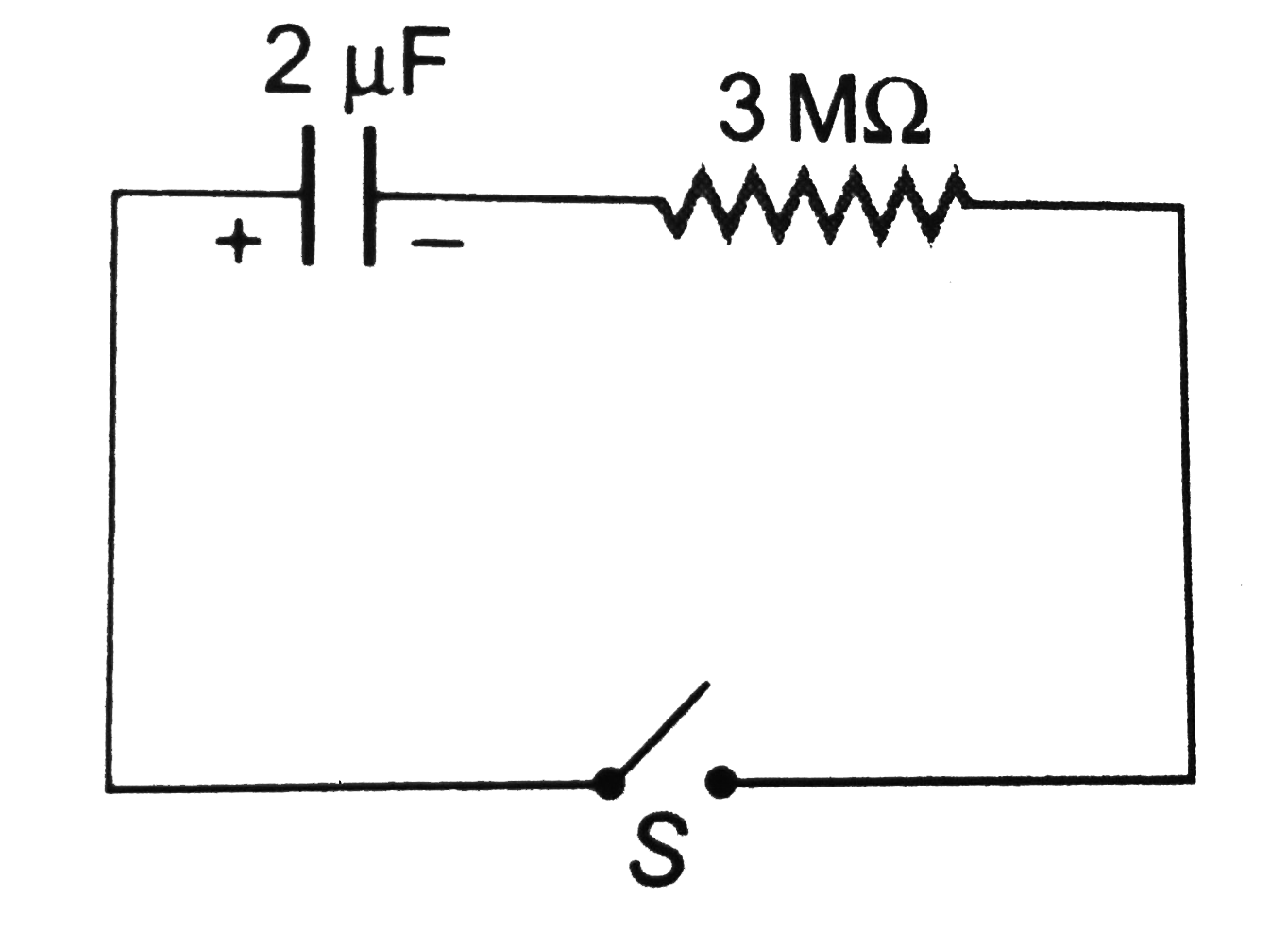
τc=CR=6s
q0=CV=10μC
Now,q=q0e−tτC=(10μC)e−126
=(16)2(10μC)
=(0.37)2(10μC)
EXAMPLE 4
In the circuit shown in figure, the capacitor is charged with a cell of 5V.If the switch is closed at t=0, then at t=12s, charge on the capacitor is

τc=CR=6s
q0=CV=10μC
Now,q=q0e−tτC=(10μC)e−126
=(16)2(10μC)
=(0.37)2(10μC)
EXAMPLE 5
A capacitor of capacity C is charged to a potential difference V and another capacitor of capacity 2C is charged to a potential difference 4V. The charged batteries are disconnected and the two capacitors are connected with reverse polarity (i.e. positive plate of first capacitor is connected to negative plate of second capacitor). The heat produced during the redistribution of charge between the capacitors will be
Total charge=(2C)(4V)−CV
=7CV
VC=Total chargeTotal capacitance
7CV2C+C=73V
Heat =Ui+Uf
=12CV2+12(2C)(4V)2−12×3C×(73V)2
=253CV2
SUMMARY
* A capacitor is a system of two conductors separated by an insulator. Its capacitance is defined by C=QV, where Q and –Q are the charges on the two conductors and V is the potential difference between them. C is determined purely geometrically, by the shapes, sizes and relative positions of the two conductors. The unit of capacitance is farad.For a parallel plate capacitor (with vacuum between the plates), C=ε0Ad.
* If the medium between the plates of a capacitor is filled with an insulating substance (dielectric), the electric field due to the charged plates induces a net dipole moment in the dielectric. This effect, called polarisation, gives rise to a field in the opposite direction. The net electric field inside the dielectric and hence the potential difference between the plates is thus reduced. Consequently, the capacitance C increases from its value C0 when there is no medium (vacuum), C=KC0 where K is the dielectric constant of the insulating substance.
* For capacitors in the series combination, the total capacitance C is given by
1C=1C1+1C2+1C3+..........+(1Cn)
In the parallel combination, the total capacitance C is:
C=C1+C2+C3+..........+Cn