MAGNETIC EFFECT OF ELECTRIC CURRENT for Class 10 PHYSICS
INTRODUCTION
Niche diye figure ko dekhiye aur bataiye ki Electric bell, Crane lifting iron junk, Bullet train and MRI machine in sb chijo me common kya hai? In sb me common ye hai ki ye sabhi magnetic effect of electric current ke according work karte hai jise electromagnetism bhi kehte hai, jiske baare me hum is chapter me study karenge.
Hum yaha pr different shape ke conductors ke around magnetic fields, electromagnets aur permanent magnets ki study karenge. Electricity me humne jo electric current ke baare me baat ki. Is electric current ke kuchh effects bhi hote hai, jaise ki heating effect, chemical effect aur magnetic effect. Jab kisi conducting wire se hum electric current pass karte hai, to ye wire ko heatup kr deta hai ise hi heating effect of electric current kahte hai jiska simple eg. hai electric bulb. Electric current ko kisi compound se pass karaya jata hai, ise simpler subtances me decompose karne ke liye jaise ki eg. electrolysis of water. Jab water se electric current pass karte hai to water ke compound hydrogen aur oxygen me divide ho jate hai. Electric current yaha pe electrolysis ka karan hai yahi chemical effect of electric current hai.
Is chapter me hum electric current ke magnetic effect pr hi focus karenge.
Magnetism ko ancient times se hi jana jata hai. Electricity 1700 me discover hua. Baad me 1820 me oersted naam ke scientist ne bht hi interesting phenomenon discover kiya. Jisme scientist ne ek wire aur ek magnetic compass use kiya. Wire ko magnetic compass ke pass rakha, jab is wire se koi current flow nahi karta hai tab magnetic compass normal apne north aur south direction me hota hai but jab wire se electric current flow karte hai to magnetic compass deflection show karta hai aur fr se electric current wire se flow karna band kr dete hai to magnetic compass normal north and south position me stable ho jata hai. Magnetic compass magnetic field se hi deflect hota hai isliye oersted ne ye conclusion diya ki wire electric current carry karta hai to wo magnet ki tarah behave karta hai, ek current carrying wire apne surrounding me magnetic field create karta hai yahi magnetic effect of electric current ya electromagnetism kehlata hai. Electric current ka magnetism produce karna ek magic ki tarah hai. Electromagnetism ki khoj se phle electricity aur magnetism ko seperately treat kiya jata tha but oersted ke experiment se ye maan liya gaya ki electricity aur magnetism aapas me linked hai. Electricity magnetism produce kr sakta hai. Kya magnetism bhi electricity produce kr sakta hai? Ha magnetism bhi electricity produce karta hai aur isi ka use karke electric generator se electricity generate kiya jata. Niche figure me bar magnet, magnetic needle and magnetic compass dikhaya gaya hai.

MAGNETISM
Magnetism bht purane time se hi jana jata raha hai. Magnet ek aisa object hai jo kai materials ko apni taraf attract karta hai jaise ki iron steel, nickel and cobalt.
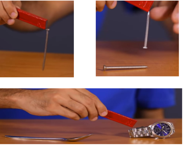
Ek magnet lete hai jinko kuchh material ke paas leja kr dekhte hai ki kya hota hai? Niche diye figure me aap dekhiye. Kisi magnet ko ager kisi nail ke pass le ja rahe ho to nail magnet ki taraf attract ho raha hai means ye nail iron ya steel ki bani hui hai. Jo nail magnet se attract nahi ho rahi hai wo stainless steel ke bane hote hai.
Ager hum kisi spoon ya watch ke pass magnet ko le jaye to ye materials magnet se attract nahi hote kyuki ye stainless steel se bane hue material hote hai.
Is tarah se hum magnets ko steel aur stainless steel me difference pata karne ke liye use kr sakte hai.
Magnets me do pole hote hai north pole and south pole. Hume kaise pata chalega ki koun sa end magnet me north ya south pole hai. Iska pata lagane ke liye hum magnet ko rassi se bandh kr freely suspend kr denge to magnet ka jo end north direction me rukega wo magnet ka north pole aur jo end south direction me rukega wo magnet ka south pole hai. Magnets different shapes ki bhi hote hai (shown in below figure).
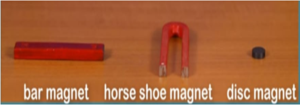
Rectangular shape ka magnet Bar magnet, U shape ka magnet horse shoe magnet aur chhota sa sikke ke jaisa magnet disc magnet kehlata hai.
Properties of magnet
1. Monopole cannot exist.2. Like poles repel each other.
3. Unlike pole attracts each other.
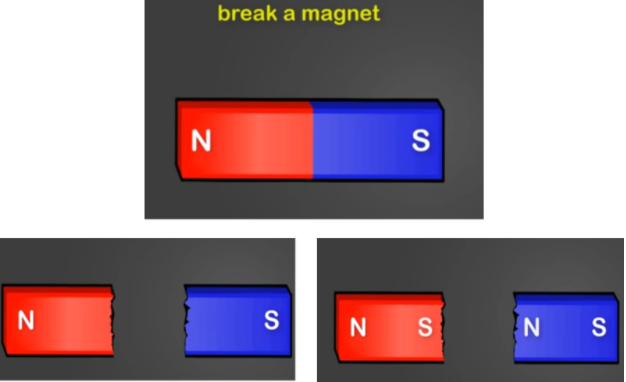
Kya kabhi magnet me single pole (monopole) ho sakte hai? Nahi, kisi bhi magnet me kabhi bhi single pole ya monopole exist nahi karte balki magnet me humesha do hi poles honge. Eg. ke liye ager hum kisi bar magnet ko do part me break bhi kr de to magnet ke each part me do pole honge. Again magnet ko jitne bhi tukdo me break karlo hr tukde me do pole north and south pole honge hi honge.
Like pole repel each other.
Do north pole ko pass lane se ek dusre ko repel karte hai isi tarah do south poles ko pass lane se bhi wo ek dusre ko repel karte hai.
Unlike pole attract each other.
North pole ko south pole ke pass lane se ek dusre ko attract karte hai.

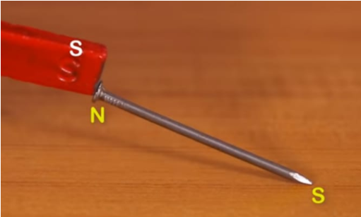
Jab magnets kisi iron nail ko attract karta hai to hota ye hai ki magnet ko iron nail ke pass lane se magnet pehle iron nail me opposite pole induce karta hai. Is tarah magnet ka south pole iron nail ke north pole ko attract karta hai. Isliye hum kah sakte hai ki induction ke karan attraction hota hai.
MAGNETIC FIELD AND FIELD LINES
Aapne gravitational field aur electric field ke baare me suna hoga. Field ka mtlb hota hai aisa koi area ya region jaha koi object, force experience karta hai. Eg. ke liye jaise ki kisi ball ko kuchh height tk le jane ke baad chhod dete hai to earth se kuchh gravitational force experience karne ke karan ball niche girta hai jo gravitational field present hone ke karan hota hai. Kisi magnet ke charo taraf magnetic field present hota hai, is magnetic field ke region me ager koi magnetic material aata hai to magnet se attract hota hai.Magnetic field - Ek current carrying conductor magnetic field produce karta hai. Magnetic field ka shape current carrying conductor ke shape pr depend karta hai jiske baare me hum discuss karenge. Current carrying conductors ya straight wire, circular loop ho sakte hai ya fr solenoid ho sakte hai.
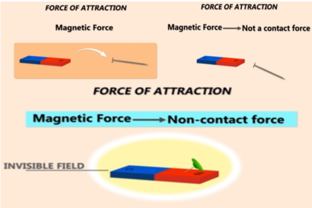
Jab koi magnetic material jaise ki iron ya steel kisi magnet ke magnetic field ke region me ata hai to ek force feel karta hai jise magnetic force kahte hai. Ye magnetic force attractive ya repulsive ho sakta hai. magnetic force, non contact force hai, jo kisi magnet ke charo taraf invisible magnetic field me kisi bhi magnetic material pr force lagata hai, jaisa ki niche diye gaye figure me dikhaya gaya hai.
Magnetic field ke region me kisi bhi magnetic material pr jo force of attraction apply hota hai wo strong ya weak ho sakta hai. Jaise ki aap apne mobile ko kisi wifi se ager connect karte hai to wifi ke pass ke region me aapko signal strong milta hai. Wifi se jaise jaise dur jate hai mobile me internet ka signal weak hota jata hai. Iska mtlb hai ki wifi ke paas ke region me strong signal hoga aur wifi ke dur ke region me signal weak hoga.
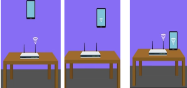
Wifi ke signal ki tarah hi magnet ke pass magnetic field strong hota hai aur jaise jaise dur jate hai vaise vaise magnetic field strength km hota jata hai.
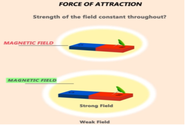
Magnetic field ko magnetic field lines se visualize karte hai. Magnetic field lines hume magnetic field ka shape batati hai.
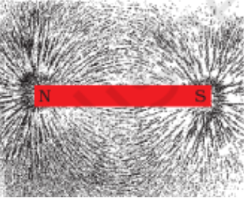
Magnetic field ka shape hum iron filling aur magnetic compass ke use se pata kr sakte hai.
Kisi paper ke uper bar magnet ko rakh kr iron filling ko magnet ke charo taraf sprinkle kr de fr gently paper ko tape kare to iron filling magnetic field lines ke shape me arrange ho jayegi aur kuchh aisi dikhai degi jaise niche figure me dikhaya gaya hai.
Magnetic field line ko plot karne ke liye other method hai magnetic compass ka use karke. Aapne jarur magnetic compass dekha hi hoga. Magnetic compass me magnetic needle hota hai jo tiny magnet se bana hota hai jo pivoted hota hai, jiske karan ye freely move kr sakta hai. Magnetic needle ka red part north pole hota hai jo earth ke north direction ko show karta hai. Magnetic needle ka other end south pole hota hai jo south direction ko show karta hai. Ager hum is magnetic compass ko move bhi karte hai to bhi apne north south direction me align rahata hai kyuki earth me magnetic field hota hai jo is magnetic needle ko uske direction me align karke rakhta hai.
Ye magnetic compass ko plotting compass bhi kahte hai. Bar magnet ke liye magnetic field lines draw karne ke liye hum magnetic compass ka use karte hai.
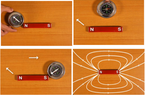
Center me hum bar magnet rakhte hai jisme magnetic compass ko magnet ke north pole ke pass rakhte hai. Magnetic field ki direction wo hogi jis direction me magnet ka north pole force experience karta hai.
Niche figure me aap dekh sakte ho ki magnet ka north pole compass ke north pole ko dur push karta hai jis direction me compass ka north pole hai wo bar magnet ke liye magnetic field ki direction hogi. Ab hum compass ko bar magnet ke side me rakhenge to fr se magnetic needle ki north direction bar magnet ke liye magnetic field ki direction ko show kr rahi hai to hum ise draw kr lete hai. Ab hum compass ko bar magnet ke south pole ke side rakhte hai to magnetic needle ki direction bar magnet ke south pole ke towards hoti hai. In lines ko hum join kr de to hume curved line milegi jo magnetic field line hai. Is process ko hum thode-thode distance me repeat karte hai to hume niche dikhaye gaye figure ki tarah hi magnetic field lines mil jayegi. Hum magnetic field line ki direction ko arrow se show karte hai. Is tarah se magnetic field lines ki direction magnet ke outside me north pole se south pole ki taraf hoti hai.
Horse shoe magnet ke liye magnetic field line ki direction kuchh is tarah se hoti hai.
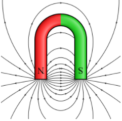
Is prakar magnetic field lines ki shape magnets ke shape ke uper depend karti hai.
Properties of magnetic field
Magnetic field lines ki properties discuss karne ke liye hum bar magnets ka use karenge.1. Magnetic field lines magnet ke north pole se start hoti aur south pole me end hoti hai.
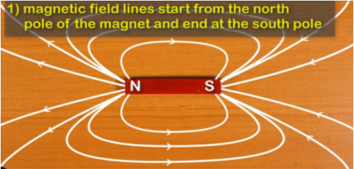
Direction of magnetic field lines shown by the arrow. Outside of the bar magnet direction magnetic field lines ki direction north pole se south pole ki taraf hoti hai. Bar magnet ke ander magnetic field lines ki direction south pole se north pole ki taraf hoti hai.
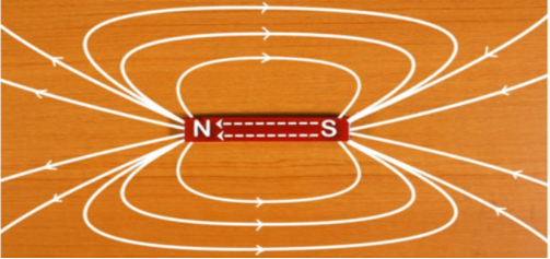
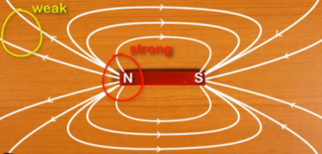
2. Jab magnetic field lines pass-pass hote hai to ye show karte hai ki magnetic field yaha pe strong hai. Jaha pr magnetic field lines dur dur hote hai to ye show karte hai ki magnetic field yaha pr weak hai.
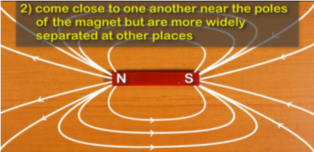
Niche figure me aap dekh sakte ho ki magnet ke jitna paas jate hai utna hi magnetic field lines ek dusre ke closer hai. Wahi ager magnet se jitna dur jate hai magnetic field lines dur dur hai.
3. Magnetic field lines ek dusre ko kabhi cross nahi karti. Magnetic field line ek dusre ke pass-pass to aa sakti hai but ek dusre ko kabhi cross nahi karti.
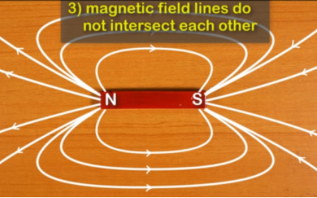
Maan lo ager two magnetic field lines ek dusre ko intersect karegi. Yaha hum magnetic compass rakh de to ye compass koun se magnetic field line ki direction ko show karegi? Magnetic field lines ki do alag alag direction possible hi nahi hai. Isliye ye bhi possible nahi ho sakta ki magnetic field lines ek dusre ko cross kare.
POINT 1
Magnetism :
Magnetism, phenomenon associated with magnetic fields, which arise from the motion of electric charges.
Magnetic Field :
The magnetic field is a region or space where there is an influence of a magnet.
Magnetic Field Lines :
Magnetic field lines are imaginary lines around the magnet.
EXAMPLE 1
A current through a horizontal power line flows in east to west direction. What is the direction of the magnetic field at a point directly below it and at a point directly above it?
The current is in the east-west direction. Applying the right-hand thumb rule, we get that the magnetic field (at any point below or above the wire) turns clockwise in a plane perpendicular to the wire, when viewed from the east end, and anti-clockwise, when viewed from the west end.
EXAMPLE 2
A coil of insulated copper wire is connected to a galvanometer. What would happen if a bar magnet is
(i) pushed into the coil?
(ii) withdrawn from inside the coil?
(iii) held stationary inside the coil?
(i) The magnetic flux linked with the coil changes (i.e., increases). As a result of this, an induced current flows in the coil and the galvanometer shows a momentary deflection (say towards right) i.e., the needle of the galvanometer moves momentarily in one direction.
(ii) The magnetic flux linked with the coil changes (i.e., decreases). As a result of this, an induced current flows in the coil but in a direction opposite to that in case (i). Obviously, the galvanometer momentary shows a deflection in the opposite direction (i.e., towards left) i.e., the needle of the galvanometer moves momentary but in the opposite direction to (i).
(iii) When the magnet is held stationary in the coil, there will be a magnetic flux in the coil but it will remain constant. Since the magnetic flux does not change, there is no induced current in the coil and the galvanometer shows no deflection.
EXAMPLE 3
A magnetic compass needle is placed in the plane of paper near point A as shown in figure. In which plane should a straight current carrying conductor be placed so that it passes through A and there is no change in the direction of the compass? Under what condition is the deflection maximum and why?
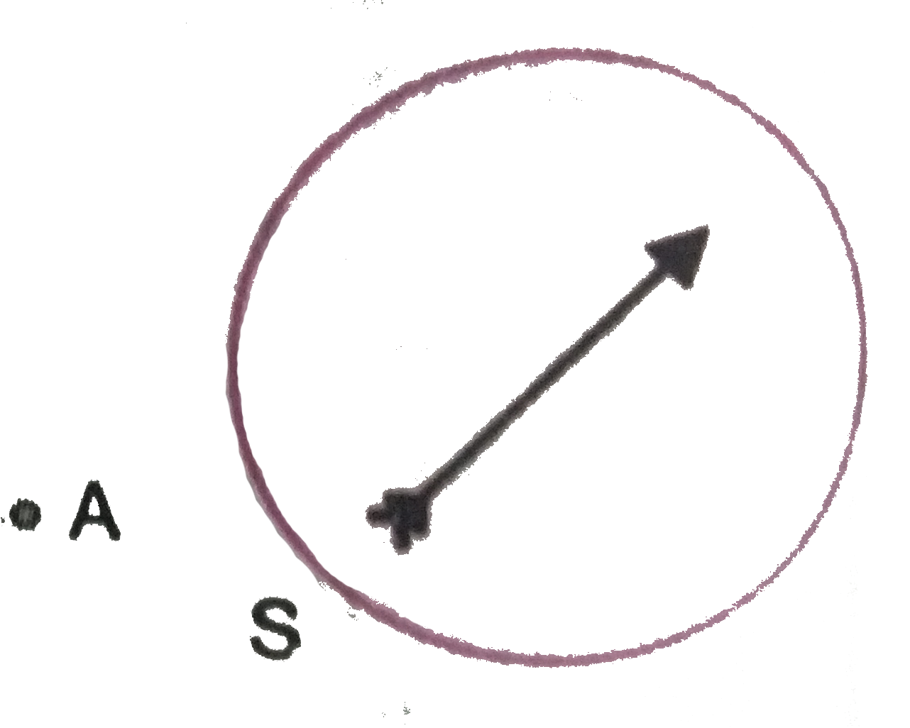
If there is to be no change in the deflection of the compass, the magnetic field due to the current-carrying conductor should be perpendicular to the plane of the paper. For this, the conductor should lie in the plane of the paper. (In this case, the magnetic field due to the current-carrying conductor is along the axis of the compass, i.e., in the vertical direction). The deflection is maximum when the conductor through A is perpendicular to the plane of the paper because in this case, its magnetic field is maximum in the plane of the paper.
EXAMPLE 4
An electron enters a magnetic field at right angles to it, as shown in Fig. The direction of force acting on the electron will be (a) to the right. (b) to the left. (c) out of the page. (d) into the page.
Answer is option (d). The direction of force is perpendicular to the direction of magnetic field and current as given by Fleming’s left hand rule. Recall that the direction of current is taken opposite to the direction of motion of electrons. The force is therefore directed into the page.
EXAMPLE 5
State Right-Hand Thumb Rule to find the direction of magnetic field around a straight conductor carrying current. How will this magnetic field be affected:
(a) increasing the current through the conductor,
(b) changing the direction of flow of current through the conductor?
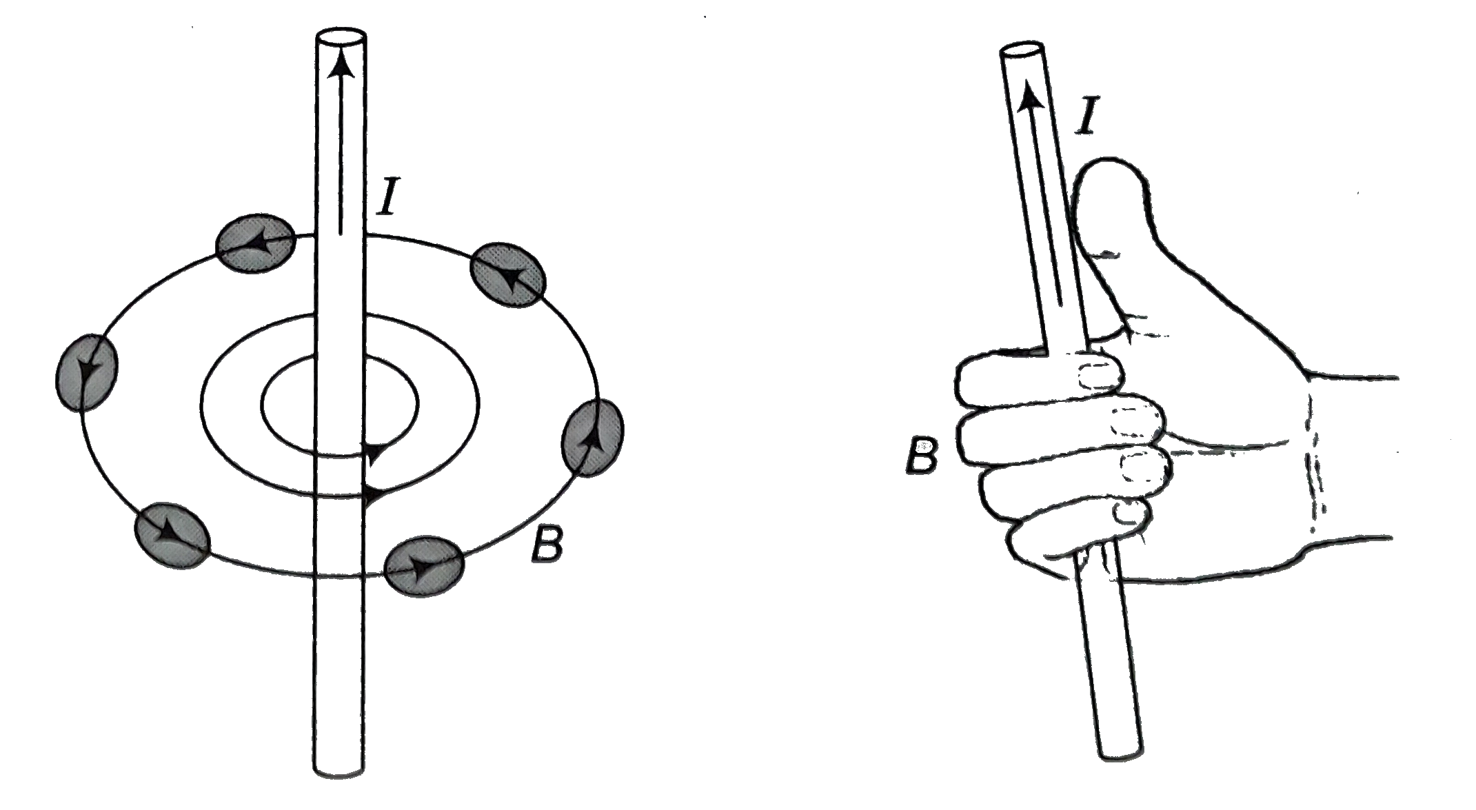
Hold the straight conductor in your right hand such that the thumb points out in the direction of flow of current. The direction of curling of the fingers gives the direction of the magnetic field lines around the conductor.
(a) increasing current through the conductor increases the strength of the magnetic field.
(b) changing the direction of flow of current through the conductor changes the direction of the magnetic field. However, the strength of the magnetic field remains the same.
EXAMPLE 6
The magnetic field in a given region is uniform. Draw a diagram to represent it.
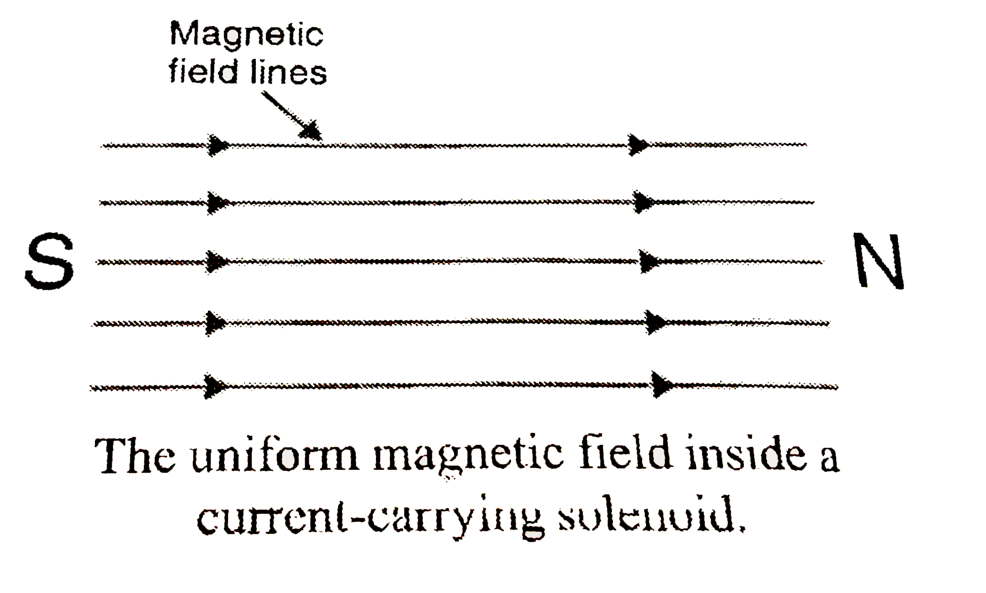
A uniform magnetic field in a region is represented by drawing equidistant, parallel straight lines, all pointing in the same direction. For example, the uniform magnetic field which exists inside a current-carrying solenoid can be represented by parallel straight lines pointing from its S-pole to N-pole (as shown in Figure alongside).
EXAMPLE 7
A steam of positively charged particles (alpha particles) moving towards west is deflected towards north by a magnetic field. The direction of magnetic field is :
(a) towards south
(b) towards east
(c) downward
(d) upward
Here the positively charged alpha particles are moving towards west, so the direction of current is towards north, so the force is towards north. So, we are given that :
(i) direction of current is towards west, and
(ii) direction of force is towards north.
Let us now hold the forefinger, centre finger and thumb of our left-hand at right angles to one another. Adjust the hand in such a way that our centre finger points towards west (in the direction of current) and thumb points towards north (in the direction of force). Now, if we look at our forefinger, it will be pointing upward. Since the direction of the forefinger gives the direction of the magnetic field, therefore, the magnetic field is in the upward direction. So, the correct answer is : (d) upward.
EXAMPLE 8
Why does a magnetic compass needle pointing north and south in the absence of a nearby magnet get deflected when a bar magnet or a current loop is brought near it ? Describe some salient features of magnetic lines of field concept.
When a magnetic compass needle pointing north and south in the absence of a nearly magnet or a current loop, it is action upon by the earth's magnetic field only. But in the presence of a magnet or a current loop (which also has a magnetic field ) the earth's magnetic field near to the compass is modified and the needle is deflected from north and south directions.
(i) A magnetic field line is directed from north-pole to south -pole outside the magnet. ltbr (ii) A magnetic field line a closed and continuous curve
(iii) The magnetic field lines never intersect each other, because if two lines meet, it means that force is acting in two directions at that point which is not possible.
(iv) Closer the field , stronger is the magnetic field and vice-versa is also true.
(v) Magnetic field lines are parallel and equidistant, those represent a uniform magnetic field.
MAGNETIC FIELD DUE TO A CURRENT-CARRYING CONDUCTOR
Magnetic Field due to a Current through a Straight Conductor
Ek straight wire me jab koi current flow nahi hota to uske charo taraf koi field nahi hota but jab is wire se current flow karte hai to uske charo taraf magnetic field create hota hai aur ye magnetic field shape me circular hota hai jaisa ki niche diye gaye figure me show kiya gaya hai. Ye magnetic field lines wire ke around concentric circles hote hai. Ise easily samjhne ke liye ek plane le lete hai jo straight current carrying conductor ke perpendicular hai, is plane me magnetic field lines concentric circles ke forms me lie karti hai.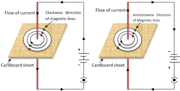
Ager hum straight conductor ke around magnetic field line ka pata lagana chahe to uske liye hum iron filling aur magnetic compass ke help se pata laga sakte hai. Aap figure me dekh sakte hai ki magnetic field line ek particular direction me hai.
Right-Hand Thumb Rule
Jaisa ki humne dekha ki magnetic field lines certain direction me hoti hai joki figure me arrow se mark kiya hai. Is direction ko hi find out karne ke liye hum Maxwell’s right hand thumb rule ka use karte hai. Niche figure me dikhaye anusar apne hath ko hold karenge to thumb ki direction current ki direction ko show karti hai aur fingers jis direction me curl karti hai wo magnetic field ki direction ko show karti hai. Yaha pr figure me current downward direction me hai to magnetic field lines ki direction clockwise direction hai iske opposite ager current upward direction me ho to to magnetic field ki direction anticlockwise direction me hogi. Yahi right hand thumb rule hai jo hr electromagnetic field ke liye applicable hai.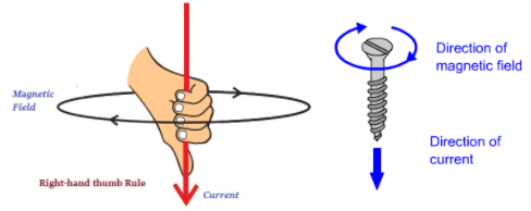
Strength of the magnetic field is inversely proportional to the distance of wire. Ager kisi current carrying wire se jitna jyada distance hoga utna weak magnetic field hoga.
Magnetic Field due to a Current through a Circular Loop
Circular loop ke karan magnetic field ke effect ko dekhne ke liye hum ek straight conductor ko hi circular form me bend kr dete hai. Ab is loop se jab current pass karte hai to ye loop ke around magnetic field create karte hai. Circular loop ke liye magnetic field straight wire ke liye magnetic field se jyada strong hote hai. Is loop ke liye magnetic field line ki shape ko find out karne ke liye hum circular loop ke small straight segment ko consider karte hai to ye segments straight current carrying conductor ki tarah circular magnetic field create karte hai. Jaise ki niche diye gaye figure me aap dekh sakte hai ki jis wire ke part ke liye hum magnetic field lines dekh rahe hai usse jaise jaise dur le jate jaye to magnetic field line dur dur hoti jati hai aur is circular loop ke center me magnetic field lines ki shape straight hoti hai. Ab in magnetic fields ki direction ko find out karne ke liye loop ke alag alag segments ke pass hum right hand thumb rule ka use karenge to hume magnetic field lines ki direction mil jayegi. Jaise ki yaha figure me circular loop ke right segment ke liye current ki direction downward hai to magnetic field line ki direction hume clockwise mil rahi hai, wahi ager loop ke left side current ki direction upward hai hume magnetic field line ki direction anticlockwise mil rahi hai. Ye saari magnetic field line loop ke center me addup ho rahi hai isliye ye strong magnetic fields create karti hai. Ager hume is magnetic fields ki strength ko increase karni ho to iske liye hum loop se electric current ki values ko increase kr sakte hai.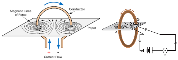
Is circular current carrying loop magnetic field create kr raha hai mtlb is loop ke liye north pole aur south pole bhi present honge. Ab is current carrying loop ke liye polarity find out karne ke liye hum clock phase rule ka use karenge. Is rule ke according ager circular loop me current ki direction clockwise ho to jis face se hum loop me current ki direction dekh rahe hai udhar south pole hoga aur ager loop me current ki direction anticlock wise ho to jis face se hum loop me current ki direction ko anticlockwise dekh rahe hai us face me north pole hoga.
- Anticlockwise me n letter se aap yaad rakh sakte hai ki loop me anticlockwise current ke liye north pole hoga.
Magnetic Field due to a Current in Solenoid
Solenoid is a long coil made up of insulated copper wire containing a large number of turns. Kisi long conducting insulated wire ko ager coils ke form me lapet de jisme bht sare number of turns ho to ye solenoid ban jata hai. Jab is solenoid se electric current pass hota hai to solenoid ka hr ek turn a current carrying circular loop ki tarah behave karta hai. Isliye each circular loop iske around the magnetic field produce karta hai. Each circular current carrying loop ka magnetic field add up ho jata hai aur solenoid ke around bht hi strong magnetic field create karta hai. Solenoid ke dwara produce kiye ja rahe magnetic field ka shape, bar magnet ke dwara produce hone wale magnetic field ke shape similar hota hai. Bar magnet ke two poles north pole and south pole bar magnets ke end me hota hai, isi tarah solenoid me bhi two poles honge. Ab yaha pe hume determine krna hai ki solenoid ke kis end me koun sa pole hoga. Kyuki solenoid many circular loops se milkar bana hai aur circular loop me poles determine karne ke liye hum clock face rule ka use karte hai. Isliye hum solenoid me clock face rule ka use karke pole determine karne ke liye solenoid ke right side se dekhe to current ki direction hume clock wise dikhegi, jiska mtlb hai jis end se hum clockwise current ko dekh rahe hai solenoid ka wo end south pole hoga. Solenoid ke other end means left end se circular loops me current ki direction ko dekhne pr current anticlockwise direction me dikhega means is end me north pole hai.A b humne solenoid ki polarity ko check karne ke liye clockface rule ka use kiya, iske alawa hum magnetic compass aur bar magnet ko bhi solenoid ki polarity check karne ke liye use kr sakte hai. Kyuki two like poles ek dusre ko repel karte hai aur two unlike poles ek dusre ko attract karte hai isliye ager hum kisi bar magnet ke north pole ko solenoid ke kisi ek end ki taraf lane se ager repulsion hota hai means wo end solenoid ka north pole hai aur ager attraction hota hai means wo end solenoid ka south pole hai.
Solenoid ke inside me create hone wali magnetic field lines straight lines hoti hai jo solenoid ke ander hr point pr equally distribute hoti hai isliye solenoid ke ander magnetic field uniform magnetic field hota hai.
Solenoid ki magnetic field strength ko change karne ke 3 tarike hai.
1. Solenoid me flow hone wale current ki strength ko badha diya jaye to solenoid ki bhi strength badh jayegi.
2. Solenoid me present coils ke number of turns ko increase karke bhi solenoid ki strength ko increase kr sakte hai.
3. Ager solenoid ke ander soft iron core ko rakh diya jaye to is soft iron core ko easily magnetise hone ki property ke karan solenoid ki magnetic field strength increase ho jayegi. Solenoid aur soft iron core ka combination electromagnet kehlata hai.
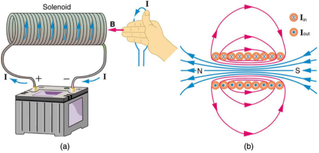
Electromagnets, permanent magnets se different hota hai. Permanent magnets regular magnets hote hai jiska use hum fridge magnets, toys, microphones, loudspeakers me karte hai.
Permanent magnets steel and alloys se milker bante hai jaise ki carbon steel, chromium steel ya alnico. In sb se bane permanent magnets usually normal steel se jyada strong hote hai.
Electromagnets long insulated copper wire ko kisi soft iron core ke uper lapet ke banaya jata hai. Current is copper wires se pass hote hai. Electromagnet ke various applications hai electric bells, a crane lifting iron junk and MRI machines.
Difference Between Electromagnets and Permanent Magnets
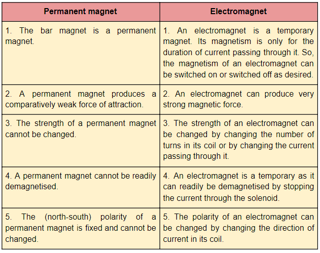
FORCE ON A CURRENT-CARRYING CONDUCTOR IN A MAGNETIC FIELD
Magnetic field, kisi conductor me current ke flow se us conductor ke around create hua. Is magnetic field me ager koi magnet rakha ho to wo is current carrying conductor ke karan force feel karega. French scientist Ampere ke according magnetic field me rakhe magnet ke dwara bhi current carrying conductor pr equal and opposite force lagta hai. Ise hum ek activity ke dwara samjhenge jisme current carrying conductor ke magnetic field me rakhe magnets ke dwara usi current carrying conductor me force lagega.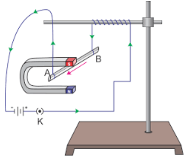
Iske liye hume ek small aluminium rod AB chahiye jo lagbhag 5 cm ki ho. Ise horizontally two connecting wire se attach karke latka denge jaisa uper figure me dikhaya gaya hai. Ek horse shoe magnet lenge jise aise place karenge ki is magnet ke dono poles ke bich aluminium ki rod aae aur magnetic field ki direction directely upward ho. Magnet ka north pole vertically rod ke niche aur south pole vertically rod ke uper honi chahiye. Rod ke sath series me battery aur rheostat connect karenge. Hum aluminium ki rod me B to A current flow karaenge. Aap dekhenge ki rod left direction ki taraf move krega aur ager current ki direction ko reverse kr de to rod right direction ki taraf move karega. Hum yaha se conclude kr sakte hai ki, jab kisi current carrying aluminium rod ko kisi magnetic field me place karte hai to rod me force exert hota hai.
Direction of force current ki direction ke opposite direction me hota hai. Ager hum magnet ki poles ko interchange kr de to current carrying conductor me lagne wale force ki direction bhi change ho jayegi.
Isse ye prove hota hai ki force ki direction magnetic field aur current ki direction pr depend karti hai. Ager current ki direction magnetic field ke perpendicular ho to force ka magnitude highest hota hai. Fleming’s left hand rule se hum is force ki direction ko find karte hai.
Fleming's left hand rule se force ki direction find karne ke liye apne thumb, fore finger aur center finger ko ek dusre ke sath right angles pr rakhiye jaise figure me dikhaya hai. Fore finger direction of magnetic field ko show karta hai. Yaad rakhne ka easy way hai f for forefinger f for field. Center finger current ko represent karta hai jise c for center finger aur c for current se yaad rakh sakte ho. Thumb, force ke direction ko represent karta hai.
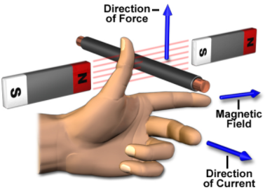
Ab dekhenge ki hum Fleming’s left hand rule ko magnetic field ke bich rakhe current carrying conductor me lagne wale force ka direction find out karne ke liye kaise use kr sakte hai.
Magnetic field ki direction north se south ki taraf hoti hai to fore finger ko magnetic field ke direction me place kariye fr current ki direction ko dekhiye aur center finger ko current ke direction me rakhiye to thumb hume force ki direction provide kr dega.
Electric motors, electric generators, loud speakers, microphones ye sb examples hai jisme magnetic field ke bich current carrying conductor ka use kiya jata hai.
POINT 2
Maxwell’s Right Hand Thumb Rule:
The direction of the current is given by Maxwell’s right-hand thumb rule, “If the current carrying conductor is gripped with the right hand in such a way that the thumb gives the direction of the current, then the direction of the fingers gives the direction of the magnetic field produced around the conductor.
Clock Face Rule :
When an observer, looking at the face of the coil, finds the current to be flowing in the anti-clockwise direction, then the face of the coil will behave like the North Pole. While if the current is in the clockwise direction, the face of the coil will behave like the South Pole.
Flemings Left Hand Rule :
Stretch the thumb, forefinger and middle finger of the left hand such that they are mutually perpendicular. If the forefingers is in the direction of the magnetic field, middle finger in the direction of current then thumb will point in the direction of motion or force.
Solenoid :
Solenoid is defined as coil of many circular turns of insulated copper wire wrapped closely in a cylindrical form.
Electromagnet :
It is temporary magnet that can be easily demagnetized. In this type of magnet, polarity can be reversed and strength can be varied. They are very strong magnet.
Permanent Magnet :
These types of magnet cannot be easily demagnetized. They are weak magnets in which polarity cannot be reversed.
EXAMPLE 9
A current-carrying straight conductor is placed in the east-west direction. What will be the direction of the force experienced by this conductor due to the Earth's magnetic field? How will this force get affected on:
(a) reversing the direction of flow of current,
(b) doubling the magnitude of current?
The direction of the Earth's magnetic field is from geographic south to north. Let the direction of current in the conductor be from west to east. Applying Fleming's left-hand rule, we find, that the direction of the force acting on the conductor will be vertically upwards,
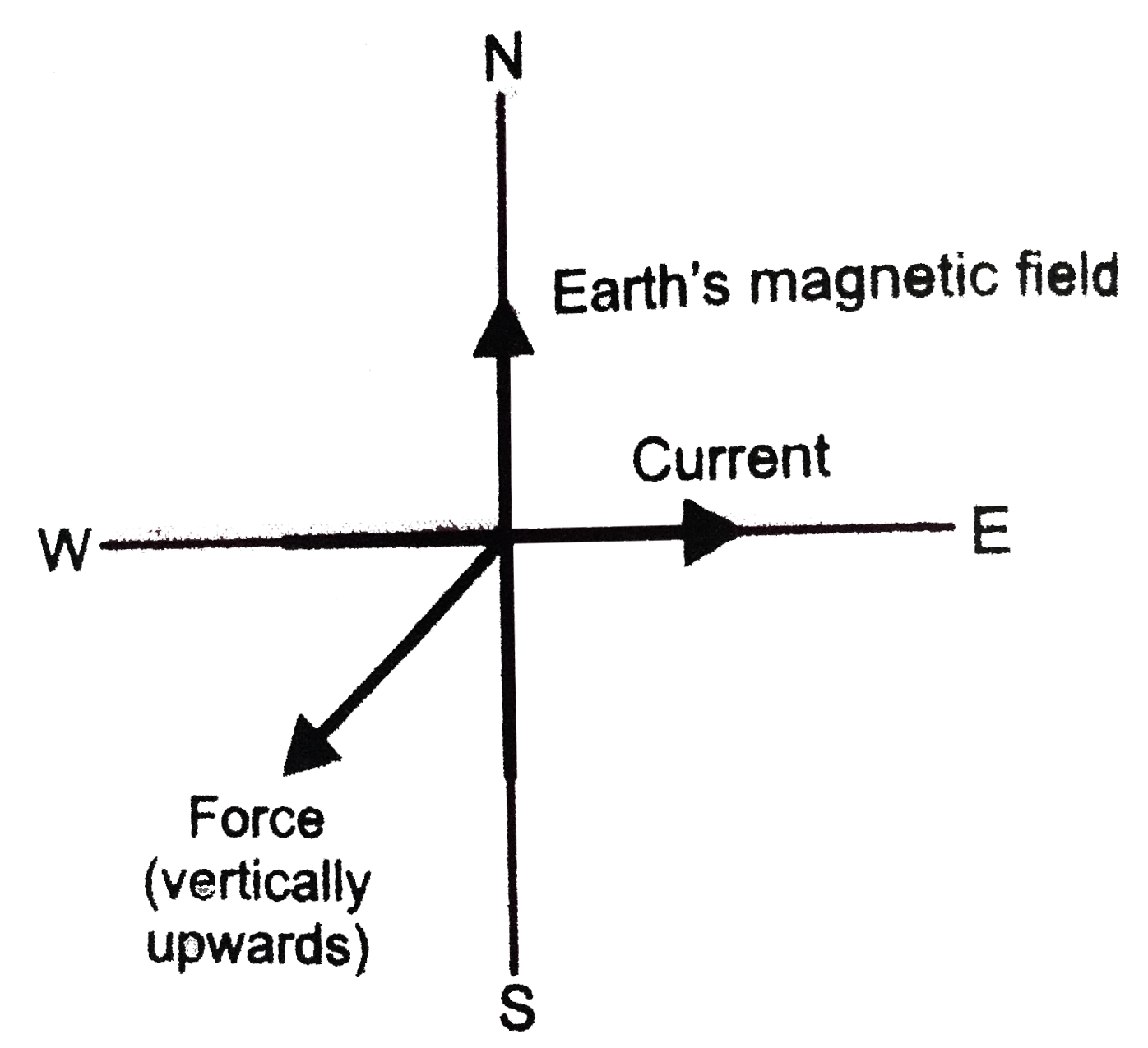
(a) By reversing the direction of current (i.e., making it flow from east to west, the direction of force experienced by the conductor will be reversed, i.e., it will now act vertically downwards.
(b) The magnitude of the force is doubled (as F∝I).
EXAMPLE 10
Think you are sitting in a chamber with your back to one wall. An electron beam moving horizontally from the back wall towards the front wall towards the front wall is deflected by a strong magnetic field to your right side. What is the direction of magnetic field ?
Here the electron beam is moving from our back wall to the front wall, so the direction of current will be in the opposite direction, from front wall towards back wall towards back wall or towards us. The direction of deflection (or force) is towards our right side. We now know two things :
(i) direction of current is from front towards us, and
(ii) direction of force is towards our right side.
Let us now hold the forefinger, centre finger and thumb of our left hand at right angles to one another. We now adjust the hand in such a way that our centre finger points towards us (in the direction of current) and thumb points towards the right side (in the direction of force). Now, if we look at our forefinger, it will be pointing vertically downwards. Since the direction of the forefinger gives the direction of the magnetic field, therefore, the magnetic field is in the vertically downward direction.
EXAMPLE 11
AB is a current carrying conductor in the plane of the paper as shown in figure. What are the directions of magnetic fields produced by it at points P and Q ? Given r1>r2, where will the strength of the magnetic field be larger ?
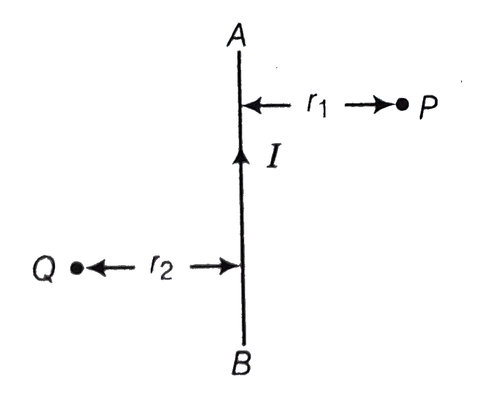
In the given figure, the current carrying conductor AB is in the plane of the paper. Thus, the direction of magnetic field is into the plane of the paper at P and Q. The magnitude of magnetic field B is inversely proportional to distance r
i.e., B∝1r
Magnetic field B is stronger near the conduct at Q at P as r1>r2.
EXAMPLE 12
A magnetic compass shows a deflection, when placed near a current carrying wire. How will the deflection of the compass get affected, if the current in the wire is increased? Support your answer with a reason.
A magnetic compass show a deflection, when placed near a current carrying wire as shown in the figure
This deflection of the compass increases because the magentic field B due to current carrying straight conductor is directly proportional to the strength of the current I passing through it. It is expressed as
B∝I
If the current is increased then the magnetic field produced is stronger and vice-versa.
EXAMPLE 13
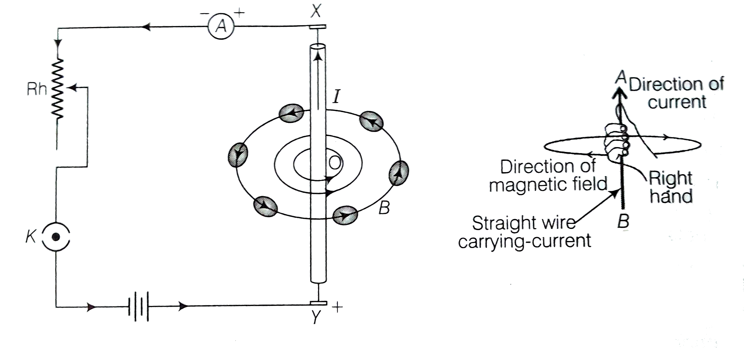
With the help of a labelled circuit diagram illustrate the pattern of field lines of the magnetic around a current-carrying straight long conducting wire. How is the right hand thumb rule useful to the direction of magnetic field associated with a current-carrying conductor?
Take a thick straight conductor XY and pass it through the centre of a thick cardboard. Connect the ends of the conductor to the terminals of a battery through a Rheostat Rh, a key K and and ammeter (A) so that current flows from Y to X , when we sprinkle some iron fillings on the cardboard, these average themselves in concentric circles around O when cardboard is gently tapped.
Thus, the pattern of concentric circles indicating the field line of a magnetic field is observed. These concentric circles represent the magnetic field around a current carrying straight wire becoming larger and larger as we move away from it.
We use the right thumb rule to find the direction of the magnetic field. if follows as imagine the straight conductor in your right hand such that the thumb points in the direction of current
Then, the direction of asking of fingers of the right hand gives the direction of magnetic field lines.
EXAMPLE 14
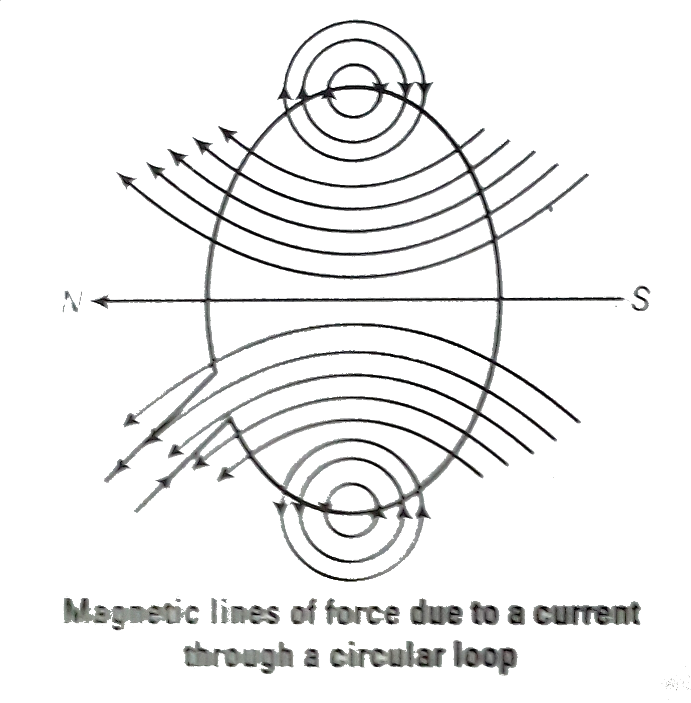
Explain with the help of a labelled diagram the diagram the distribution of magnetic field due to a current through a circular loop. Why is it that if a current carrying coil has n turns the field produced at any point is n times as large as that produced by a single turn?
The magnetic field pattern due to a circular coil is shown in the given figure. At every point of the current carrying circular loop the concentric circles representing the magnetic field around it becomes larger and larger as we move away from the wire. At the centre of the loop the field appears as straight line
The magnetic field proeduced by current carrying circular wire at a given point , depend on
(i) Amount of current flowing through the wire The strength of magnetic field (B) due to current carrying circular wire is directly proportional to the amount of current (I) flowing through it.
i.e., B∝I
(ii) Number of turns of the circular wire The strength of the magnetic field due to current carrying wire is directly proportional to the number of turns (N) of the wire.
i.e., B∝N
If there is a circular coil having n turns, field produced is n times as large as that produced by a single turn. It happens because the current in each circular turn has the same direction and the field due to turn just adds up.
EXAMPLE 15
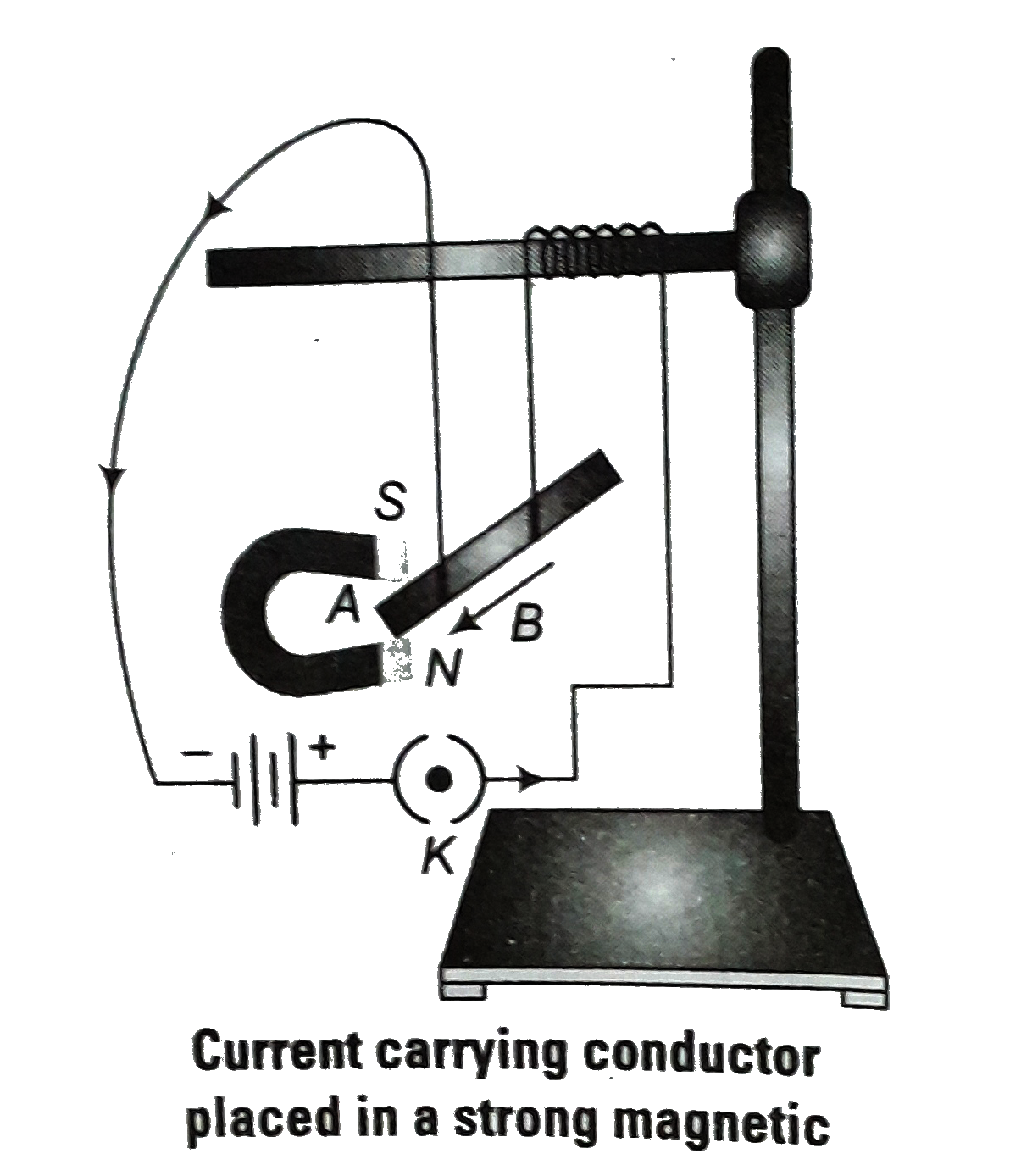
Describe the activity that shows that a current-carrying conductor experiences a force perpendicular to its length and the external magnetic field. How does felming's left-hand rule help us to find the direction of the force acting of the current-carrying conductor?
Aim To show that force is exerted on a current carrying conductor placed in a strong magnetic field.
Materials Required
A conducting rod (AB), connecting wires, horse shoe magnet, battery, switch and clamp stand.
Procedure
(i) Connect the conducting rod AB to the battery and key.
(ii) Place a strong horse shoe magnet in such a way that the rod AB lines between the poles with magnetic field directed upwards, i.e., N-pole is vertically above the rod.
(iii) Plug in the key.
Observation
A current-carrying rod AB experiences a force perpendicular to its length and the magnetic field.
Based on above observation, it can be said that when a current carrying conductor is placed within a magnetic field, the conductor experiences deflection. Fleming's left hand rule explains the direction of displacement in this case. Let us assume that the current is moving in anticlockwise direction in the loops. It that case, the magnetic field would be in clockwise direction at the top of the loop. Moreover, it would be in an anticlockwise direction at the bottom of the loop.
ELECTRIC MOTOR
Kya aap jante hai ki toy car move koun karata hai. Isme electric motor laga hota hai jo toy car ko move karata hai. Electric motors bht sare places me use hota jaise ki toys, fans, washing machines, mixers and grinders.
Principle - Electric motor ka is principle pr base hota hai jab kisi current carrying conductor ko kisi magnetic field me rakh de to conductor, force experience karta hai.
When a current carrying conductor is placed in a magnetic field it experiences a force.
Humne straight current carrying wire ke karan magnetic field ke baare me baat ki is magnetic field ke pass koi magnetic compass rakh dene se compass me deflection show krta hai. Kya iska reverse bhi possible hai? Kya kisi magnet ke karan current carrying conductor me force lg sakta hai? Ha... aisa possible hai magnets ke bich rakhe current carrying wire me magnets ke wajah se force lagta hai aur ager ye wire move karne ke liye free hai to wire move bhi karta hai. Newton’s third law yaad kijiye jiske according hr action ka equal aur opposite reaction hota hai. Aisa hi koi current carrying wire magnetic compass pr force laga raha hai usi tarah equal and opposite force magnetic compass bhi current carrying wire pe lagayega. Other way me hum ye bhi kah sakte hai ki koi current carrying wire ek magnet ki tarah behave karta hai isliye kisi magnetic compass aur current carrying wire ke bich do magnets ki tarah attraction ya repulsion hoga. Magnets ka behaviour ki koi current carrying conductor magnetic field me rakha ho to wo force experience karta hai, ye 1821 me Michael Faraday ke dwara khoja gaya. Ager is wire me koi current nahi hoga to magnets ke bich rakhe jane ke baad bhi ye wire koi force experience nahi karta. Yaha interesting baat ye hai ki koi current carrying wire maximum force experience karta hai jab ye magnetic field ke perpendicular rakha ho. Ager yahi current carrying conductor magnetic field ke parallel rakha ho to koi force experience nahi karta. Ager ye current carrying conductor magnetic field ke inclined rakha ho to kuchh force experience karta hai.
Maximum force experience karne ke liye current carrying conductor ko magnetic field ke perpendicular rakha jana chahiye.
Is current carrying conductor me lagne wala force three factors pe depend karta hai.
Force is directly proportional to the strength of the magnetic field (B).
Force is directly proportional to current (I).
Force is directly proportional to length of the wire (l).
Tino ko combine karne pr
F∝BIl
F=KBIl
In SI unit K=1 then F=BIl
Yaha se hum magnetic field B ke liye unit find kr sakte hai.
B=FIl
SI unit of B=NAm
ya Tesla(T)
magnetic field ka ek aur unit weber/m2 bhi hota hai.
Direction of the force - Magnetic field me rakhe current carrying conductor ka direction find out karne ke liye hum Fleming's left hand rule ka use karte hai.
Ab hum dekhenge ki ye principles electric motor me kaise apply hote hai. Electric motor jin applications me use hota hai jaise ki fan toy grinder in sabhi me ye rotational motion produce karta hai.
In sb me electric motor jis form me energy ko use karta hai wo hai electrical energy aur in sb me jis form me energy ko convert karta hai wo hai mechanical energy ya rotational kinetic energy. Iska mtlb hai electric motor ek device hai jo electrical energy ko mechanical energy me convert karta hai. Hum DC motor ke baare me discuss karenge jisme electric motor direct current ke form me work karta hai. Direct current ka mtlb hai ki current kevel one direction me flow karta hai.
Electric motor rotational motor produce karta hai jiske liye do taraf se equal aur opposite force ka lagna jaruri hota hai jise couple bolte hai ye couple force hi electric motor me rotation motion provide karta hai. Electric motor isi concept pr design hota hai. Electric motor me straight wire use karne ki jagah rectangular coil use karte hai. Jisse two equal aur opposite force coil ke two sides me apply hote hai aur rotational motion produce hote hai. Is prakar electric motor me rotational motion produce hota hai jab magnetic field me rakhe rectangular coil se current pass karaya jata hai to coil me force act karta hai aur ise continuously rotate karta hai. Niche diye gaye figure me dekhiye ki electric motor kis tarah se banta hai.
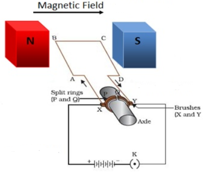
Magnets ke bich magnetic field north to south hota hai jisme ek rectangular coil rakhi hui hai. Isme ABCD mark kiya gaya hai, jise armature coil kahte hai. Current ko right direction me flow karane ke liye ek device ki jarurt hoti hai jise commutator kahte hai jisme two copper se bane half rings hote hai jise split rings kahte hai. Rectangular coil ke two ends is split rings se joined hote hai. Commutator and rectangular coil ke bich ek shaft hota hai jo rotate hota hai. Electric motor ko run karne ke liye hume voltage supply ki jarurat hoti hai. Voltage supply battery se diya jata hai jisme ek ya more cells hote hai. Ager rectangular coil ke wire battery ke wire se directly connect honge to to rectangular coil twist ho jayenge ise avoid karne ke liye carbon brushes ka use kiya jata hai. Carbon brush battery ke wire aur rotating commutator ke bich contact ko maintain karta hai. Kyuki ye carbon brush good conductors hote hai isliye ye coil me in brushes ke through current ke flow ko allow karte hai.
Working
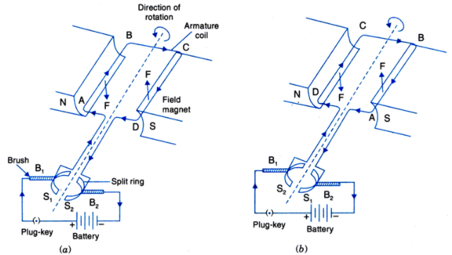
Starting me coil ko horizontal assume karte hai. Jab voltage supply dete hai toh current ABCD ke direction me flow hote hai ager hum coil ke AB side pe focus kare to ye ek current carrying conductor hoga jo magnetic field me placed hai isliye AB force experience karega. Hum force ki direction Fleming’s left hand rule se find kr sakte hai to aap dekh sakte hai ki AB ke liye force ki direction downward hai. Again hum CD ke liye left hand rule apply kare to force ki direction upwards hai. Ager hum BC ke side me force ki direction dekhe to is side ke liye force zero hoga jabki BC side se current flow ho raha hai fr bhi iske karan force zero hoga kyuki ye magnetic field ki direction ke along ya parallel hai. Isi tarah AD side ke liye bhi force zero hoga. AB aur CD ke liye equal and opposite force hai jo couple form karte hai jo motor me rotational motion k karan hai. Yaha pr coil anticlock wise direction me rotate karenge. Jab coil vertical position me pahuchega to ye commutator se contact loose kr dega kyuki commutator rings ke bich gap hai. Is time pe coil se current cutoff ho jayega but coil motion ke inertia ke karan continuously rotate hote rahega. Half rotation ke baad CD side left me aur AB side right me chala jayega. Is condition me commutator ka each half ring dusre carbon brushes ko touch karega. Ye coil me current ki direction ko reverse kr dega. Ab side CD me force ki direction downward ho jayegi aur AB side me force ki direction upward ho jayegi. In forces ke karan coil anticlockwise direction me continuously rotate karega. Iska mtlb hai ki half cycle ke baad current ki direction reverse ho jayegi aur continuously anticlock wise direction me rotate karega. Is tarah se electric motor work karega.
Ab hum dekhenge ki kin tariko se hum motor ki roation ki speed ko increase kr sakte hai. Motor ki speed ko badhane ke liye coil ki speed ko badhana padega jiske liye hume coil me lagne wale force ko badhana hoga.
F=BIl
Force badhane ke liye hum magnetic field ki strength badha sakte hai jiske liye hum soft iron core ko coil ke sath insert karke badha sakte hai.
Force ko increase karne ke liye hum current ki strength ko bhi increase kr sakte hai. Iske alawa hum coil ki length ko inrease karke bhi force ko increase kr sakte hai jiske hum coil ki area aur number turns ko increase kr sakte hai.
POINT 3
Principle of Electric Motor :
A motor works on the principle that when a rectangular coil is placed in a magnetic field and current passes through it, a force acts on the coil which rotates it continuously.
When the coil rotates, the shaft attached to it also rotates. In this way the electrical energy supplied to the motor is converted into the mechanical energy of rotation.
EXAMPLE 16
Name four appliances wherein an electric motor, a rotating device that converts electrical energy to mechanical energy, is used as an important component. In what respect motors are different from generators ?
The four appliances such as electric fans, washing machines, mixers grinders, electric drills, tape recorders, etc, uses an electric motor as a rotating device that converts electrical energy to mechanical energy. The motor is a machine which converts the3 electric energy into mechanical energy.
The generator is the device which converts mechanical energy into electrical energy. It is used to convert the mechanical power to electric power which varies in the magnitude with a specific frequency.
EXAMPLE 17
What is the role of the two conducting stationary brushes in a simple electric motor?
The two conducting stationary brushes draw from the battery and supply it to the armature of the motor because as the touch outer sides of the two halves of the split rings. The inner sides of split rings are insulated and attached to the axle of the motor.
EXAMPLE 18
Draw a labelled circuit diagram of a simple electric motor and explain its working. In what way theses simple electric motors are different from commercial motors?
The circuit diagram of a simple electric motor is shown below
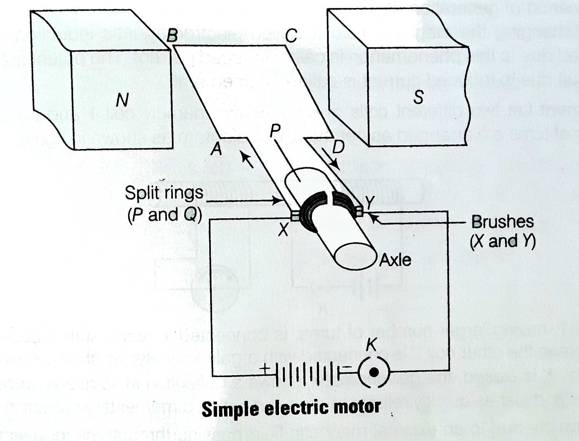
Working
(i) Let coil ABCD be in horizontal position. When the key is switched on, the current flows in direction DCBA and then leaves through the brushes B2 via ring R2
(ii) Applying Fleming's left -hand no force act on arm BC and AD as they are parallel to magnetic field, arm AB experiences a force in downward direction and arm CD experiences and equal force in upward direction. A torque on the coil and it rotates in an anti- clockwise direction.
(iii) while rotating, the coil reaches the vertical position, brushes loose contact with the rings and current stops flowing. But the coil does not stop due to inertia of motion.
(iv) When the coil passes the vertical position, the rings automatically change their positions and come in contact with opposite brushes.
(v) This reverses the direction of current through the coil but the direction of current on the right-hand side remains the same.
(vi) So, the force on right hand side is always upward and a force on left-hand side is always in downward direction. Thus, the coil continues to anti-clockwise direction.
A commercial electric motor is one which uses the following
(a) An electromagnet in place permanent magnet.
(ii) Large number of turns conducting wire in current carrying coil.
(iii) A soft iron core on which the coil is wound. The combination of soft iron core and coil is an armature. It enhances the power of motor.
Thus, commercial electric motors do not use permanent magnet to rotate the armature because permanent magnets are weak and do not produce strong magnetic field in the region.
ELECTROMAGNETIC INDUCTION
Jab bhi kisi magnetic field me rakhe coil ke magnetic field me change hota hai to us coil me current create ho jati hai ise hum induced current kahte hai. Yahi electromagnetic induction hai. The phenomenon in which electric current is generated by varying magnetic fields is appropriately called electromagnetic induction.
Electromagnetic induction ko hum Faraday ke ek experiment se samjhenge. Kisi paper ya wooden cylinder me insulated copper wire ko coil form karne ke liye lapetate hai jo solenoid ban jati hai. Is copper wire ke do ends ko galvanometer se connect karte hai aur ek magnet ko is coil ke paas place karte hai jaisa ki niche figure me dikhaya gaya hai. Is tym pe galvanometer ki reading zero hogi jab magnet stationary hoga. Jab hum magnet ke north pole ko solenoid ki taraf move karte hai to galvanometer right side me deflection deti hai.
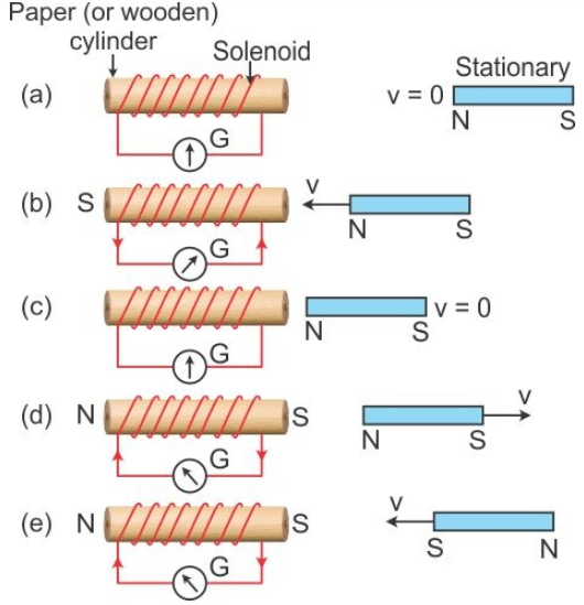
Jab magnet ke motion ko fr se stop kr dete hai to galvanometer ki reading fr se zero show karti hai. Ye proof hai ki jab tk magnet solenoid ke paas moving rahta hai tb tk solenoid me current flow hota hai jaise hi magnet ko move karna stop kr dete hai to solenoid me koi current flow nahi hota. Jab hum magnet ko solenoid se dur ki taraf move karte hai tab solenoid me current opposite direction me flow karta hai kyuki galvanometer left side me deflection show karta hai. Ager hum magnet ko jyada speed se move kare to deflection bhi jyada show karta hai. Ager hum magnet ke opposite pole means south pole ko solenoid ke paas leker aate hai to solenoid me current opposite direction me flow karta hai. Is situation me galvanometer the opposite direction me means left me deflection show karta hai. Faraday ne is experiment se ye observe kiya ki solenoid me current tabhi flow hota hai jab coil and magnet ke bich relative motion hota hai. Ager hum motion ka direction ko reverse kr dete hai to galvanometer me deflection ka direction bhi reverse ho jata hai. Solenoid me flow hone wala current aur galvanometer me show hone wala deflection ko hum increase kr sakte hai- by using strong magnet or by increasing motion of magnet. Ager hum solenoid me coils ke number of turns ko ya fr solenoide ki area ko bhi ager increase karde tab bhi solenoid me flow hone wale current ko hum increase kr sakte hai.
Faraday ke according ager coil aur magnet ke bich relative motion na ho to coil me magnetic flux constant rahega isliye galvanometer koi deflection show nahi karega. Jab magnet ko coil ki taraf ya opposite humne move kiya to coil me magnetic flux change hua jiske coil me emf induce hua. Ager circuit complete hai to isi induced emf ke karan circuit me current flow hota hai. Is experiment ke base pr hi Faraday ne two laws formulate kiya jo is prakar hai. Faraday's laws -
1. Whenever there is a change in the magnetic flux linked with a coil, an electromotive force (e.m.f.) is induced. Jab bhi coil se linked magnetic flux me change hota hai to emf induce hota hai.
2. Magnitude of induced emf directly proportional hota hai rate of change of magnetic flux ke jo coil se linked hota hai. Induced emf ka direction magnetic flux ke increase ya decrease hone pr depend karta hai.
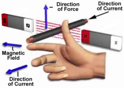
According to Fleming's right hand rule se forefinger center finger aur thumb ko ek dusre ke perpendicular stretch karte hai. Thumb conductor ke movement ke direction ko show karta karta hai, fore finger magnetic field ke direction ko show karta hai aur center finger induced current ke direction ko show karta hai.
Lenz’s law - lenz’s law states that the direction of the induced e.m.f. is such that it always tends to oppose the cause which produces it.
Lenz law, Newton's third law ko obey karta hai jiske according hr action ke liye equal and opposite reaction hota hai. Lenz’s law energy of conservation ko bhi follow karta hai jiske according energy na hi create ki ja sakti hai nahi destroy ki ja sakti hai isliye kisi bhi system me sare energies ka sum constant rahta hai. Ye lenz’s law Faraday's law of electromagnetic induction pr based hota hai.
POINT 4
Electromagnetic Induction :
Electromagnetic Induction is a current produced because of voltage production (electromotive force) due to a changing magnetic field.
Fleming's Right Hand Rule :
When we’ll stretch the thumb, central finger and forefinger of our right hand mutually perpendicular to each other, then the forefinger indicates the direction of magnetic field, the thumb indicates the direction of motion of conductor and the central finger indicates the direction of induced current.
EXAMPLE 19
Explain the meaning of the word 'electromagnetic' and 'induction' in the term electromagnetic induction. On what factors does the value of the induced current produced in a circuit depend? Name and state the rule used for determination of direction of induced current. State one practical application of this phenomenon in everyday life.
(i) Electromagnetic : relating to the inter-relation of electric currents(or fields) and magnetic fields.
Induction: production of effect elsewhere than at the original locus of activity without direct contact. In the magnetised (or electrified) object close to but not touching it.
(ii) The value of the induced current depends upon the rate of change of magnetic flux.
(iii) The direction of the induced current is determined by applying Fleming's Right Hand Rule.
(iv) An electric generator is a practical application of the phenomenon of electromagnetic induction.
EXAMPLE 20
A coil of insulated copper wire is connected to a galvanometer. What will happen if a bar magnet is :
(i) pushed into the coil ?
(ii) held stationary inside the coil ?
(iii) withdrawn from inside the coil ?
(i) As a bar magnet is pushed into the coil, a momentary deflection is observed in the galvanometer indicating the production of a momentary current in the coil.
(ii) When the bar magnet is held stationary inside the coil, there is no deflection in the galvanometer indicating that no current is produced in the soil.
(iii) When the bar magnet is withdrawn (or pulled out) from the coil, the deflection of the galvanometer is in the opposite direction showing the production of an opposite current.
EXAMPLE 21
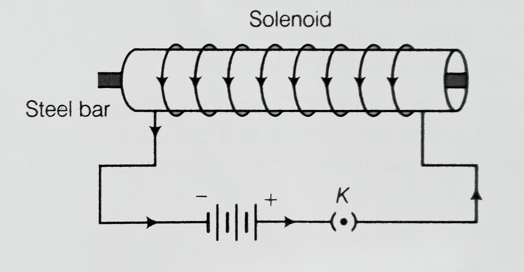
Under what conditions permanent electromagnet is obtained if a current carrying solenoid is used? Support your answer with the help of a labelled circuit diagram.
The conditions to obtain permanent electromagnet as following if a current carrying solenoid is used are
(i) The current through the solenoid should be direct current.
(ii) The rod inside is made of a magnetic material such as steel.
(iii) The magnetic material should be of high retentivity and should not lose it easily.
EXAMPLE 22
What does the direction of thumb indicate in the right-hand thumb rule? In what way this rule is different from Fleming's Left -hand rule.
According to Maxwell's right-hand thumb rule, the thumb shows the direction of electric current as shown in the figure. The curled finger holding the conductor give the direction of magnetic lines
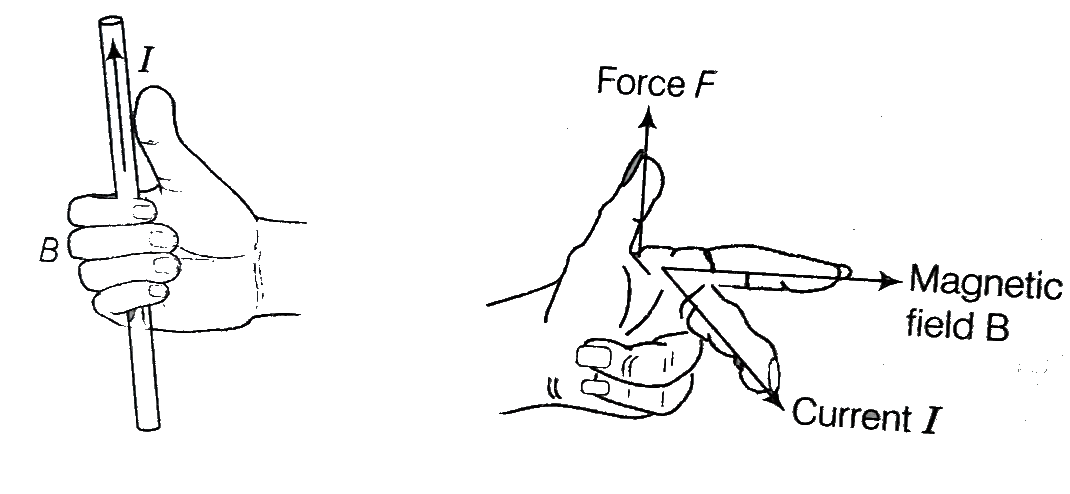
Whereas, Fleming's left-hand rule gives the direction of force experiences by a current carrying straight conductor placed in an magnetic field.
EXAMPLE 23
What does the divergence of magnetic field lines near the ends of a current carrying straight solenoid indicate ?
The divergence (degree of closeness) of magnetic field lines near the ends of a current carrying straight solenoid indicates a decrease in the magnetic field near the ends of the solenoid.
EXAMPLE 24
Explain the phenomenon of electromagnetic induction. Describe an experiment to show that a current is set up in a closed loop when an external to show that a current is set up in a closed loop when an external magnetic field passing through the loop increases or decreases.
This phenomenon was discovered by Michael Faraday and Joseph Henry in 1831. The phenomenon of generation of an electric current in a closed circuit from magnetic effects i.e., by changing the magnetic field is called electromagnetic induction. Electric current produced due to this phenomenon is called induced electromagnetic induction. Electric current produced due to this phenomenon is called induced current. The potential difference set in the circuit due to induced current is called induced emf.
Experiment Let two different coils of copper wire, namely coil 1 and coil 2, having large numbers of turns are arranged as per the circuit diagram as shown in figure.
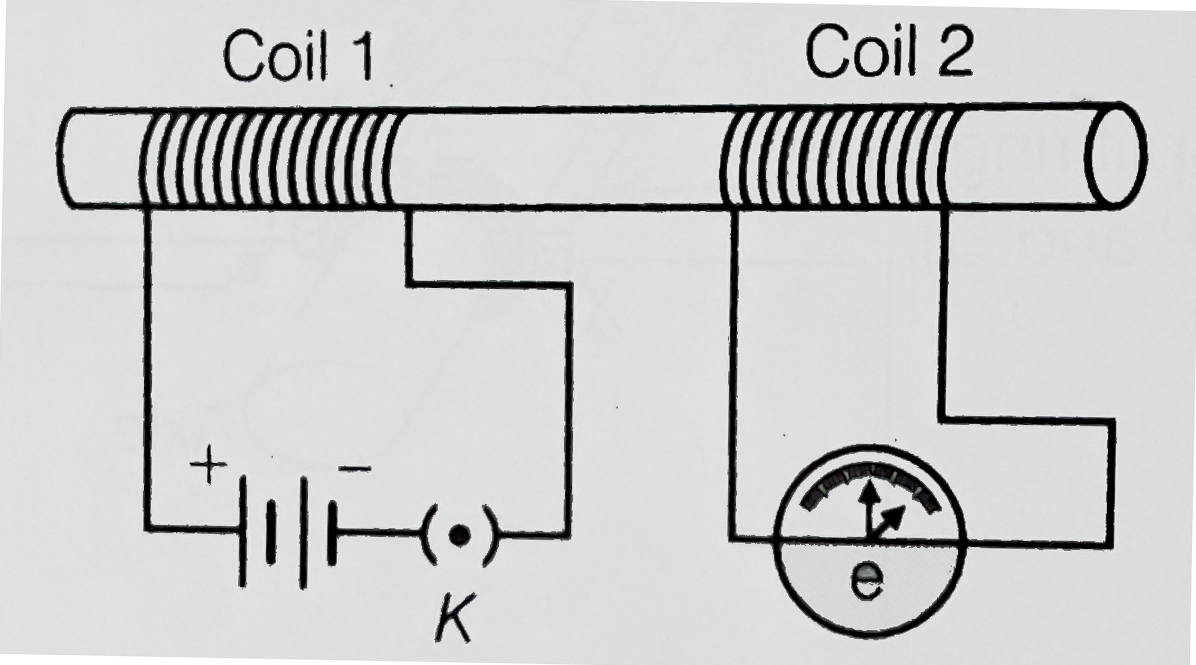
The coil 1, having a larger number of turns, is connected in series with a battery and a plug key whereas the other coil 2 is connected with a galvanometer as shown in circuit diagram. When key K is closed, the galvanometer shows a deflection in its needle instantly jumps to one side and just as quickly returns to zeron, indicating a momentary current in coil 2.
This happens due to an external magnetic field passing through the loop increases. When key K is open , the coil 1 is disconnected from the battery. The needle momentarily moves, but to the opposite side. It means that now the current flows in the opposite in coil 2. This happens due to an external magnetic field passing through the loop decreases.
ELECTRIC GENERATOR
Electric generator ek machine hota hai jo electric current ya electricity produce karta hai. Electric generator mechanical energy ko electrical energy me convert karta hai. Example, chhota generator jo bicycle me lighting ke liye use hota hai usse bicycle dynamo kehte hain. Electric generator electromagnetic induction ka ek application hai.
Inke ander turbine hota hai, jab turbine rotate hota hai tab electricity produce hota hai. Ye Electromagnetic Induction pr based hai jis ka aaviskar Michael Faraday ne 200 saal pehle kiya tha. Michael Faraday ne ye kaha tha ki ager hum ek conducting wire lenge aur use magnetic field me move krenge to uske ander electric current induce ho jata hai. Ager hum wire ko ek coil se replace kr denge aur coil ko turbine se attach kr denge aur jab turbine ko rotate karenge to ye coil magnetic field me move karne lagega aur iske ander electric current induce ho jaega.
Jab ek straight conductor ko magnetic field me move karte hain, to conductor me current induce hota hai. Electric generator me jab ek rectangular coil ko rapidly magnetic field me horseshoe-type magnet ke poles ke beech rotate karte hain, tab coil magnetic field lines ko cut karta hai jiske karan current coil me produce hota hai.
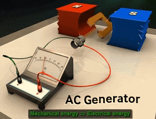
Iske help se hum apne ghar ke electrical appliances ka use kr sakte hain. Is puri device ko hum kahte hai electric generator. Ye spinning motion ya phir mechanical energy ko electrical energy me convert karta hai. Jab coil magnetic field me rotate karta hai to isme current kis direction me induce hota hai? Suppose turbine clockwise direction me rotate kr raha hai to coil bhi clockwise direction me rotate karega.
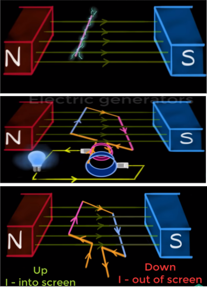
Induced current ka direction Flemming’s right-hand rule se pata kr sakte hain. Thumb, wire pr force ka direction batata hai, forefinger magnetic field ka direction aur middle finger induced current ka direction batata hai. Jab wire magnetic field me upr ke taraf jaega tab current inward direction me induce hota hai aur jab wire magnetic field me niche ke taraf jaega to induce current outward direction me hota hai. Jab bhi coil magnetic field ke perpendicular aata hai to current ka direction change ho jata hai.
Electric generator do type ke hote hain:
- 1. Alternating Current generator (A.C. generator),
2. Direct Current generator (or D.C. generator).
OMR (One Minute Revision)
- * Electric generator me conductor ko magnetic field me rotate karne ke liye mechanical energy ka use karte hai, electricity produce karne ke liye.
* Induced current highest hota hai jab coil ka direction of motion magnetic field ke right angle pr hota hai.
* Jab coil se linked magnetic flux maximum hota hai tab induced e.m.f zero ho jata hai.
A.C. GENERATOR
A.C. generator ka mtlb "Alternating Current generator" hai. A.C. generator ka use hum factory ya ghar pr karte hain jab mains se electric supply nahi hoti hai, as an alternative source of electricity. A.C. generator alternating current produce karta hai jo apna direction continuously reverse karta hai. A.C. generator ko alternator bhi kahte hain. The current which changes direction after equal intervals of time, is called an alternating current (abbreviated as AC). This device is called an AC generator.PRINCIPLE
A.C. generator mechanical energy ko electrical energy me convert karta hai.Generator me coil magnetic field me rotate karta hai. Is rotation ke karan magnetic flux jo coil se link hota hai vo change karta hai aur isliye e.m.f. (electromotive force) coil ke ends ke beech me induce hota hai. Generator load containing external circuit me source of current ke tarah act karta jab usse coil ke dono ends ke beech join karte hain.
CONSTRUCTION AND MAIN PARTS of A.C. GENERATOR
The main parts of an a.c. generator are:1. A horseshoe electromagnet NS,
2. The armature coil ABCD,
3. The slip rings S1, S2, and
4. The brushes B1, B2.
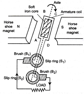
Horseshoe electromagnet NS: Ye strong magnet hai N aur S poles ka.
Armature coil ABCD: Soft iron core ka ka arms ABCD hai jisko armature coil kehte hai. Ye coil rapidly magnetic field me rotate hota hai poles of field magnet ke beech, by an axle fixed to it.
Slip rings S1 and S2: Do coaxial metallic rings S1 aur S2 hote hain jo coil ke along rotate hota hai. Ek end slip ring S1 se connected hota hai aur dusra end slip ring S2 se connected hota hai.
Dono ring stationary brush ke against slip karta hai.
Brushes B1 and B2: Do carbon brushes B1 aur B2 slip rings S1 aur S2 ke against gently press hote hain. Brushes ke dusre end generator ke terminal ke tarah act karte hain jiske across load containing external circuit connected hote hain. Brushes B1 aur B2 coil aur slip rings ke along slip nahi karte hain.
WORKING OF A.C. GENERATOR
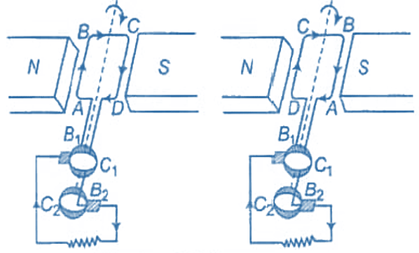
Jab armature poles of field magnet ke beech rotate karta hai to armature se linked magnetic flux continuously change karta hai. Is karan armature me e.m.f. (electromotive force) induce hota hai jiske karan electric current produce hota hai.Jab armature clockwise direction me rotate karta hai, tab Flemming’s right hand rule ko apply karke, external circuit me induced current ko find kr sakte hain. Induced current opposite direction me flow hota hai jiske karan galvanometer me deflection ka direction left me hota hai.
Thus, we see that the direction of induced current changes in the external circuit after every half revolution of the armature, i.e., after the armature has turned through an angle of 180° from its initial position. Hence, the induced current is alternating in nature.
Generator me induced e.m.f. (electromotive force) ka magnitude increase ho sakta hai;
(i) Armature ke number of turns ko increase karke
(ii) Armature ke area ko increase karke
(iii) Armature ke speed of rotation ko increase karke aur
(iv) Magnetic field ke strength ko increase karke.
OMR (One Minute Revision)
- * A.C. generator Electromagnetic Induction ke principle pr work karta hai.
- Hamare gharon me AC electric power 220 V ka receive hota hai aur frequency 50 Hz hota hai.
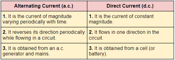
DISTINCTION BETWEEN A.C. AND D.C.
DIRECT CURRENT (DC) GENERATOR
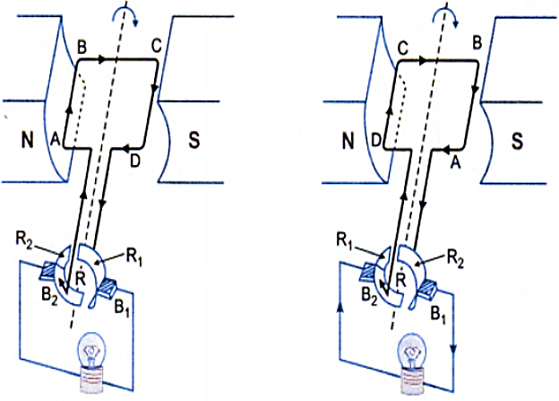
D.C. generator ka principle, construction aur working A.C. generator se same hai (except in the place of slip-rings as sliding contacts, it has a split-ring or a commutator). Split ring me R1 aur R2 same ring ke do halves hote hain. Armature coil ka ends in rings se connected hota hai aur ye rings armature me rotate karte hain. Split-ring ko use karke, external circuit me induced current ka direction change nahi hota hai (armature ke complete rotation ke throughout).The current in the external circuit always flows in the same direction. Hence the induced current is unidirectional, i.e., direct current (DC).
Advantages of AC over DC:
1. AC kisi bhi desired voltage pr obtain kar sakte hain, transformer ke help se.2. AC transmission me power wastage almost negligible hota hai aur isliye transmission ka cost bhi low hota hai.
3. AC ko choke coil use karke control kiya ja sakta hai aur energy loss kam hota hai jabki DC sirf ohmic resistances use karke control kiya ja sakta hai jo bahut jyada energy loss involve karta hai, heat ke form me.
4. Jab jarurat ho, AC ko DC me change kiya ja sakta hai.
5. AC machines bahut stout aur durable hote hain aur unme jyada maintenance ki jarurat nahi hoti.
Disadvantages of AC over DC
1. AC DC se zyada dangerous hai kyun ki AC kisi person ko apne taraf attract karta hai jabki DC repel karta hai. AC DC ke comparison me serious shock deta hai.2. AC electroplating, electrotyping aur dusre electrolytic processes ke liye use nahi kiya ja sakta. In cases me DC use hota hai.
DISTINCTION BETWEEN AN A.C. GENERATOR AND D.C. MOTOR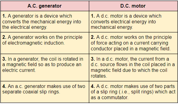
POINT 5
Principle of Electric Generator :
It is based on the principle of electromagnetic induction. It states that “an induced current is produced in a coil placed in a region where the magnetic field changes with time.” The direction of induced current is given by Fleming’s right-hand rule. An electric generator converts mechanical energy into electrical energy.
Alternating Current :
The current which changes direction after equal intervals of time, is called an alternating current (abbreviated as AC). This device is called an AC generator.
Direct Current :
The current in the external circuit always flows in the same direction. Hence the induced current is unidirectional, i.e., direct current (DC).
EXAMPLE 25
What is the difference between a direct current and an alternating current? How many times does AC used in India change direction in one second?
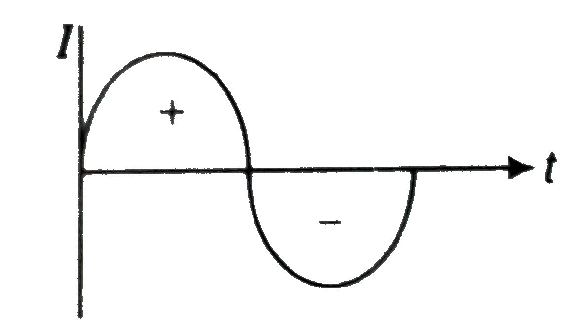
The basic difference between direct current and an alternating current is as follows Alternating Current is an electric changes its direction (i.e., polarity after a certain fixed interval of time. Graphically it can be represented as following
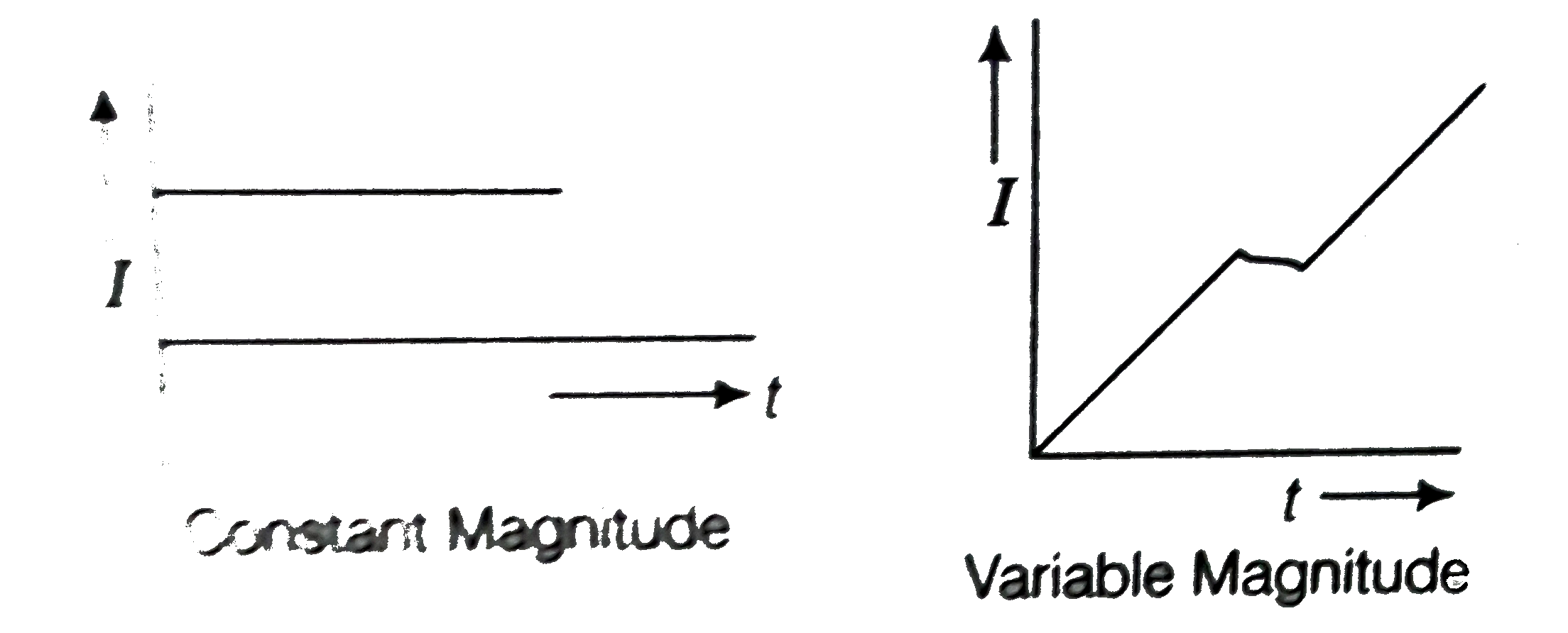
Direct Current is an electric current is either constant or variable, but the direction of flow in a conductor remains the same. Sources of DC are voltaic cell, a dry cell, battery, DC generator etc and graphically it is shown as
The frequency of AC in India is 50 cycle/s
∴ Time period of AC is , Tf=150s
but AC changes its directions after every half every time period. T=150×2=1100s
Thus, in India AC change its direction after every 1100s
So, in one second AC changed its direction 100 times.
EXAMPLE 26
Describe the working of an AC generator with the help of a laballed circuit diagram. What changes must be made in the arrangement to convert into a DC generator?
The working of an AC generator is as follows
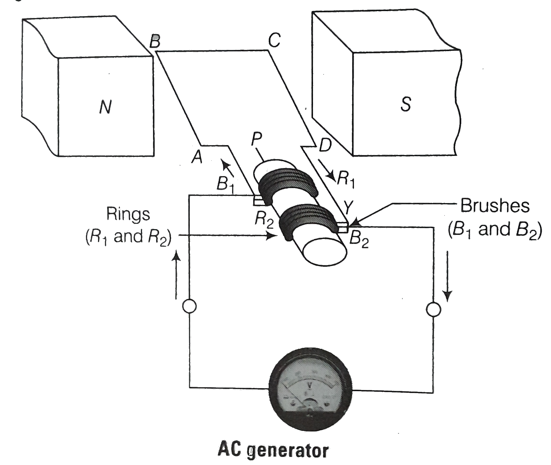
As the coil rotates, the two rings also rotate with the coil. The brushes P and Q keep contact with the rotating ring. When the coil starts rotating with arm AB moving up and CD moving down (clockwise ) cutting the magnetic lines. According to Fleming's right-hand rule, the current is induced in these arms in the direction ABCD.
After half rotation, arm CD moves down and AB moves up. As a result, direction of current in each segment changes, giving rise to net induced current in the direction DCBA. Thus, after every rotation, polarity of current in the respective arm changes , thereby generating direct current.
To convert an AC generator into a DC generator, a split ring commutator is used. This helps in producing direct current.
DOMESTIC ELECTRIC CIRCUITS
1. Electric Cable or Overhead Wires: Kisi ghar me electric power overhead wires ya underground cables ke through supply hota hai.
Cable ka 3 separate insulated wires hote hain:
- (a) live wire (or phase or positive)
(b) neutral wire (or negative)
(c) earth wire.
2. Pole Fuse: Electric lines ke gharon me ghusne se pehle, agency jo electricity supply karta hai vo livewire me fuse place karta hai. Is fuse ko Pole Fuse ya Company Fuse kehte hain. Is fuse ka current rating load sanctioned pr depend karta hai jo agency gharon ko deti hai.
3. Energy Metre or kWh metre: Cable jo energy metre se connected hota hai vo ghar ka electricity consumption kilowatt hour (kWh) me record karta hai.
4. Main Fuse: The live wire coming out from the output terminals of the kWh meter has another fuse in it which is called the main fuse.
5. Main Switch: Live aur neutral wires main switch se connected hota hai. Ye double pole switch hota hai jiska iron covering hota hai. Main switch ka covering bhi locally earthed hota hai. Switch live aur neutral wire ko cut kar sakta hai household circuit se, single lever ko operate karke.
6. Distribution Board: Main switch se jo power lines aate hain unhe distribution board me le jaya jata hai.
7. House-Wiring: Wiring ke do system ho jisse ghar me power distribute hota hai.
-
(a) The Tree System
(b) The Ring System
(a) The Tree System: In the tree system of wiring, different branch lines are taken out from the distribution board to different parts of the house in almost the same way as the branches from the trunk of a tree. Distribution board ke fuses ke through wires ghar ke different parts me le jaya jata hai (in almost the same way as the branches from the trunk of a tree). Hr ek branch line ko live wire me fuse ke through room tak le jaya jata hai. Hr ek separate circuit me different appliances across live aur neutral wire connected hote hai. Hr appliance ka flow of current ko ON/OFF karne ka separate switch hota hai. Hr appliance ka equal potential difference hota hai isliye vo ek dusre se parallel connected hote hain. Electric fuses sare domestic circuit ka important component hota hai. Circuit me fuse appliances aur circuits ke damage ko prevent karta hai.
Fuse me Joule heating ke karan fuse melt ho jata hai aur electric circuit ko break kar deta hai. Overloading bahut sare appliances ko ek single socket se connect karne se ho sakta hai.
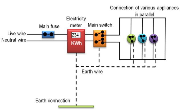
Features of Tree System of Wiring:
(i) Different circuits are connected in parallel so that if there is a short-circuiting in one distribution circuit, its fuse will blow off without affecting the supply in the other circuits.(ii) Neutral wire (N) aur earth wire (E) sare circuits me common hote hain.
(iii) Ek room ke sare appliances parallel me connected hote hain taki ve same voltage me work kar sake.
(iv) Live wire (L) ke connections ko appliance ke ek terminal pr le jaya jata hai switch (S) ke through. Dusra terminal neutral wire (N) se connected hota hai circuit ko complete karne ke liye.
Disadvantages of Tree System of Wiring:
(i) Since all circuits originate from the main distribution board, longer length of the wire is required for wiring various rooms and other places in the house.(ii) When a fuse in one particular line blows off, all the appliances in that line are disconnected.
(iii) Plugs and sockets of different current capacities are required for different appliances depending upon the wattage.
(iv) On account of the large length of wire, it is an expensive wiring system.
(v) It takes a long time to be installed.
Ring System me ye sare disadvantages remove ho jate hain.
EARTHING OF ELECTRICAL APPLIANCES
Earthing of an electrical appliance means connecting the metallic body of the powered appliance to the earth through the earth wire. Ye ek safety measure hai jo appliance ke metallic body me leakage of current ensure karta hai. Metallic body ke potential ko earth (zero volt) se equal rakha jata hai aur user ko severe electric shock nahi milta hai (by means of a metal wire called “earth wire”)SHORT CIRCUIT
Ager kisi defective ya damaged wiring ke karan, live aur neutral wire direct contact me aa jate hain to circuit ka resistance almost zero ho jata hai aur circuit me extremely large current flow hota hai. Isse short circuiting kehte hain.Live wire me electric fuse ka use karke appliances ko short circuiting se protect kar sakte hain.
OVERLOADING
Mains se nikalne wala current jab safety limit exceed kar jata hai, tab usse overloading kehte hain.Electric fuse ka use karke circuit ko overloading se protect kiya ja sakta hai.
ELECTRIC FUSE
Electric fuse ek safety device hai jo electric circuit ko overloading aur short circuiting se protect karta hai. Fuse wire ek piece of wire hota hai is jiska material low melting point ka hota hai aur vo circuit me live wire se connected hota hai. Fuse wire electric circuits me series me connected hota hai. Jab excessive current flow hota hai tab fuse melt ho jata hai aur circuit break ho jata hai.Fuse wire pure tin ya tin-copper alloy se banta hai, jiska melting point low hota hai aur jab current safe value se exceed hota hai to ye melt ho jata hai aur circuit break kr deta hai. Fuse wire ka proper thickness hona chahiye jo wire ke maximum current pr depend karta hai.
POINT 6
Electric Fuse : It is a safety device to limit the current in an electric circuit.
EXAMPLE 27
Why is Series Arrangement not used for Domestic Circuits ?
In domestic circuits, series arrangement is not used because of the following reasons :
1. The total potential difference available (usually 220 volts) is divided between various appliances in the circuit according to their resistances since the current flowing through all the appliances is the same. Thus, each appliance will not get the required potential difference for it to operate properly.
2. If one of the appliances is out of order, e.g., if a bulb gets fused, all the appliances in the circuit will stop working as the circuit gets broken.
3. All the appliances will work simultaneously whether we want them to work or not, thereby involving a lot of power wastage.
4. If we switch off any one of the appliances, the circuit is broken and all the appliances will stop working.
EXAMPLE 28
What are the two main systems of wiring commonly used in household circuits? Which of the two is better and why?
(a) Tree system (b) Ring system.
Ring system of wiring is better than the tree system due to the following reasons:
(a) Every appliance has its own fuse and as such in case of short-circuiting, only that particular appliance is disconnected from the circuit without affecting other appliances.
(b) Since the length of wire is considerably small as a single ring feeds the entire house, the cost of wire is reduced.
(d) It is easier to install and maintain.
EXAMPLE 29
An electric oven of f2 kW power rating is operated in a domestic electric circuit (220 V) that has a current rating of 5 A. What result do you expect ? Explain.
We will first calculate the current drawn by this electric oven.
Now, Power, P = 2 kW
=2×1000 W
= 2000 W
Potential difference or Voltage, V = 220 V
And, Current drawn, I = ? (To be calculated)
Now, Power, P=V+I
So, 2000=220×I
And Current drawn, I=2000220
= 9 A
Now, the current drawn by this electric oven is 9 amperes which is very high but the fuse in this circuit is only of 5 ampere capacity. So, when a very high current of 9 A flows through the 5 A fuse, the fuse wire will get heated too much, melt and break the circuit, cutting off the power supply. Thus, when a 2 kW power rating electric oven is operated in a circuit having 5 A fuse, the fuse will blow off cutting off the power supply in this circuit.
EXAMPLE 30
A circuit has a fuse of 5 A. What is the maximum number of 100 W (220 V) bulbs that can be safely used in the circuit ?
Suppose x bulbs can be used safely.
Now, Power of 1 bulb = 100 W
So, Power of x bulbs, P = 100 × x watts
Potential difference, V = 220 volts
Current, I = 5 amperes
Now, Power, P=V×I
So, 100×x=220×5
x=220×5100
x=11
Thus, a maximum number of 11 bulbs can be used.
EXAMPLE 31
What precautions should be taken to avoid overloading of domestic electric circuits ?
(i) Too many high power rating electrical appliances (such as electric iron, geyser, air conditioner, etc.) should not be switched on at the same time.
(ii) Too many electrical appliances should not be operated on a single socket.
EXAMPLE 32
Name two safety measures commonly used in domestic electric circuits and appliances.
(i) Provision of electric fuse.
(ii) Earthing of metal bodies of electrical appliances.
EXAMPLE 33
What is the role of fuse, used in series with any electrical appliance? Why should a fuse with defined rating not be replaced by one with a larger rating?
The main role used in series with any electrical appliance limits the current through the appliance. It protects the appliance due to short-circuiting or over/ loading as when current exceeds the limit for which the fuse is rated, it blows off and the appliance is disconnected from the electric supply.
When a fuse with defined rating for a particular is replaced by one with larger rating, it does not blow off and the appliance is damaged due to larger current passing through it.
EXAMPLE 34
Draw an appropriate schematic diagram showing common domestic circuits and discuss the importance of fuse. Why is it that a burnt out fuse should be replaced by another fuse of identical rating ?
The schematic diagram of common domestic circuit is shown below
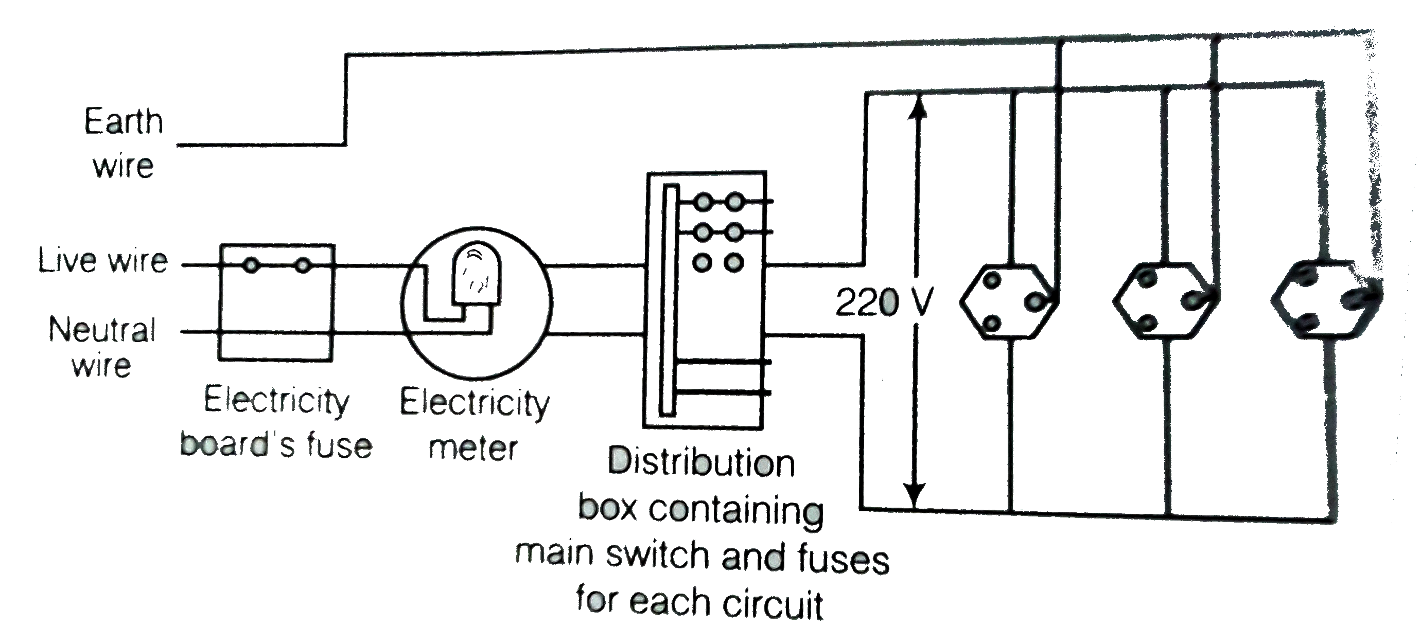
Fuse is a safety device having short length of thic wire made of thin (25%) and lead (75%) alloy having low melting point around 200∘C. It is an important component of all domestic circuits. A fuse in a circuit prevents damage to the appliances and the circuit due to overloading and short-circuiting. The use of an electric fuse prevents the electric and the appliance from a possible damage by stopping the flow of unduly high electric current. The fuse is placed in series with the device.
A fuse wire works because of its lower melting point which is possible. If a fuse with larger rating is used with an appliance, the fuse wire shall not melt and hence would fall to serve the required purpose. Due to this, a fuse with defined rating should not be replaced by one with a larger rating.
SUMMARY
1. A compass needle is a small magnet. Its one end, which points towards north, is called a north pole, and the other end, which points towards south, is called a south pole.
2. A magnetic field exists in the region surrounding a magnet, in which the force of the magnet can be detected.
3. Field lines are used to represent a magnetic field. A field line is the path along which a hypothetical free north pole would tend to move. The direction of the magnetic field at a point is given by the direction that a north pole placed at that point would take. Field lines are shown closer together where the magnetic field is greater.
4. A metallic wire carrying an electric current has associated with it a magnetic field. The field lines about the wire consist of a series of concentric circles whose direction is given by the right-hand rule.
5. The pattern of the magnetic field around a conductor due to an electric current flowing through it depends on the shape of the conductor. The magnetic field of a solenoid carrying a current is similar to that of a bar magnet.
6. An electromagnet consists of a core of soft iron wrapped around with a coil of insulated copper wire.
7. A current-carrying conductor when placed in a magnetic field experiences a force. If the direction of the field and that of the current are mutually perpendicular to each other, then the force acting on the conductor will be perpendicular to both and will be given by Fleming’s left-hand rule. This is the basis of an electric motor. An electric motor is a device that converts electrical energy into mechanical energy.
8. The phenomenon of electromagnetic induction is the production of induced current in a coil placed in a region where the magnetic field changes with time. The magnetic field may change due to a relative motion between the coil and a magnet placed near to the coil. If the coil is placed near to a current-carrying conductor, the magnetic field may change either due to a change in the current through the conductor or due to the relative motion between the coil and conductor. The direction of the induced current is given by Fleming's right-hand rule.
9. A generator converts mechanical energy into electrical energy. It works on the basis of electromagnetic induction.