Complete Solutions to Illustration of chapter ELECTROMAGNETIC INDUCTION AND ALTERNATING CURRENT of Class 12 book with complete answers and questions
| Class 12 | PHYSICS |
| Chapter | ELECTROMAGNETIC INDUCTION AND ALTERNATING CURRENT |
| PHYSICS GALAXY | Illustration |
| Number Of Questions | 25 |
| Academic Year | 2023-24 |
There are two stationary loops with mutual inductance `L_(12)`. The current is one of the loops starts to be varied as `I_(1) = alpha t` where `alpha` is a current, `t` is time. Find the time dependence `I_(2) (t)` of the current in the other loop whose inductance is `L_(2)` and resistance `R`.
03:10View SolutionA capacitor of capacitance `25muF` is charged to `300V`. It is then connected across a `10mH` inductor. The resistance in the circuit is negligible.
a. Find the frequency of oscillation of the circuit.
b. Find the potential difference across capacitor and magnitude of circuit current `1.2ms` after the inductor and capacitor are connected.
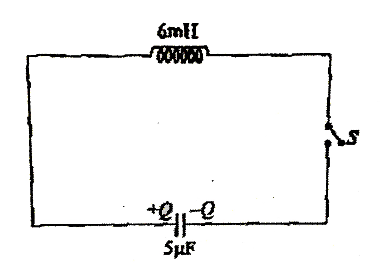
c. Find the magnetic energy and electric energy at `t=0` and `t=1.2ms`.07:12View SolutionIn circuit shown in figure charge on capacitor is `Q = 100muC`. If switch is closed at t=0 find current in circuit when charge on capacitor reduces to `50muC`. Also find the maximum current in circuit.
 03:21View Solution
In an `L-C` circuit, `L=3.3H` and `C=840pF`. At `t=0` charge on the capacitor is `105muC` and maximum. Compute the following quantities at `t=2.0ms`.
a. The energy stored in the capacitor.
b. The total energy in the circuit,
c. The energy stored in the inductor.02:43View SolutionIn an oscillating `L-C` circuit in which `C = 4.00muF`, the maximum potential difference capacitor during the oscillations is `1.50 V` and the maximum current through `50.0 mA`.
(a) What is the inductance `L`?
(b) What is the frequency of the oscillations?
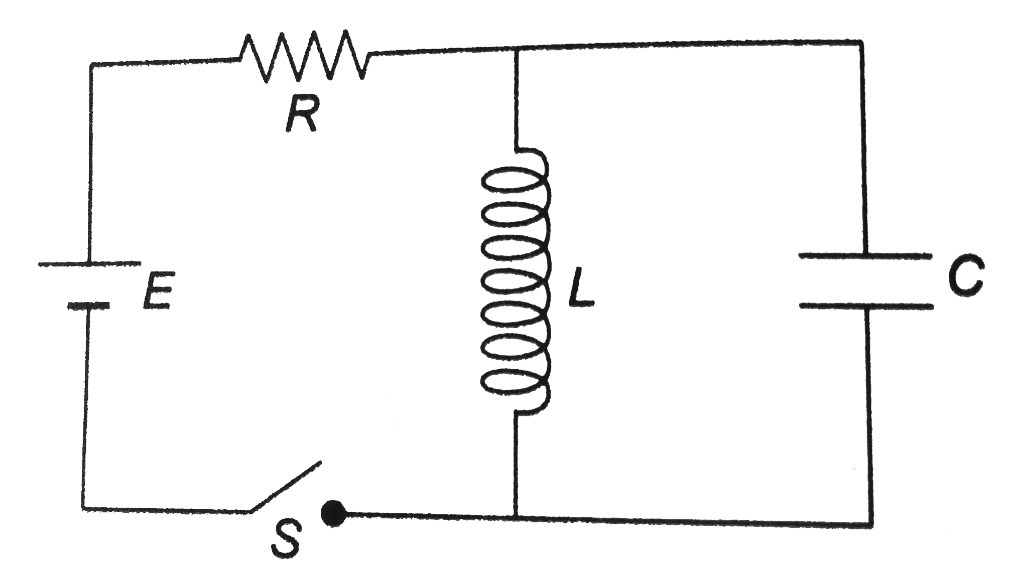
(c) How much time does the charge on the capacitor take to rise from zero to its maximum value?02:57View SolutionIn the circuit shown in the figure, `E = 50.0 V, R = 250 Omega` and `C = 0.500 muF.` The switch `S` is closed for a long time, and no voltage is measured across the capacitor. After the switch is opened, the voltage across the capacitor reaches a maximum value of `150 V`. What is the inductance `L`?
 01:49View Solution
An inductor of inductance `2.0mH` is connected across a charged capacitor of capacitance `5.0muF` and the resulting `L-C` circuit is set oscillating at its natural frequency. Let `Q` denote the instantaneous change on the capacitor and `i` the current in the circuit. It is found that the maximum value of `Q` is `200muC` .
(a) When `Q=100muC` , what is the value of `|di//dt|` ?
(b) When `Q=200muC` , what is the value of `i` ?
(c)Find the maximum value of `i`
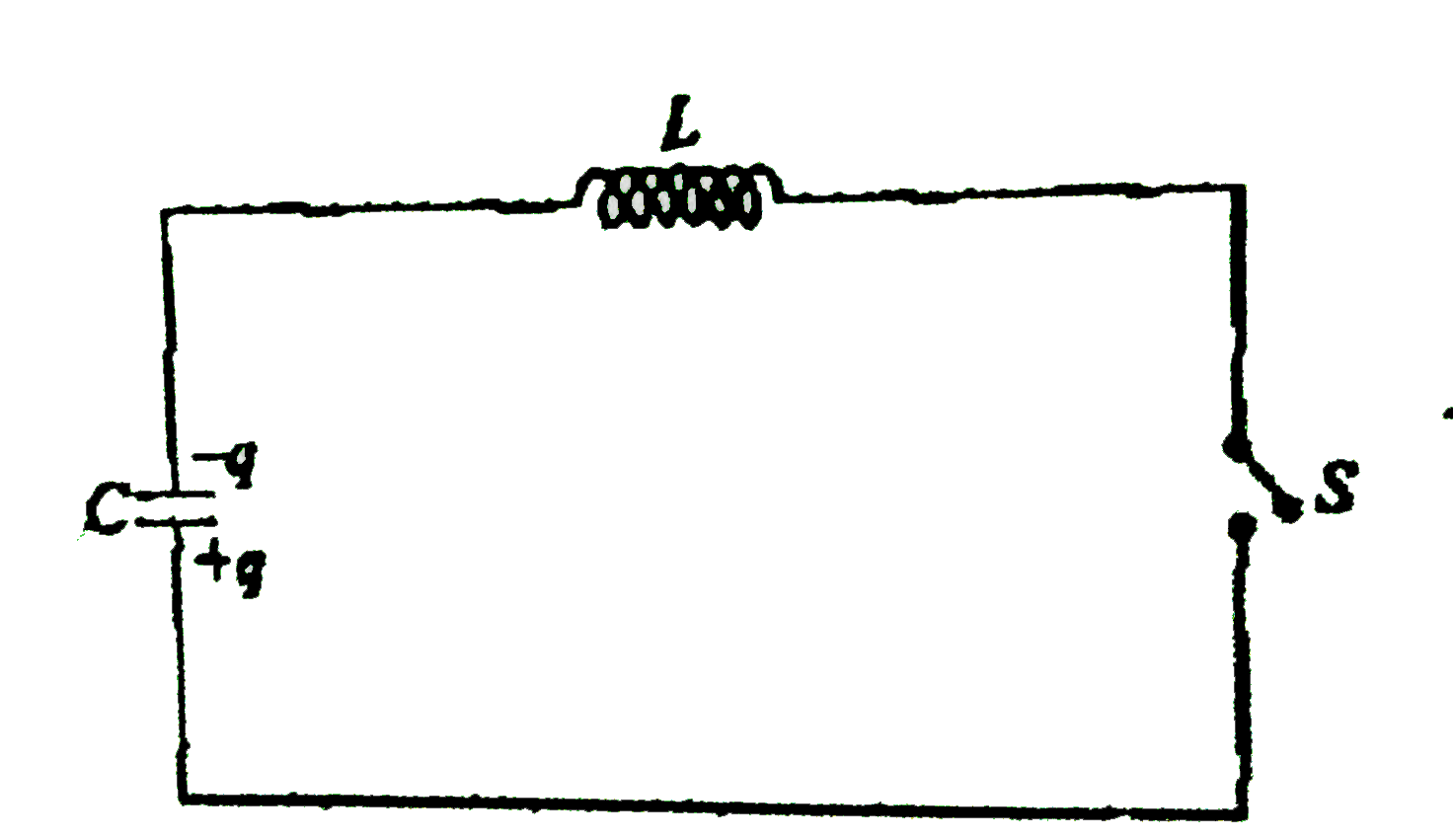
(d) When `i` is equal to one-half its maximum value, what is the value of `|Q|` ?12:04View SolutionIn figure-5.143 ifS is closed at t=0, find charge on capacitor as a function of time. Time inductor is active with initial current `I_(0)` in it.
 03:23View Solution
A bar magnet haxs its pole strength 4.5 Am and length 12 cm. the cross sectional area of the magnet is `0.9 cm^(2)`. Find the total dipole moment of the magnet and intensity of magnetsiation of the magnetic material.
02:50View SolutionFor a magnetising field of intensity `2xx10^3A//m`, aluminium at `280K` acquires intensity of magnetisation of `4*8xx10^-2Am^-1`. Find the susceptibility of aluminium at `280K`. If the temperature of the metal is raised to `320K`, what will be its susceptibility and intensity of magnetisation?
03:01View SolutionA piece of iron of mass 8.4 kg is repeatedly magnetised and demagnetised by an external periodic time varying magnetic field of frequency 50Hz. In the iron piece it is measured that rate of heat dissipation is `6.4xx10^(4)J//hr`. If iron density is `7200Kg//m^(3)` find the energy dissipated in iron piece per cycle per unit volume of it.
03:31View SolutionAn electric bulb is designed to operate at `12` volts `DC`. If this bulb is connected to an AC source and gives normal brightness, what would be the peak voltage of the source?
04:24View SolutionThe current in a discharging `LR` circuit is given by `I = i_0 e^(-t/tau)` where `tau` is the time constant of the circuit. Calculate the rms current for the period `t = 0` to `t = tau`.
04:53View SolutionA direct current of 2A and an AC of peak value 2A flows through resistances `2Omega` and `1Omega` respectively. Find the ratio of heat produced in the two resistances in same interval.
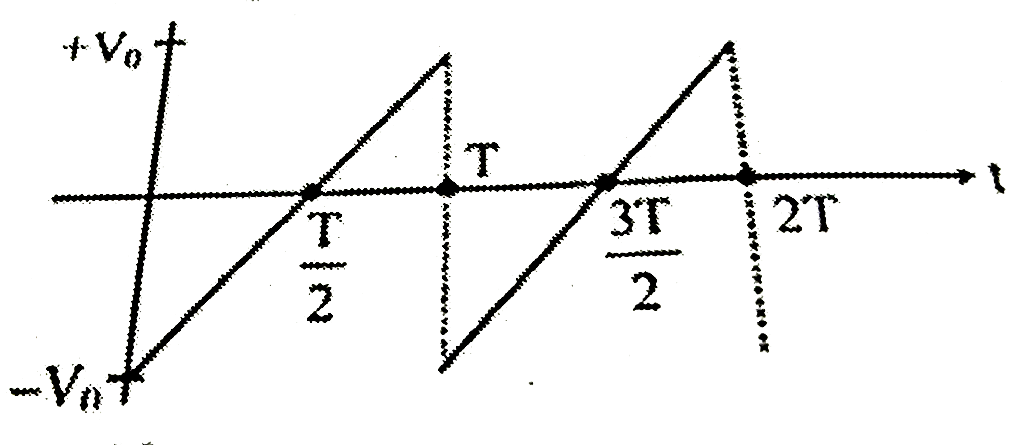
02:36View SolutionRms value of the saw-tooth voltage of peak value `V_(0)` as shown in-
 07:48View Solution
A `10 mu F` capacitor in series with a `40 Omega` resistance is connected to a 110 V, 60Hz supply. (a) What is the maximum current in the circuit ? (b) What is the time lag between current maximum and voltage maximum ?
04:48View SolutionAn electric lamp which runs at 40V and consumes 10A current is connected to AC mains at 100V, 50Hz supply. Calculate the inductance of the required choke for lamp to glow at full brightness.
04:23View SolutionIn the figure shown `i=10e^(-4t)`A. Find `V_L` and `V_(ab)`
 01:28View Solution
In the figure shown, `i_(1)=10e^(2t)A` , `i_(2)=4A` and `V_(c)=3e^(-2t)V` Determine
(a) `i_(L)` and `V_(L)`
(b) `V_(ac)` , `V_(ab)` and `V_(cd)`
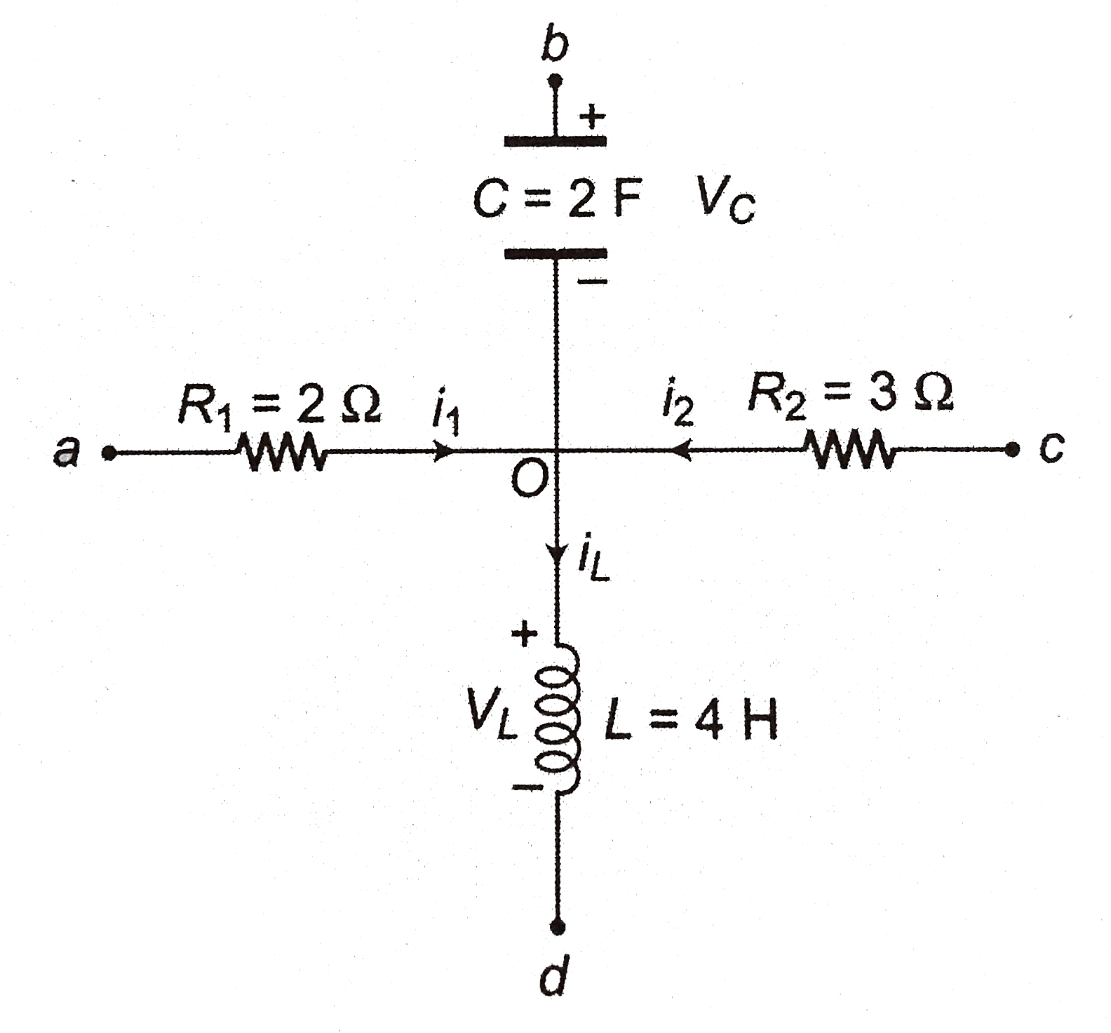 08:43View Solution
When 100 DC is applied across a solenoid, a steady current of 1A flows in it. When 100V AC is applied across the same solenoid, current drops to 0.5A. If the frequency of AC source is `(50sqrt(3))/(pi)` Hz, find the resistance and inductance of the solenoid.
04:13View SolutionIn a circuit a resistance of `40Omega` and capacitor of capacitance `(1250)/(9pi)muF` are connected in series across a 500V, 120Hz AC source Find the effective current in circuit and phase difference between current and source EMF.
05:27View SolutionA `12Omega` resitance and an inductance of 0.05/ `piH` with negligible resistance are connected in series. Across the end of this circuit is connected a 130 V alternating voltage of frequency 50Hz. Calculate the alternating current in the circuit and potential difference across the resistance and that across the inductance.
02:35View SolutionAn `AC` source of angular frequency `omega` is fed across a resistor `R` and a capacitor `C` in series. The current registered is `I`. If now the frequency of source is changed to `omega//3` (but maintaining the same voltage), the current in the circuit is found to be halved. The ratio of reactance to resistance at the original frequency `omega` will be.
05:46View SolutionIn a series RL circuit with `L=(175)/(11)mH` and `R=12Omega` and AC source of emf `e=130sqrt(2)V`, 50Hz is applied. Find the circuit impedance and phase difference of EMF and current in circuit.
03:19View SolutionA `200km` long telegraph wire has capacitance of `0.014 mu F//km` If it carries an alternating current of `50 xx 10^(3)` Hz what should be the value of an inductance required to be connected in series in series so that impedance isw minimum .
03:36View Solution
Illustration questions and complete solutions for chapter ELECTROMAGNETIC INDUCTION AND ALTERNATING CURRENT of GK PUBLICATIONS PHYSICS (HINGLISH) of Class 12
