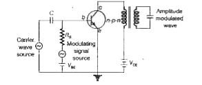
Draw a circuit diagram for an amplitude modulator and explain the production of amplitude modulated carrier wave.
Circuit diagram for an amplitude modulator as shown below.

The basic circuit of an amplitude modulator is shown in the figure. It is essentially a common emitter amplifier for the carrier wave signal. The base biasing voltage, in this case, is the sum of DC and the modulating signal. As the base biasing voltage changes, amplification changes.
Therefore, output voltage will be a carrier wave varying in amplitude in accordance with the biasing modulating voltage. This is the amplitude modulated wave.
Similar Questions
Knowledge Check
- Question 1 - Select One
In amplitude modulation, carrier wave frequencies are:
Alower compared to those in frequency modulation.Bhigher compared to those in frequency modulation.Csame as in frequency modulation.Dlower sometimes and higher sometimes to those in frequency modulation - Question 2 - Select One
Both amplitude modulation (AM) and frequency modulation (FM) are used for radio broadcasting. The amplitude of the high frequency carrier wave is varied or modulated in accordance with the variations in the amplitude of the audio signals that are to be transmitted, in te process of amplitude modulation in frequency modulation te amplitude of the carrier remains constant but its frequency is varied inn accordance withh the audio signal. Reception with AM signals is in general is affected by interference of various kinds ad elaborated equipment is required for FM broadcast.
A radio frequency carrier wave can be modulated using a-AdiodeBtriodeCdiode or a triodeDnone of the above
Explain amplitude modulation. Derive the voltage equation of an amplitude modulated wave.
View SolutionDraw a block diagram of a simple amplitude modulation. Explain briefly how amplitude modulation is achieved.
View SolutionWhy is the amplitude of modulating signal kept less than the amplitude of carrier wave ?
View Solution(a) What is amplitude modulation? Draw a diagram showing an amplitude modulated wave obtained by modulation of a carrier sinusoidal wave on a modulating signal.
(b) Define the terms (i) modulation index, and (ii) side bands. Mention the significance of side bands.View SolutionIn amplitude modulation, carrier wave frequencies are:
View SolutionWrite two basic modes of communication. Explain the process of amplitude modulation. Draw a schematic sketch showing how amplitude modulated signal is obtained by superposing modulating signal over a sinusoidal carrier wave.
View Solution
