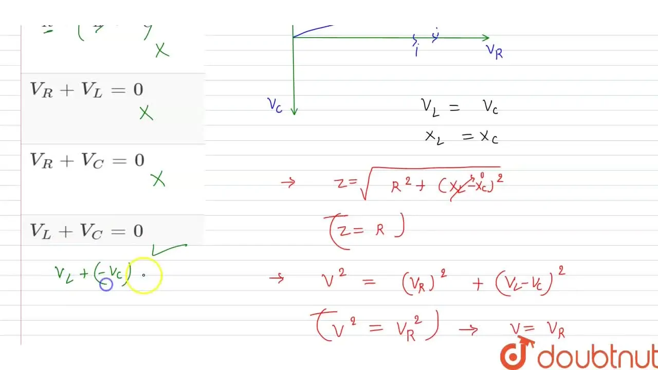
At resonance in series R-L-C circuit _PHY_E06_308_Q01.png)
VR+VL+VC=0
VR+VL=0
VR+VC=0
VL+VC=0
Step by step video & image solution for At resonance in series R-L-C circuit by Physics experts to help you in doubts & scoring excellent marks in Class 12 exams.
Similar Questions
The value of current at resonance in a series L-C-R circuit is affected by the value of
View SolutionIllustrate the phenomena of resonance in series LCR A/C circuit with illustration.
View SolutionAssertion : At resonance, LCR series circuit have a minimum current.
Reason : At resonance, in LCR series circuit, the current and e.m.f. are not in phase with each other.View SolutionAt resonance frequency the impedance in series LCR circuit is
View SolutionIf V0 and I0 are the peak current and voltge across the resistor in a series L−C−R circuit, then the power dissipated in the circuit is (powerfac→r=cosθ)
View SolutionAt resonant frequency the current amplitude in series LCR circuit is
View SolutionAssertion: In series, L-C-R voltage across capacitor is always less than the applied voltage.
Reason: In series L-C-R circuit, V=√(V2R+(V2L−V2C))View SolutionAssertion : In series L−C−R,AC circuit, current and voltage are in same phase at resonance.
Reason : In series L−C−R,AC circuit, resonant frequency does not depend on the value of resistance. Hence, current at resonance does not depend on resistance.View SolutionPower factor in a series R-L-C resonant circuit is
View SolutionIn L−C−R series circuit
View Solution


