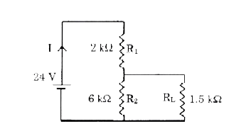
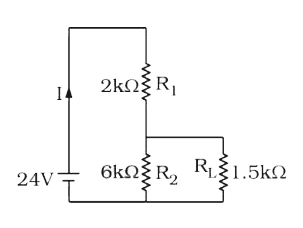
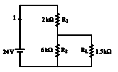
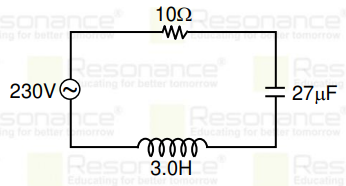
In the circuit shown in the figure, the ratio of the quality factor and the band width is ______s.
Video Solution
Text Solution
The correct Answer is:A
|
Answer
Step by step video, text & image solution for In the circuit shown in the figure, the ratio of the quality factor and the band width is ______s. by Physics experts to help you in doubts & scoring excellent marks in Class 12 exams.
Updated on:21/07/2023Topper's Solved these Questions
Similar Questions
Knowledge Check
In the circuit shown in figure, the ratio
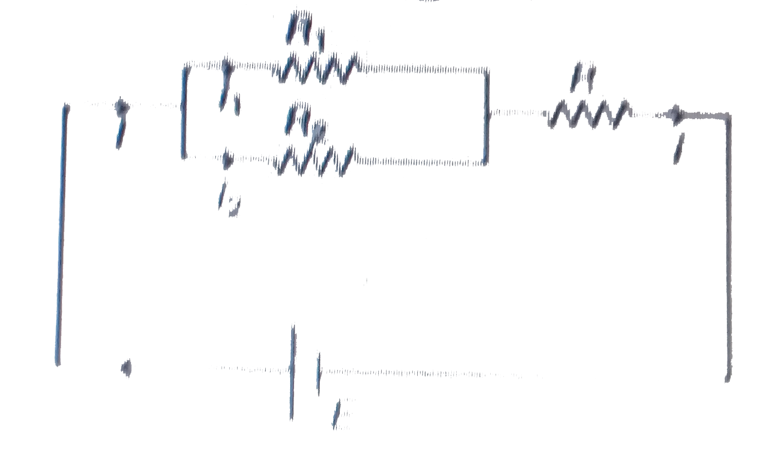 Ai1/i2 depends on R1 and R2 onlyBi/i1 depends on R1 and R2 onlyCi/i1 depends on E,R1,R2andRDi1/i2 depends on E,R1 and R2
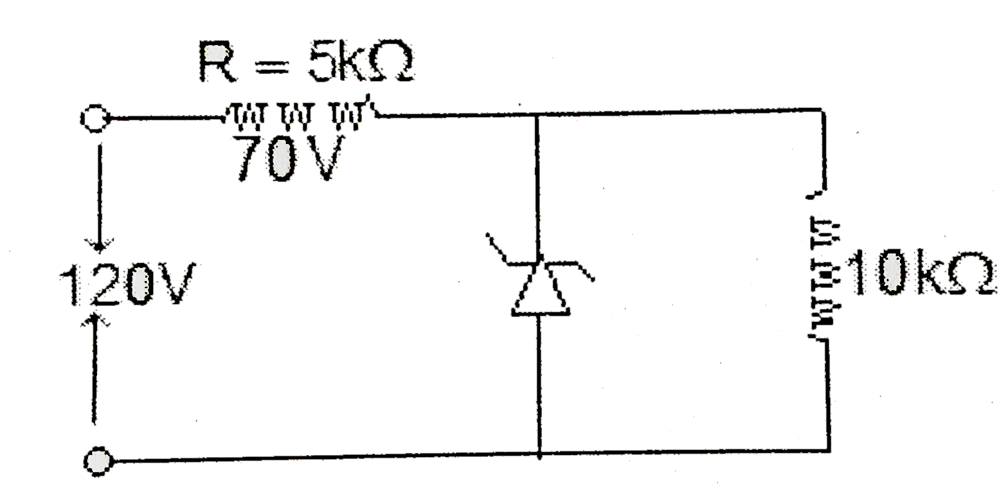
For the circuit shown in the figure:Acurrent through zener diode is 4 mA.Bcurrent through zener diode is 9 mACthe output voltage is 50 VDthe output voltage is 40 VFor the circuit shown in the figure :
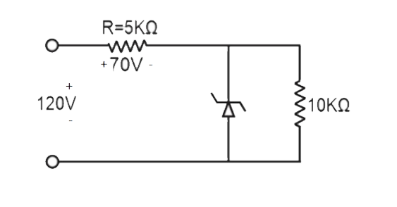 ACurrent through Zener diode is 4 mABCurrent through Zener diode is 9 mACThe output voltage is 60 VDThe output voltage is 40 V

