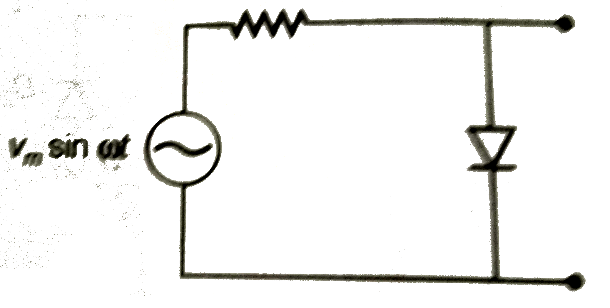
The output in the circuit of figure is taken across a capacitor. It is as shown in figure

A

B

C

D

Video Solution
Text Solution
The correct Answer is:C
For ve half D ON
For half D OFF
In ve half cycle, capacitor charges but in half it discharges very slowly because
Time constant
|
Topper's Solved these Questions
- ELECTRONICSBOOK - ERRORLESSCHAPTER - ELECTRONICSEXERCISE - NCERT Based Questions (Junction Transistor)
29 Videos
- ELECTRONICSBOOK - ERRORLESSCHAPTER - ELECTRONICSEXERCISE - NCERT Based Questions (Digital Electronics)
23 Videos
- ELECTRONICSBOOK - ERRORLESSCHAPTER - ELECTRONICSEXERCISE - Assertion & Reason
26 Videos
- ELECTRON, PHOTON, PHOTOELECTRIC EFFECT & X -RAYBOOK - ERRORLESSCHAPTER - ELECTRON, PHOTON, PHOTOELECTRIC EFFECT & X -RAYEXERCISE - ASSERTION & REASON
27 Videos
- ELECTROSTATICSBOOK - ERRORLESSCHAPTER - ELECTROSTATICSEXERCISE - ASSERTION & REASON
25 Videos
Similar Questions
Knowledge Check
The output of the given circuit in figure:
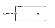 Awould be zero at all times.Bwould be like a half wave rectifier with positive cycles in output.Cwould be like a half wave rectifier with negative cycles in output.Dwould be like that of a full wave rectifier.
The output of the given circuit in Figure
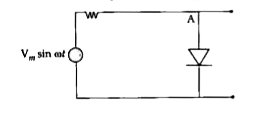 Awould be zero at all times.Bwould be like a half wave rectifier with positive cycles in output.Cwould be like a half wave rectifier with negative cycles in output.Dwould be like that of a full wave rectifier.
The output of the given circuit in figure given below,
 Awould be zero at all timesBwould be like a half wave rectifier with positive cycles in outputCwould be like a half wave rectifier with negative cycles in ouputDwould be like that of a full wave reactifier.
A capacitor is connected to a variable source of potential. Current flowing in the circuit and potential across the plates of capacitor at time t are shown in figure.

Capacity of the capacitor is
View SolutionA capacitor is connected to a variable source of potential. Current flowing in the circuit and potential across the plates of capacitor at time t are shown in figure.

At t=2s, energy is stored in the capacitor at a rate of
View SolutionThe output Y of the logic circuit as shown in figure is

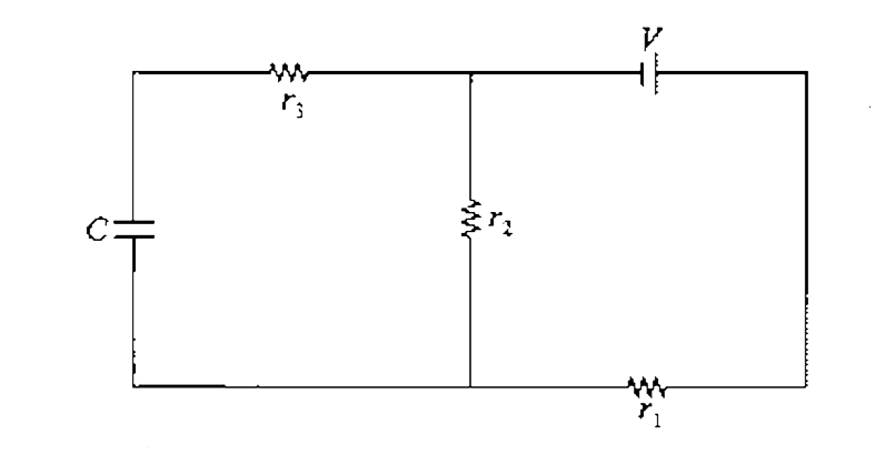
View SolutionIn the circuit shown in figure, the final voltage drop across the capacitor C is :
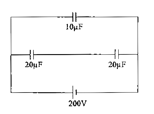
View SolutionIn the circuit shown in figure, charge on 10μF capacitor is given as
View Solution


