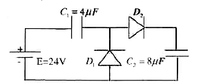
In the circuit shown, the potential drop across each capacitor is (assuming the two diodes are ideal)
Video Solution
Text Solution
The diode D1 is reverse biased (open circuit), but the diode D2 is forward biased (short circuit).
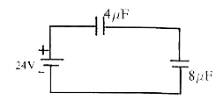
∴ the potential of the battery divides across the two capacitors in the inverse ratio of their capacities.
i.e.,V1V2=C2C1=84=21
V1=23E=23×24=16V
V2=13E=13×24=8V
|
Topper's Solved these Questions
- SEMICONDUCTOR DEVICESBOOK - AAKASH SERIESCHAPTER - SEMICONDUCTOR DEVICESEXERCISE - EXERCISE -I (ENERGY BANDS AND CLASSIFICATION OF SOLIDS )
41 Videos
- SEMICONDUCTOR DEVICESBOOK - AAKASH SERIESCHAPTER - SEMICONDUCTOR DEVICESEXERCISE - EXERCISE -I (P-N JUNCTION DIODE)
30 Videos
- SEMICONDUCTOR DEVICESBOOK - AAKASH SERIESCHAPTER - SEMICONDUCTOR DEVICESEXERCISE - Problems (LEVEL-II)
9 Videos
- RAY OPTICSBOOK - AAKASH SERIESCHAPTER - RAY OPTICSEXERCISE - PROBLEMS ( LEVEL-II)
60 Videos
- UNITS AND MEASUREMENTBOOK - AAKASH SERIESCHAPTER - UNITS AND MEASUREMENTEXERCISE - PRACTICE EXERCISE
45 Videos
Similar Questions
Knowledge Check
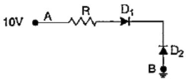
In figure , assuming the diodes to be ideal ,
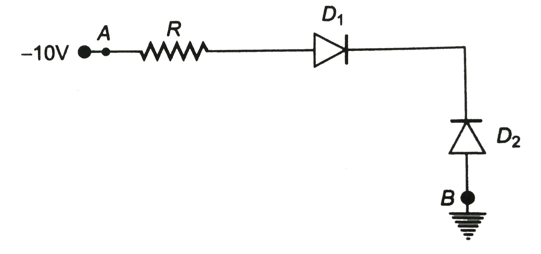 AD1 is forward biased and D2 is reverse biased and hence current flows from A to B.BD2 is forward biased and D1 is reverse biased and hence no current flows from B to A and vice versa.CD1andD2 are both forward biased and hence current flows from A to B.DD1andD2 are both reverse biased and hence no current flows from A to B and vice versa
In the circuit shown in figure potential difference across
View SolutionIn figure , assuming the diodes to be ideal ,

View SolutionIn figure , assuming the diodes to be ideal ,

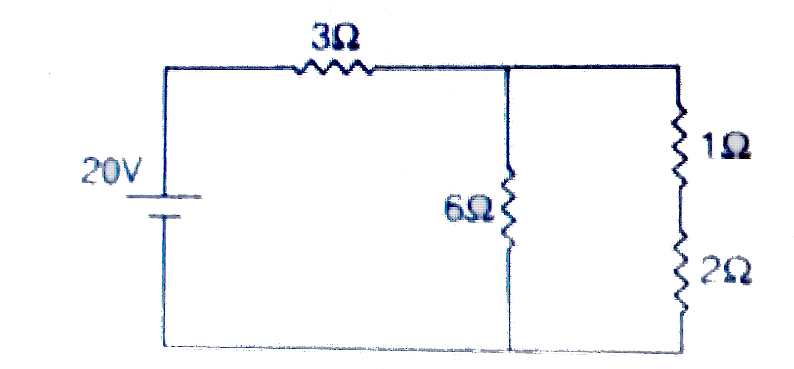
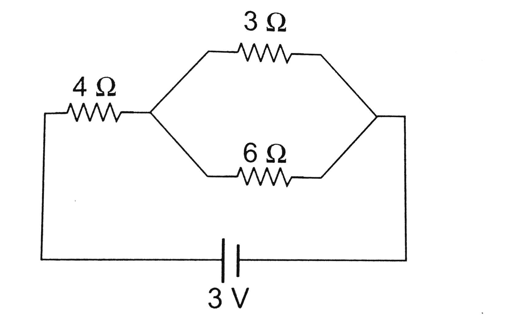
View SolutionThe potential drop across the 3Ω resistor is
View SolutionIn figure, assuming the diodes to be ideal,
View SolutionIn the given circuit, with steady current, the potential drop across the capacitor must be
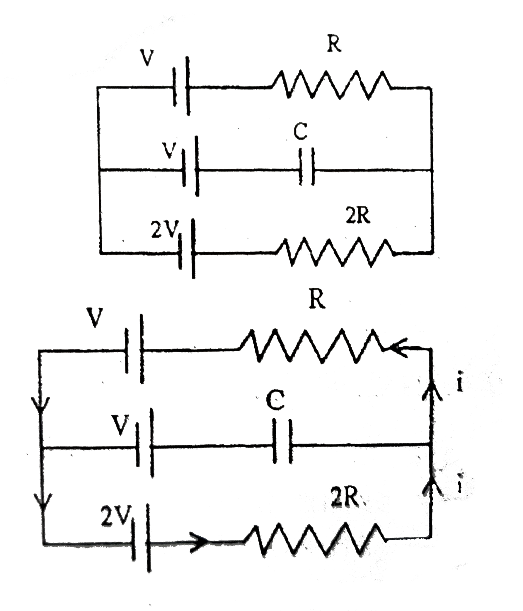
View SolutionIn the given circuit, with steady current, the potential drop across the capacitor must be
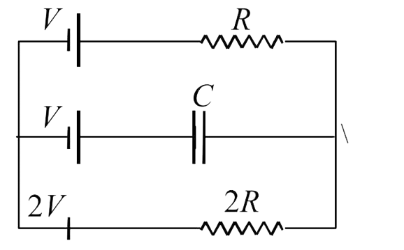
View Solution


