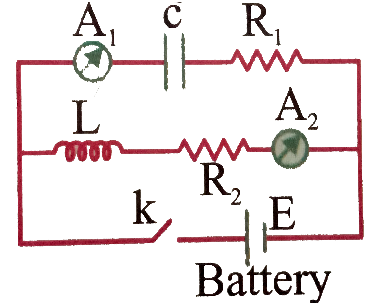
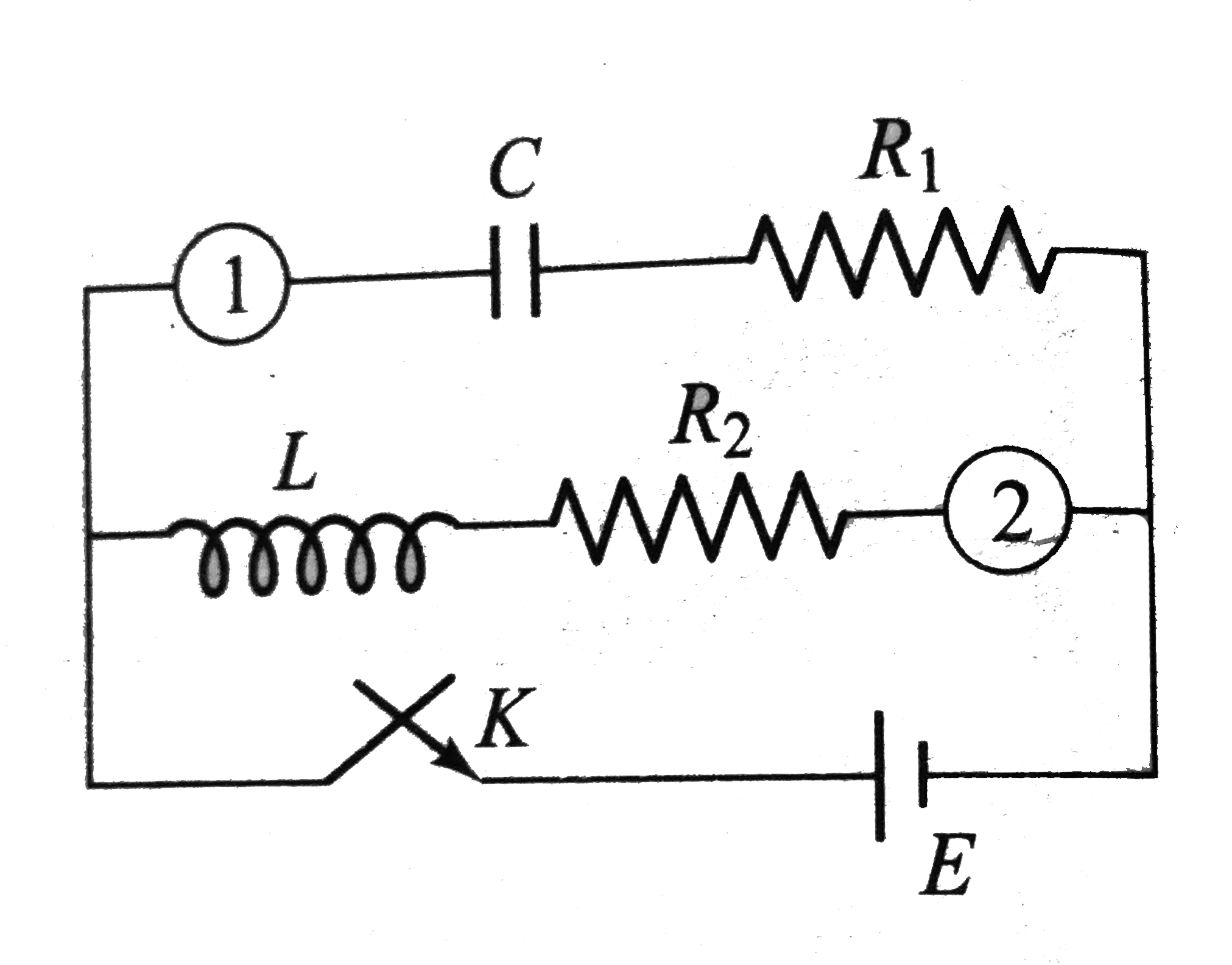
In a circuit inductance L and capacitance C are connected as shown in figures. A1 and A2 are ammeeters. When key K is pressed to complete the circuit, then just after closing key(K), the reading of current wil be

At t = 0 capacitor offers zero resistance and acts like a short circuit. While inductor offers infinite resistance and it acts like an open circuit. Therefore no current flow through inductor branch and maximum current flows through capacitor branch. Hence reading of A2 is zero and reading A1 is given by ER1
Topper's Solved these Questions
- ELECTROMAGNETIC INDUCTIONBOOK - AAKASH SERIESCHAPTER - ELECTROMAGNETIC INDUCTIONEXERCISE - EXERCISE-IA
58 Videos
- ELECTROMAGNETIC INDUCTIONBOOK - AAKASH SERIESCHAPTER - ELECTROMAGNETIC INDUCTIONEXERCISE - EXERCISE-IB
18 Videos
- ELECTRIC FIELD AND POTENTIALBOOK - AAKASH SERIESCHAPTER - ELECTRIC FIELD AND POTENTIALEXERCISE - PROBLEMS (LEVEL-II)
26 Videos
- ELECTROMAGNETIC WAVESBOOK - AAKASH SERIESCHAPTER - ELECTROMAGNETIC WAVESEXERCISE - EXERCISE -II
22 Videos
Similar Questions
In a circuit inductance L and capacitance C are connected as shown in figure and A1 and A2 are ammeters. When key k is pressed to complete the circuit, then just after closing key k, the readig of A1 and A2 will be:
View SolutionIn the circuit given in tigure, 1 and 2 are ammeters. Just after key K is pressed to complete the circuit the reading will be
View SolutionIn the circuit of Fig. (1) and (2) are ammeters. Just after circuit K is pressed to complete the circuit, the reading is
View SolutionIn the circuit shown in figure C1=2C2. Capacitance C1 is charged to a potential of V. The current in the circuit just after the switch S is closed is

View SolutionTwo capacitors C1=C and C2=3C are connected as shown in figure, Initially, key K is open and capacitor C1 holds charge Q. After closing the key K, the charge on each capacitor at steady state will be
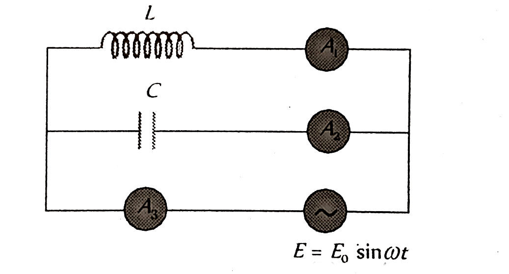
View SolutionAn inductor L and a capacitor C are connected in the circuit as shown in the figure. The frequency of the power supply is equal to the resonant frequency of the circuit. Which ammeter will read zero ampere
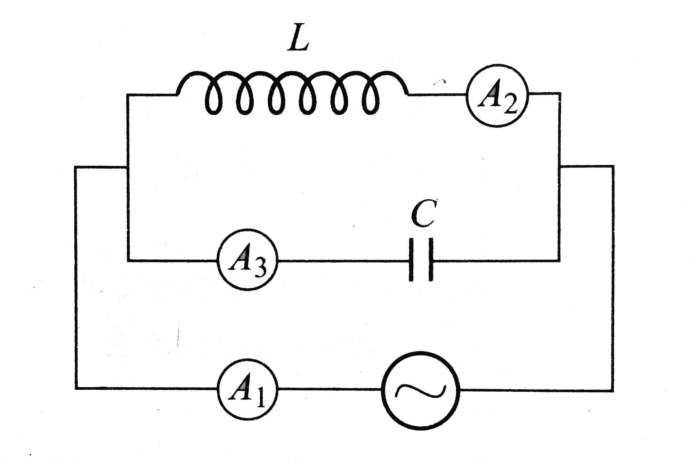
View SolutionFor the circuit shown in fig, the ammeter A2 reads 1.6A and ammeter (A3) reads 0.4A. Then
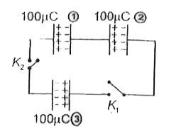
View SolutionThree identical charged capacitors each of capacitance 5 μF are connected as shown in figure. Potential difference across capacitor (3), long time after the swithces K1andK2 are closed , is
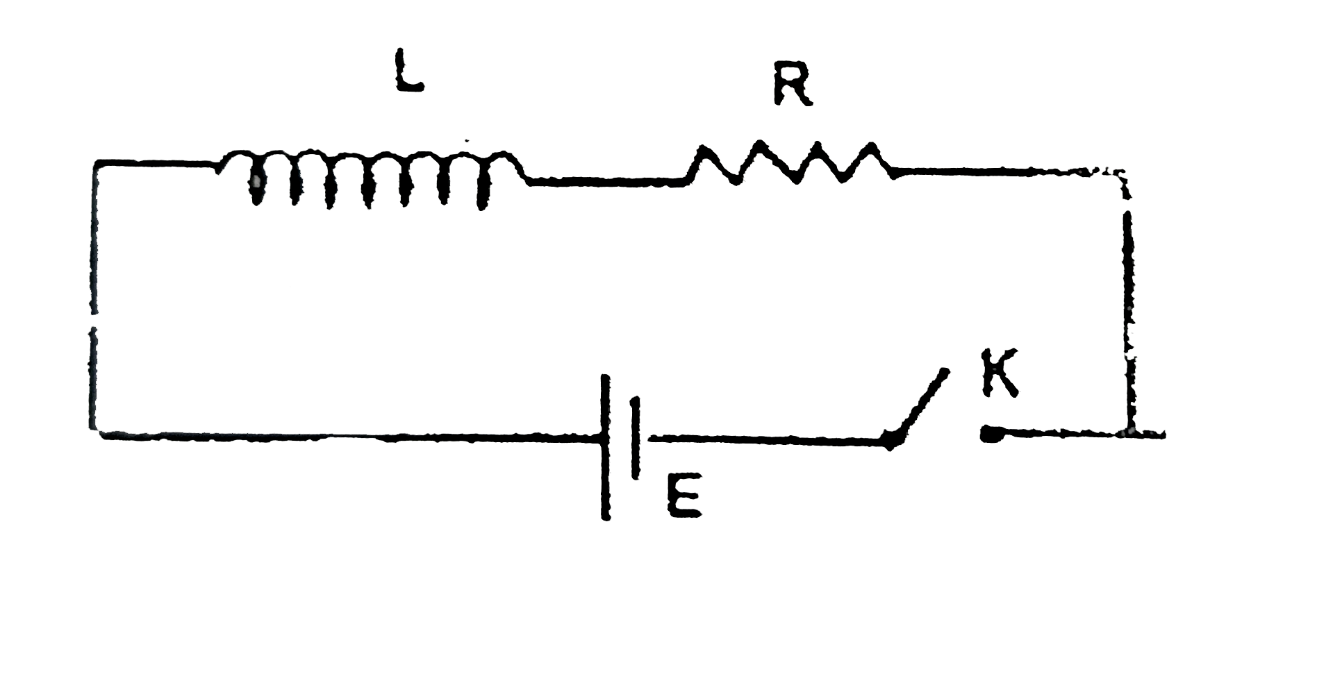
View SolutionShown in the figure is an R−L circuit. Just after the key (K) is closed
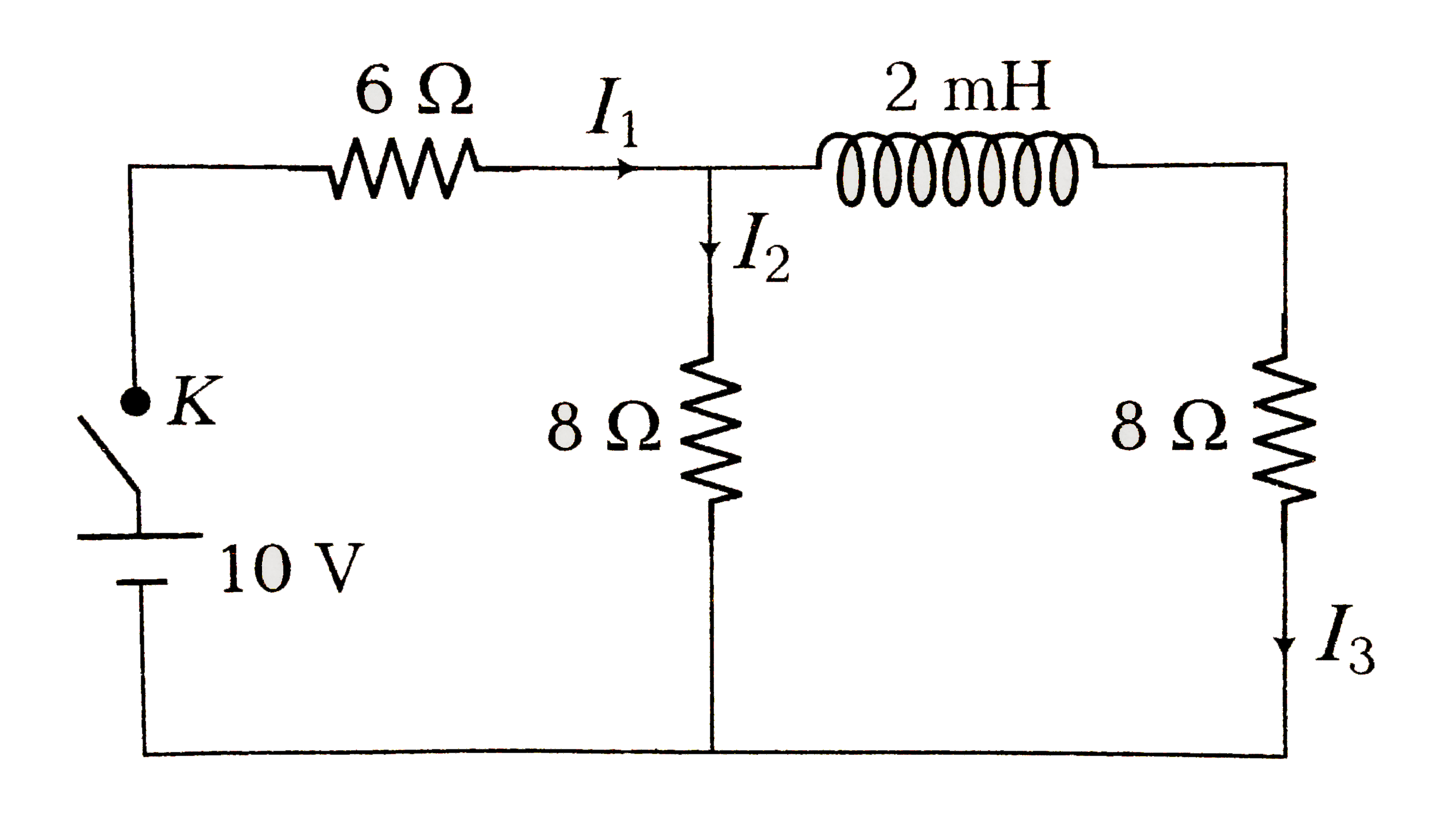
View SolutionIn the circuit shown in the figure, what is the value of I1 just after pressing the key K?
View Solution

