Passage :
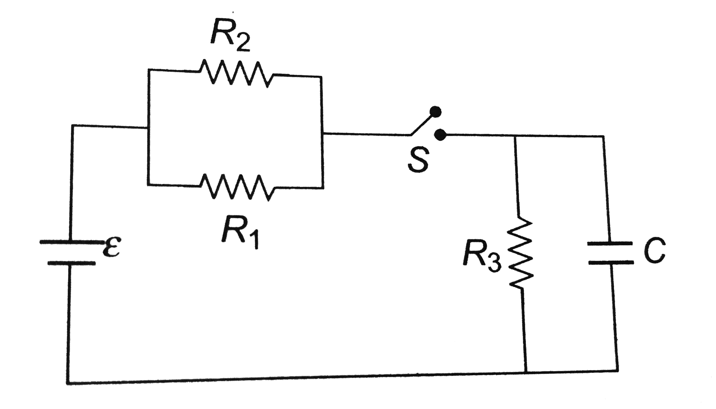
Suppose the switch S has been sufficiently long time for the capacitor to become fully charged. Find (where R1=12kΩ,R2=15kΩ,R3=5kΩ)

The steady-state current through each resistor
0.3s
0.1386 s
0.693 s
0.367 s
The correct Answer is:B
Step by step video & image solution for Passage : Suppose the switch S has been sufficiently long time for the capacitor to become fully charged. Find (where R_(1)=12kOmega, R_(2)=15kOmega, R_(3)=5kOmega) The steady-state current through each resistor by Physics experts to help you in doubts & scoring excellent marks in Class 12 exams.
Updated on:21/07/2023Topper's Solved these Questions
- CURRENT ELECTRICITYBOOK - AAKASH SERIESCHAPTER - CURRENT ELECTRICITYEXERCISE - PRACTICE SHEET (EXERCISE - I LEVEL-I (MAIN) (Straight Objective Type Questions))
7 Videos
- CURRENT ELECTRICITYBOOK - AAKASH SERIESCHAPTER - CURRENT ELECTRICITYEXERCISE - PRACTICE SHEET (EXERCISE - I LEVEL-II (ADVANCED) (Straight Objective Type Questions))
3 Videos
- CURRENT ELECTRICITYBOOK - AAKASH SERIESCHAPTER - CURRENT ELECTRICITYEXERCISE - LECTURE SHEET (EXERCISE-VII LEVEL-II (ADVANCED) (Straight Objective Type Questions))
5 Videos
- CURRENT ELECTRICITYBOOK - AAKASH SERIESCHAPTER - CURRENT ELECTRICITYEXERCISE - PROBLEMS (LEVEL-II)
27 Videos
- DUAL NATURE OF RADIATION AND MATTERBOOK - AAKASH SERIESCHAPTER - DUAL NATURE OF RADIATION AND MATTEREXERCISE - PRACTICE EXERCISEX
42 Videos
Similar Questions
Passage :
Suppose the switch S has been sufficiently long time for the capacitor to become fully charged. Find (where R1=12kΩ,R2=15kΩ,R3=5kΩ)

In the above question the charge on the capacitor is
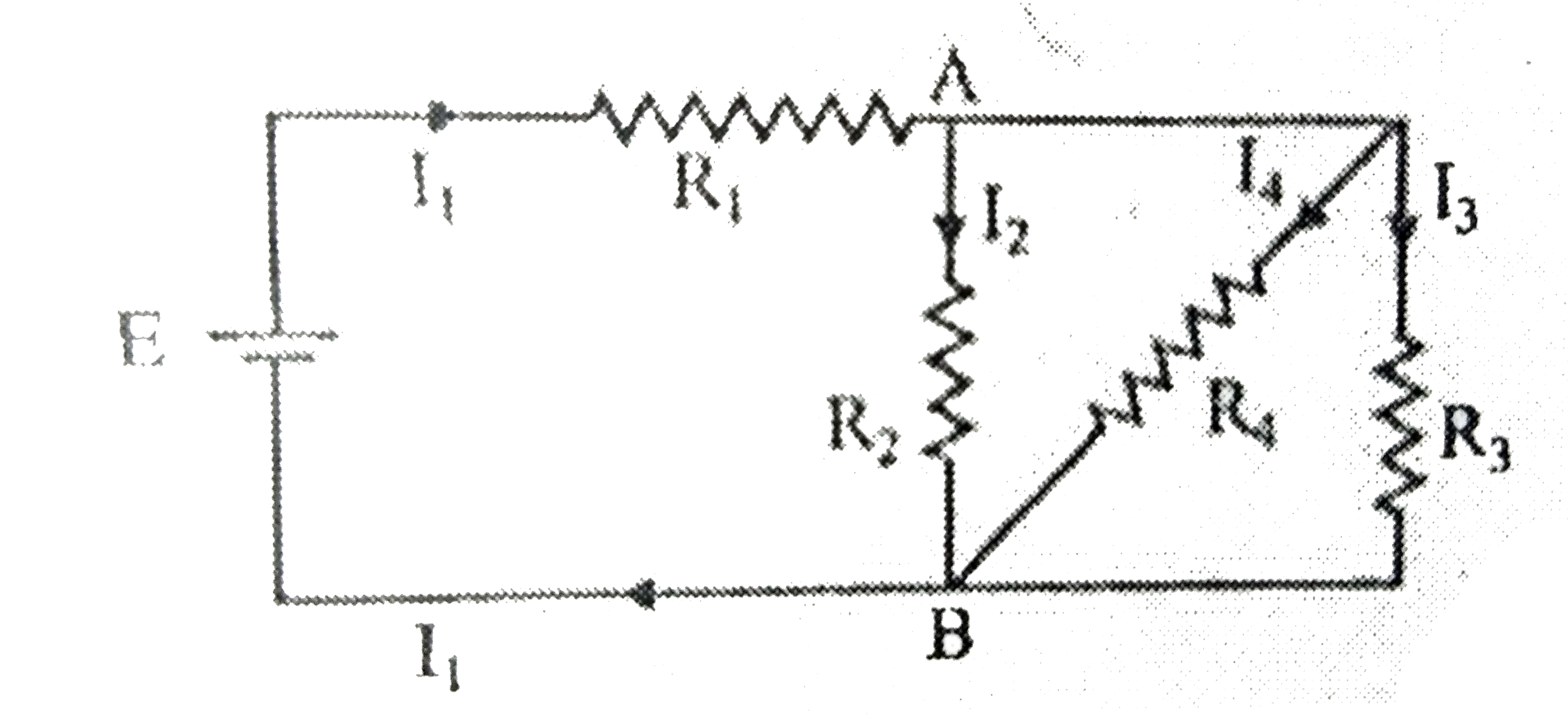
View SolutionIn the circuit shown, R1=4Ω,R2=R3=15Ω,R4=30ΩandE=10V. Caculate the equivalent resistance of te circuit and the current in each resistor.
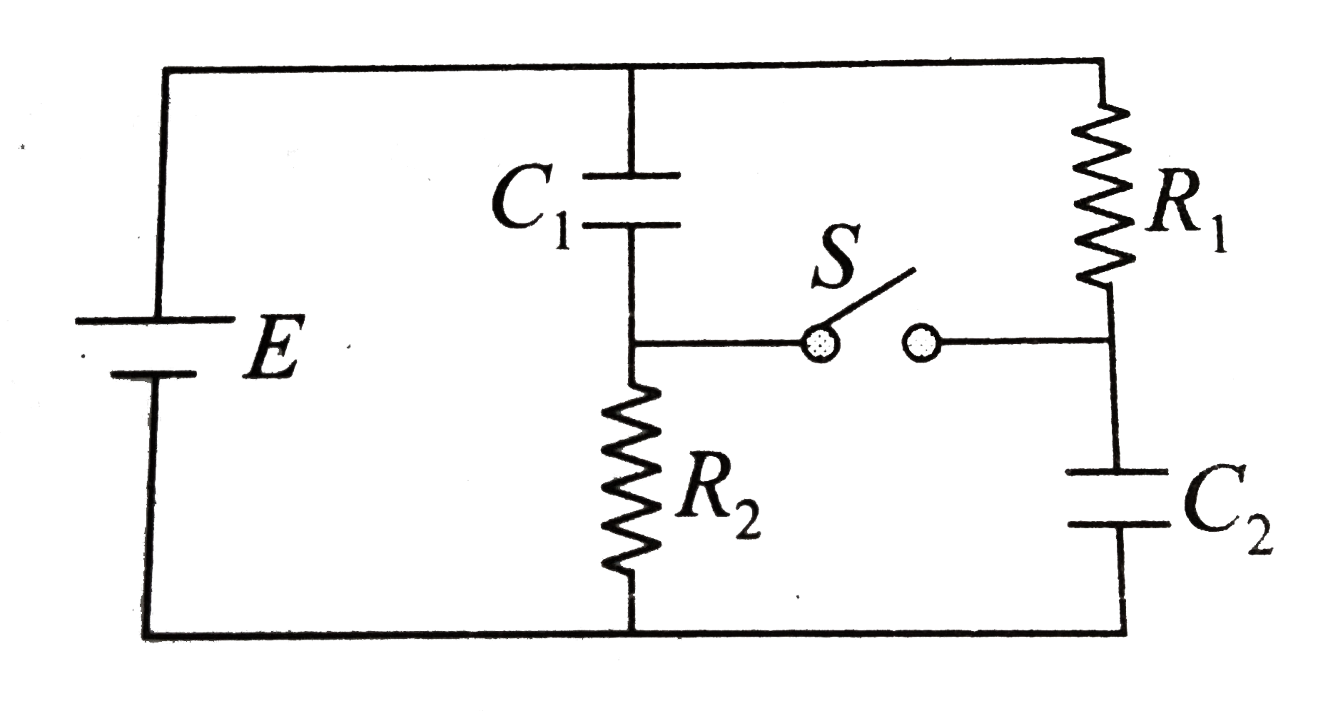
View SolutionThe switch S has been closed for long time and the electric circuit shown caries a steady current. Let C1=3.0μF,C2=6.0μF,R1=4.0kΩ,andR1=7.0kΩ
The power dissipated in R2 is 2.8 W.
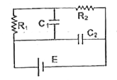
View SolutionIn the circuit shown in figure, R(1)=1Ω,R2=2Ω,C1=1μF,C2=2μF and E=6V. Calculate charge on each capacitor in steady state
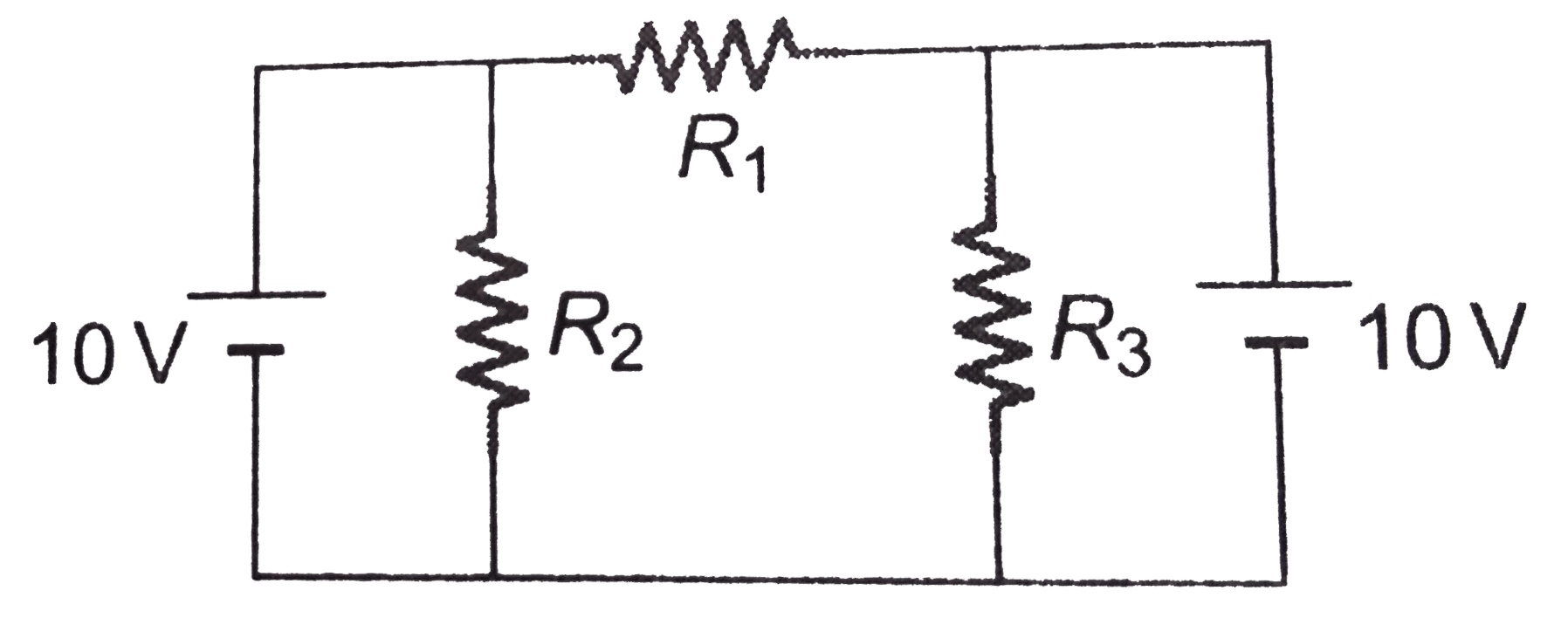
View SolutionIn the curcuit shown in figure R1=R2=R3=10Ω. Find the currents through R1 and R2
View SolutionThe circuit shown in the figure consists of a battery of emf ε=10V , a capacitor of capacitance C=1.0μF and three resistors of value R1=2Ω,R2=2Ω and R3=1Ω, Initially the capacitor is completely uncharged and the switch S is open. The switch S is closed at t=0. Then
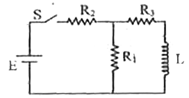
View SolutionFor the circuit shown E=50 V R1=10Ω,R2=20Ω,R3=30Ω L = 2.0 mH . The current through R1 and R2 are ________ . immediate after the switch is closed.
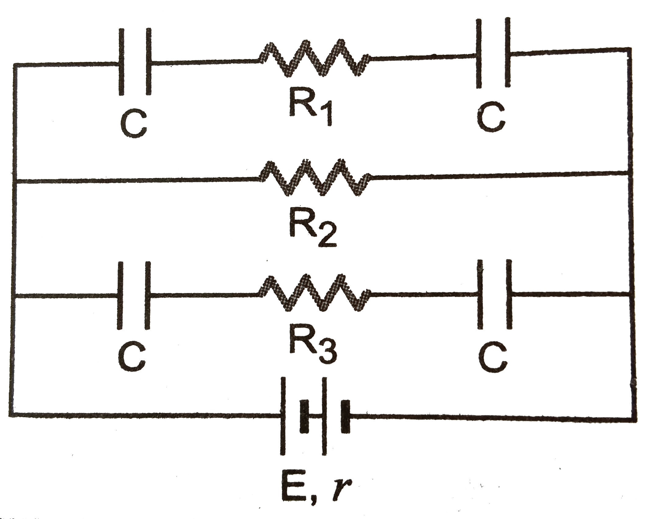
View SolutionIn Fig, E=5 volt , r=1Ω,R2=4Ω,R1=R3=1Ω and C=3μF. Then the numbercal value of the charge on each plate of the capacitor is
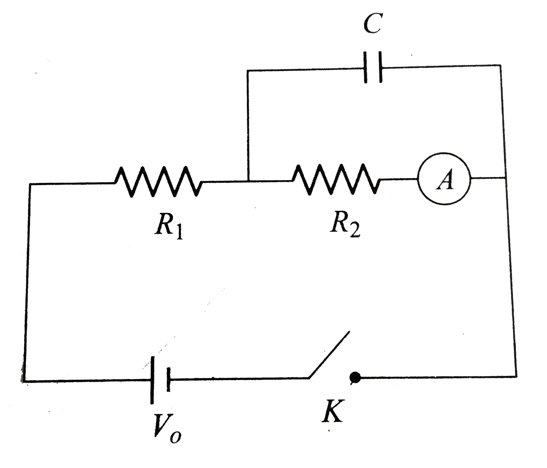
View SolutionIn the connection shown in the figure, initially the switch K is open and the capacitor is uncharged. Then the switch is closed, and the capacitor is charged up to the steady state and the switch is opened again. Determine the values indicated by the values indicated by the ammeter.
[GivenV0=30V,R1=10kΩ,R2=5kΩ]
 .
.
A long time after the switch was closed.
View SolutionIn the connection shown in the figure, initially the switch K is open and the capacitor is uncharged. Then the switch is closed, and the capacitor is charged up to the steady state and the switch is opened again. Determine the values indicated by the values indicated by the ammeter.
[GivenV0=30V,R1=10kΩ,R2=5kΩ]
 .
.
A long time after the switch was closed.
View Solution
