Consider the circuit shown in the figure. Taking the potential to be zero at the negative terminal of the battery :
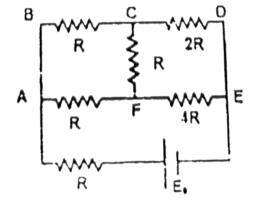
(∑i=0atp∮F)
(V_(F)-V_(c))/(R)+(V_(F)-V_(B))/(R)+(V_(R))/(4R)=0ldots(1)∴(VA=VB)(2i = 0 at point F)
AlsoVC−VFR+VC−VBR+Vc2R=0...(2)
Using (1) & (2)VFVC=1413∴k=7
Similar Questions
Consider the circuit shown in the figure. The current I3 is equal to
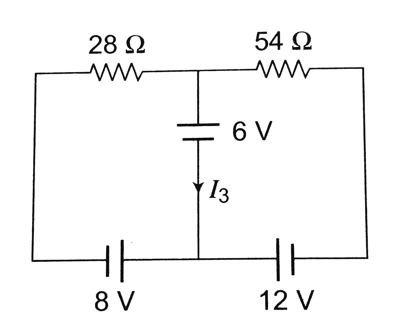
View SolutionConsider the circuit shown in the figure.
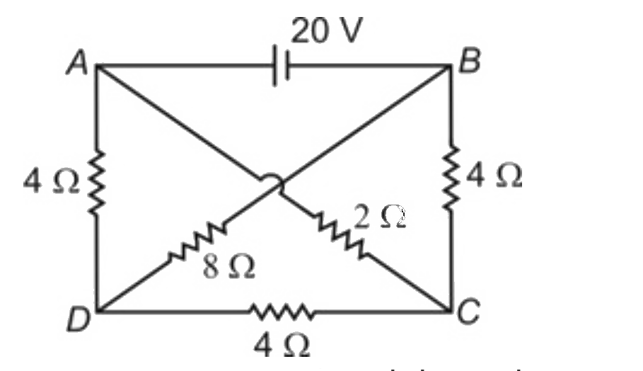
Which of the following statements are correct ?
View SolutionIn the circuit shown in the figure, if potentail at point A is taken to be zero, the potential at point B is
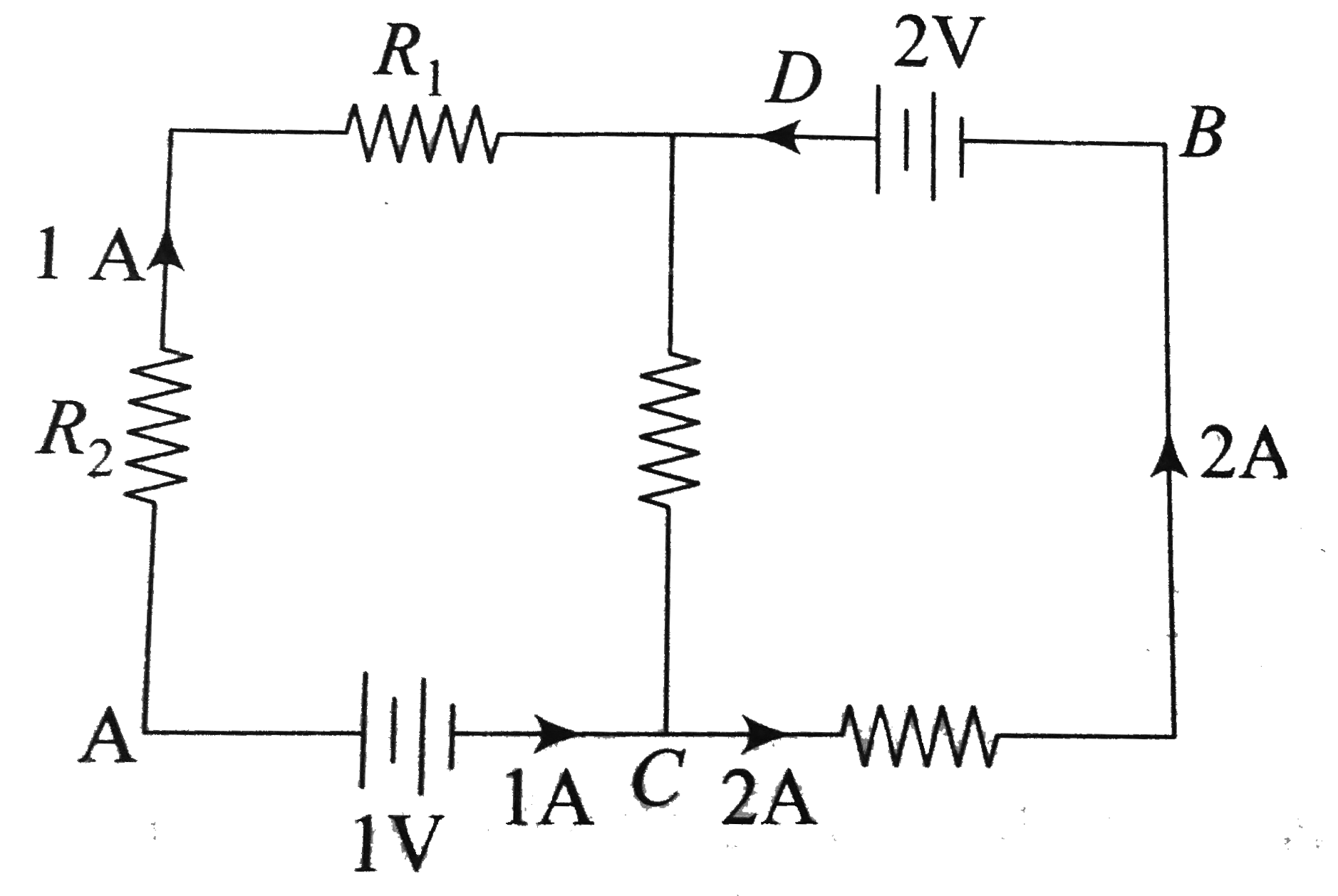
View SolutionIn the circuit shown in figure potential difference across
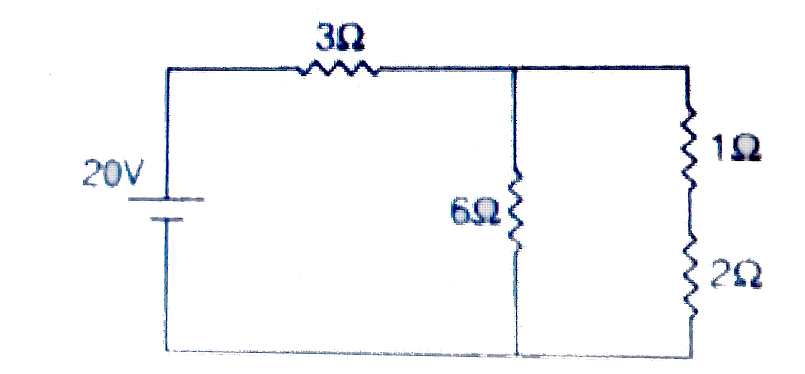
View SolutionConsider circuit as shown in figure. The current through wire AB is
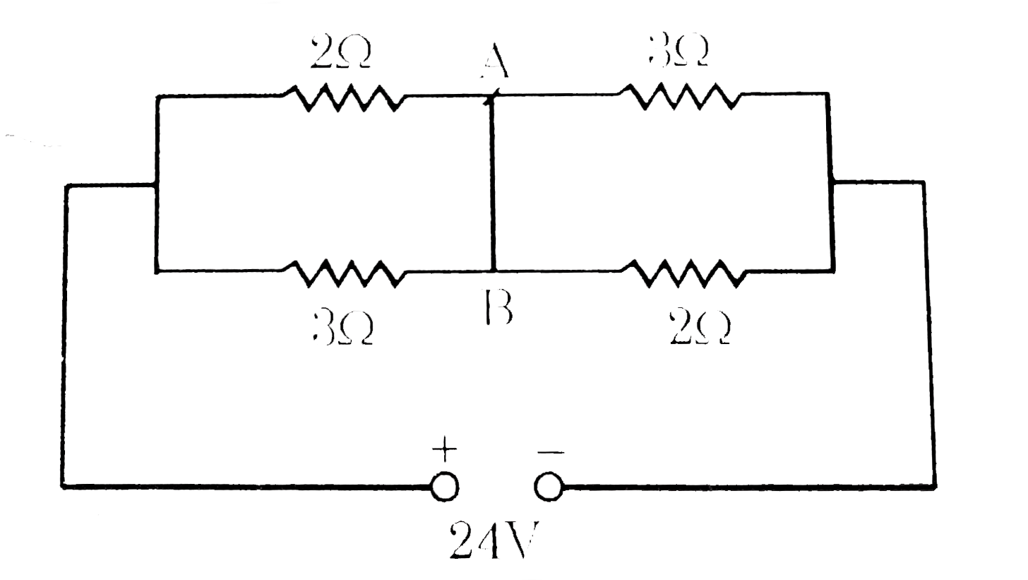
View SolutionIn the circuit shown in the figure, in steady state:
The current drawn from the battery is
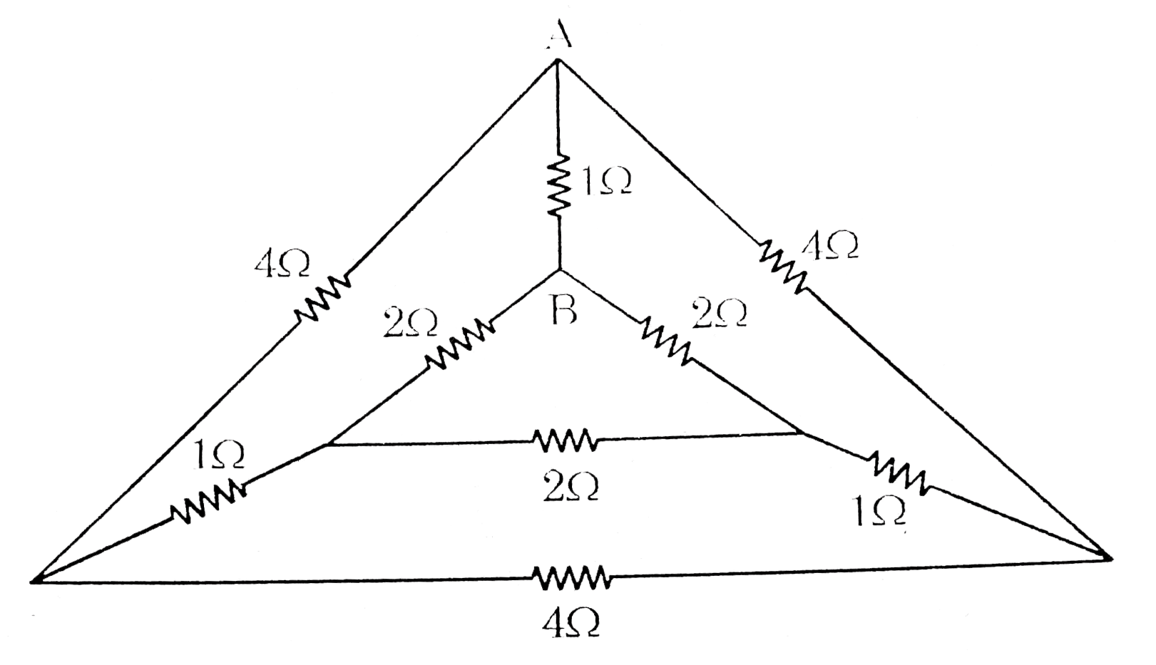
View SolutionConsider the circuit as shown in figure. The equivalent resistance between A and B is
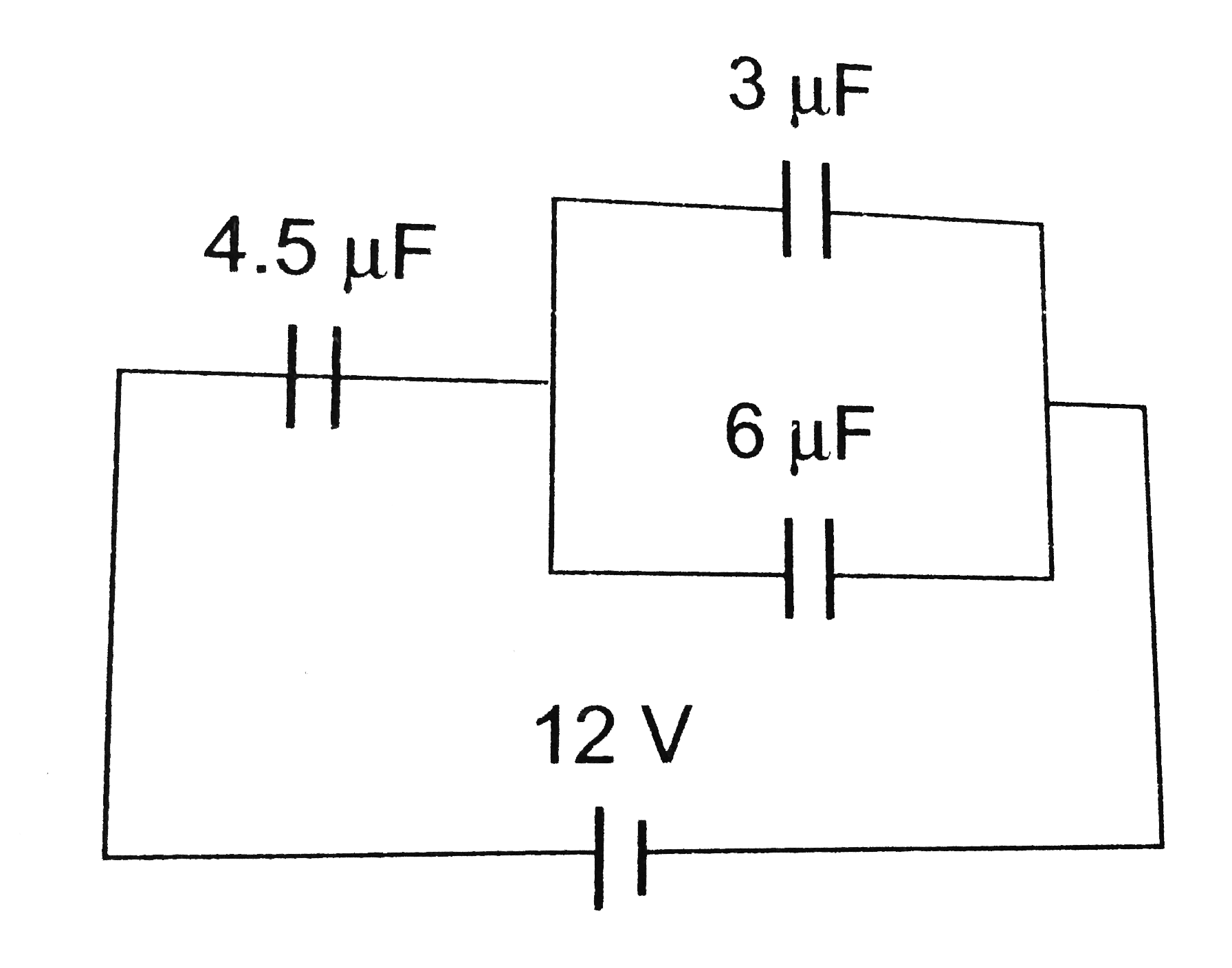
View SolutionIn the circuit shown in the figure, the potential difference across the 4.5μF capacitor is
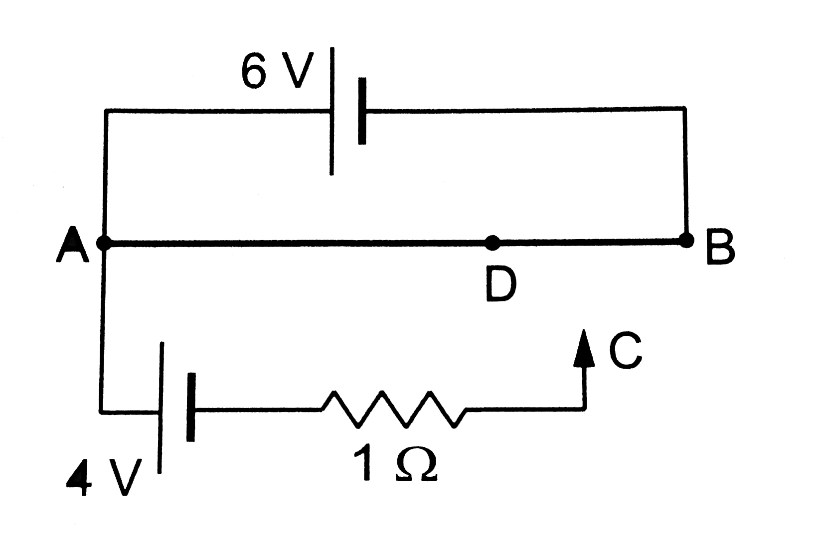
View SolutionA 6-volt battery of negligible internal resistance is connected across a uniform wire AB of length 100cm. The positive terminal of another battery of emf 4V and internal resistance 1(Ω)is joined to the point A as shown in figure.Take the potential at B to be zero. (a) What are the potentials at the poits A and C ? (b) At which point D of the wire AB, the potential is equal to the potential at C?(c ) If the point C and D are connected by a wire, what will be the current through it ? (d) If the 4V battery is replaced by 7.5V battery,wht would be the answer of parts (a) and (b) ?
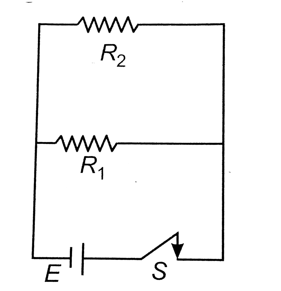
View SolutionConsider the circuit shown in figure. The current through the battery a long time after the switch S is closed is:
View Solution
