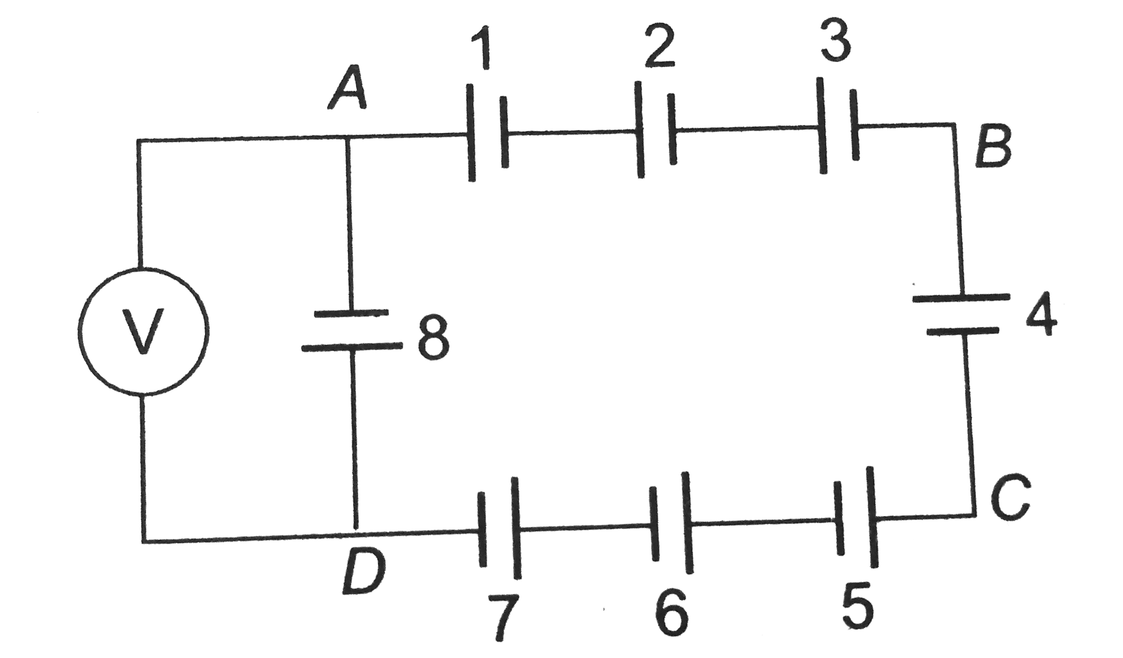
In the circuit shown in figure , each battery is 5 V and has an internal resistance of 0.2Ω.
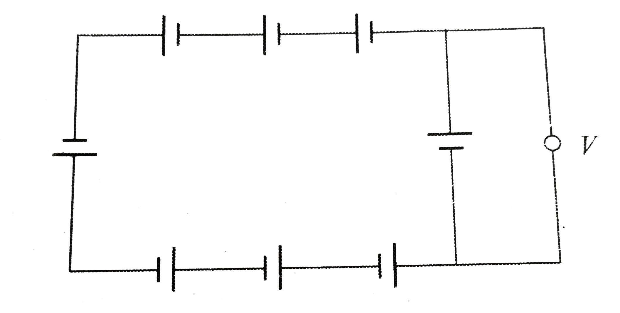
the reading in the ideal voltmeter V is ………..V.
Current in the circuit i=8×58×03=25A (counter clockwise)
Therefore, PD across the terminals of the battery , V=E−ir=5−(25)(0.2)=0
Topper's Solved these Questions
- DC CIRCUITBOOK - VMC MODULES ENGLISHCHAPTER - DC CIRCUITEXERCISE - LEVEL-1 JEE MAIN ARCHIVE
93 Videos
- CURRENT ELECTRICITYBOOK - VMC MODULES ENGLISHCHAPTER - CURRENT ELECTRICITYEXERCISE - IN-CHAPTER EXERCISE-F
10 Videos
- DYNAMICS OF A PARTICLEBOOK - VMC MODULES ENGLISHCHAPTER - DYNAMICS OF A PARTICLEEXERCISE - JEE Advance (Archive) Level - II (SINGLE OPTION CORRECT TYPE )
31 Videos
Similar Questions
in the circuit shown in the figure, each battery is of 5 V and has an internal resistance of 0.2 Omega What is the reading of the ideal voltmeter V
View SolutionIn the circuit shown below, each battery is 5V and has an internal resistance of 0.2 ohm.
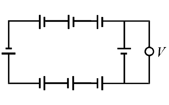
The reading in the ideal voltmeter V is .
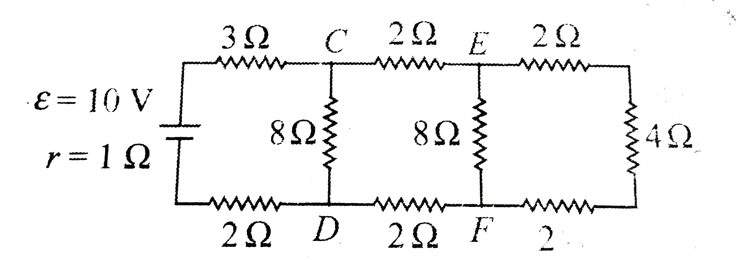
View SolutionIn the circuit shown in fig. the cell has emf 10V and internal resistance 1Ω
View SolutionIn the circuit shown below, E is a battery of emf 6 V and internal resistance 1Ω. Find the reading of the ammeter A. if it has negligible resistance :

View SolutionIn the circuit shown in figure ammeter and voltmeter are ideal. If E=4V,R=9Ω and r=1Ω then readings of ammeter and voltmeter are
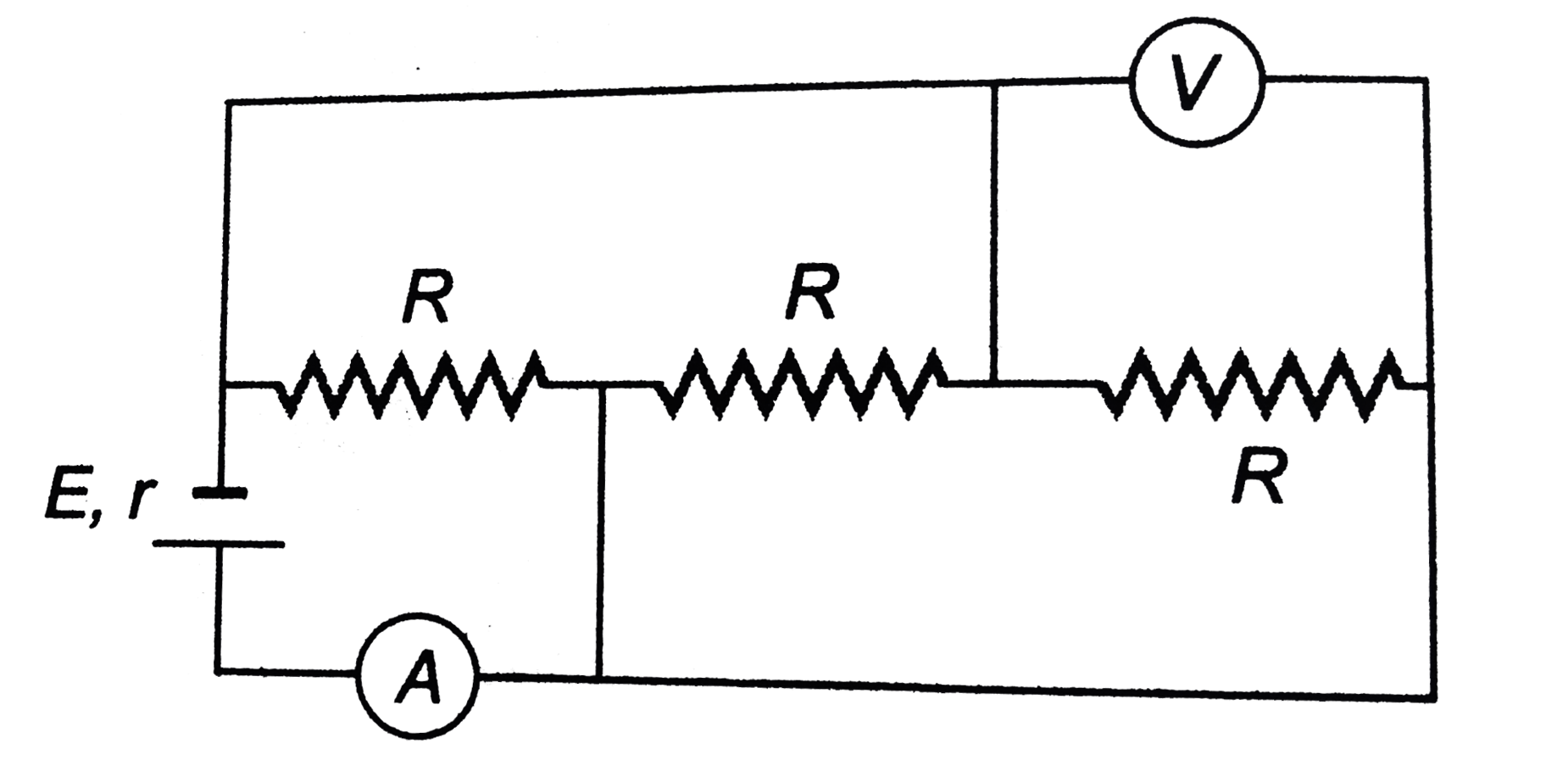
View SolutionIn the circuit shown in figure ammeter and voltmeter are ideal. If E=4V,R=9Ω and r=1Ω then readings of ammeter and voltmeter are

View SolutionEight cells marked 1 to 8, each of emf 5V and internal resistance 0.2Ω are connected as shown. What is the reading of ideal voltmeter ?
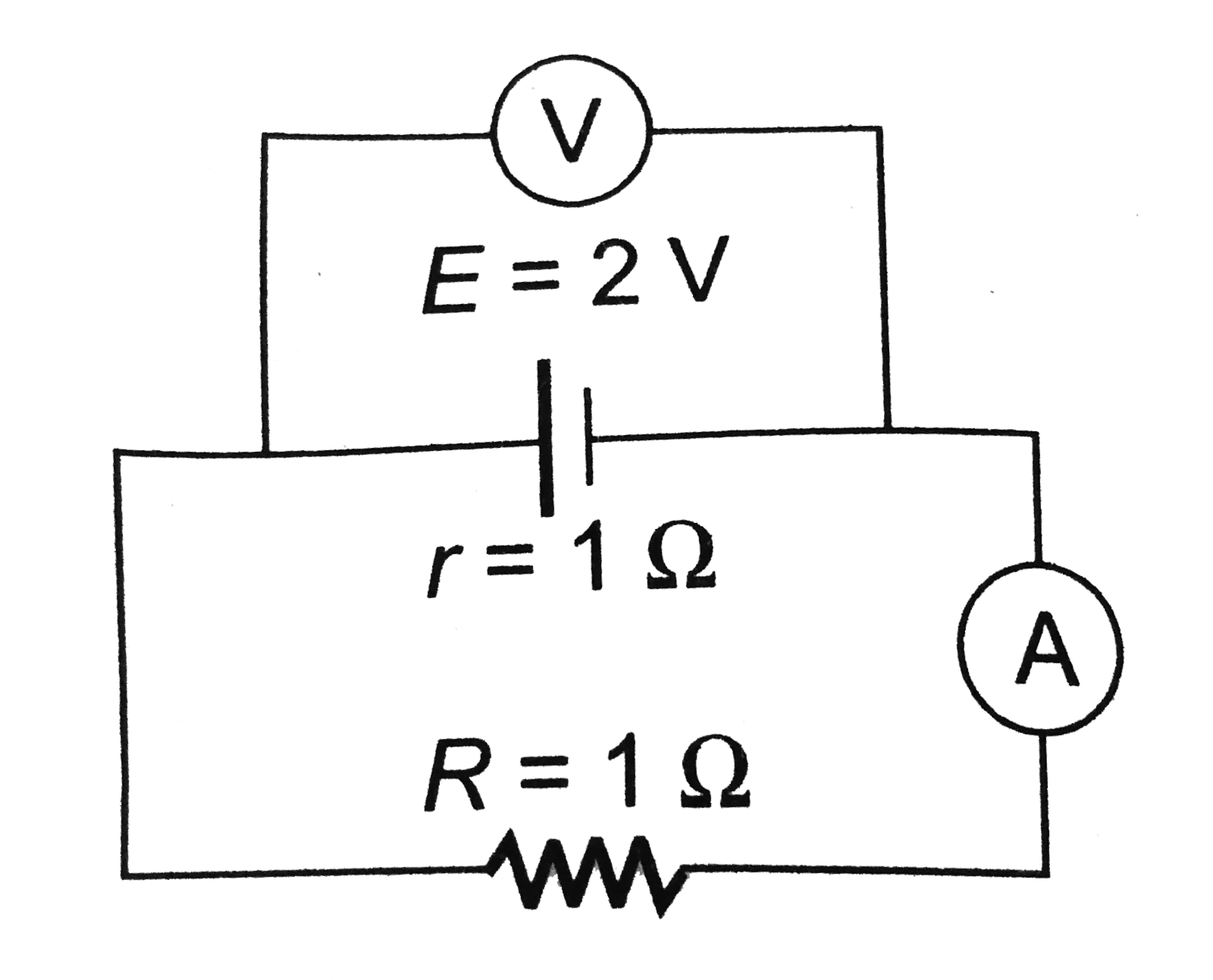
View SolutionAssetion : In the following circuit emf is 2V and internal resistance of the cell is 1Ω and R=1Ω, then reading of the voltmeter is 1V.
Reason : V=E−ir where E=2v,i=22=1A and r=1Ω
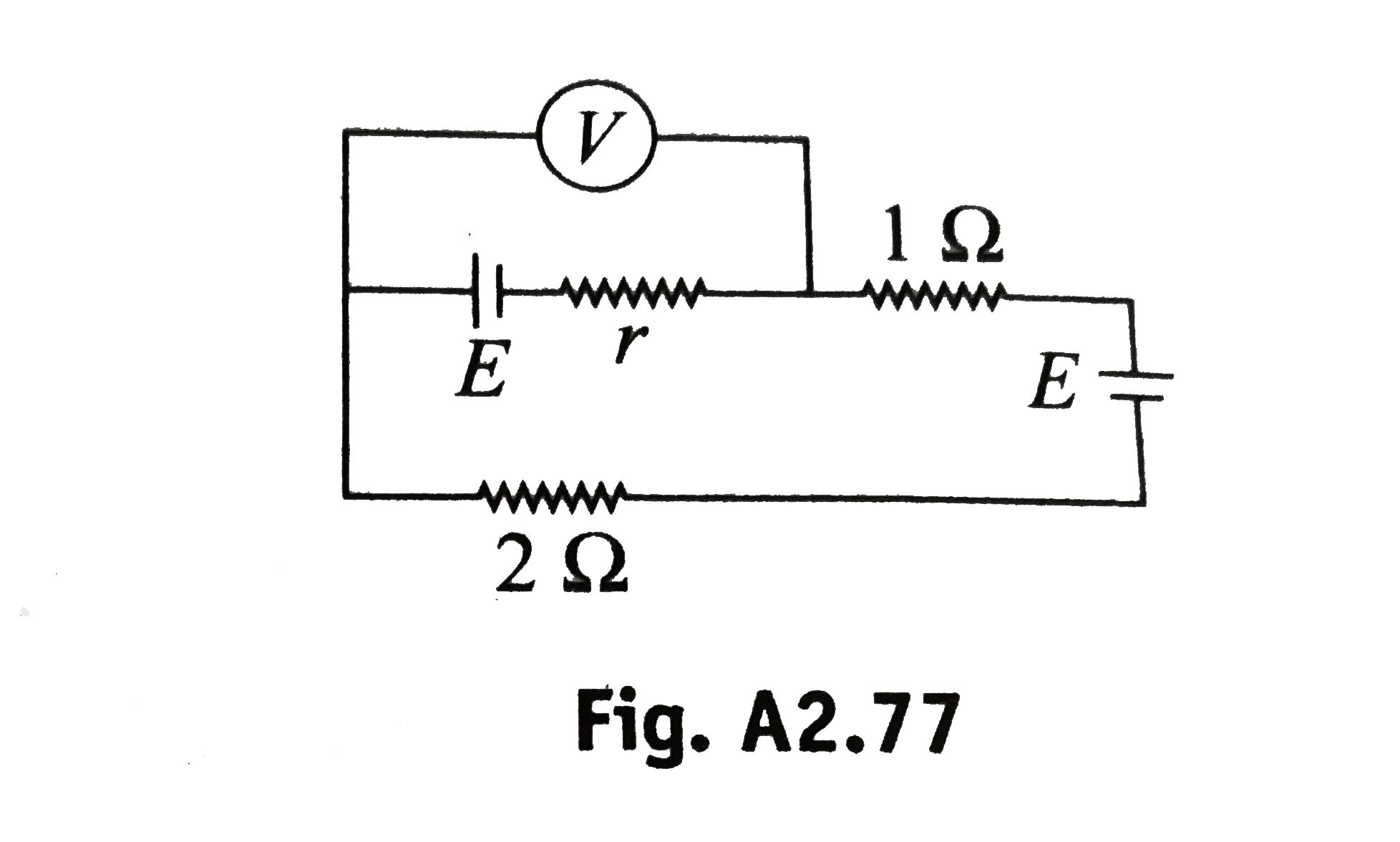
View SolutionIn the given circuit, the reading of ideal voltmeter is E/2. The internal resistance of the battery is
View SolutionIn the circuit shown below. The reading of the voltmeter V is

View Solution
