The galvanometer shown in the figure reads 3A, while the ideal voltmeter reads 24 volt. The value of R=7Ω. The galvanometer resistance is :

10Ω
5Ω
1Ω
20Ω
The correct Answer is:C
V=i(G+R)
or 24=3√G+7
or G=1Ω
Topper's Solved these Questions
- DAILY PRACTICE PROBLEMBOOK - RESONANCE ENGLISHCHAPTER - DAILY PRACTICE PROBLEMEXERCISE - DPP No.41
9 Videos
- DAILY PRACTICE PROBLEMBOOK - RESONANCE ENGLISHCHAPTER - DAILY PRACTICE PROBLEMEXERCISE - DPP No.42
20 Videos
- DAILY PRACTICE PROBLEMBOOK - RESONANCE ENGLISHCHAPTER - DAILY PRACTICE PROBLEMEXERCISE - DPP No.39
9 Videos
- CURRENT ELECTRICITYBOOK - RESONANCE ENGLISHCHAPTER - CURRENT ELECTRICITYEXERCISE - High Level Problems (HIP)
19 Videos
- ELECTRO MAGNETIC WAVESBOOK - RESONANCE ENGLISHCHAPTER - ELECTRO MAGNETIC WAVESEXERCISE - Exercise 3
27 Videos
Similar Questions
Knowledge Check
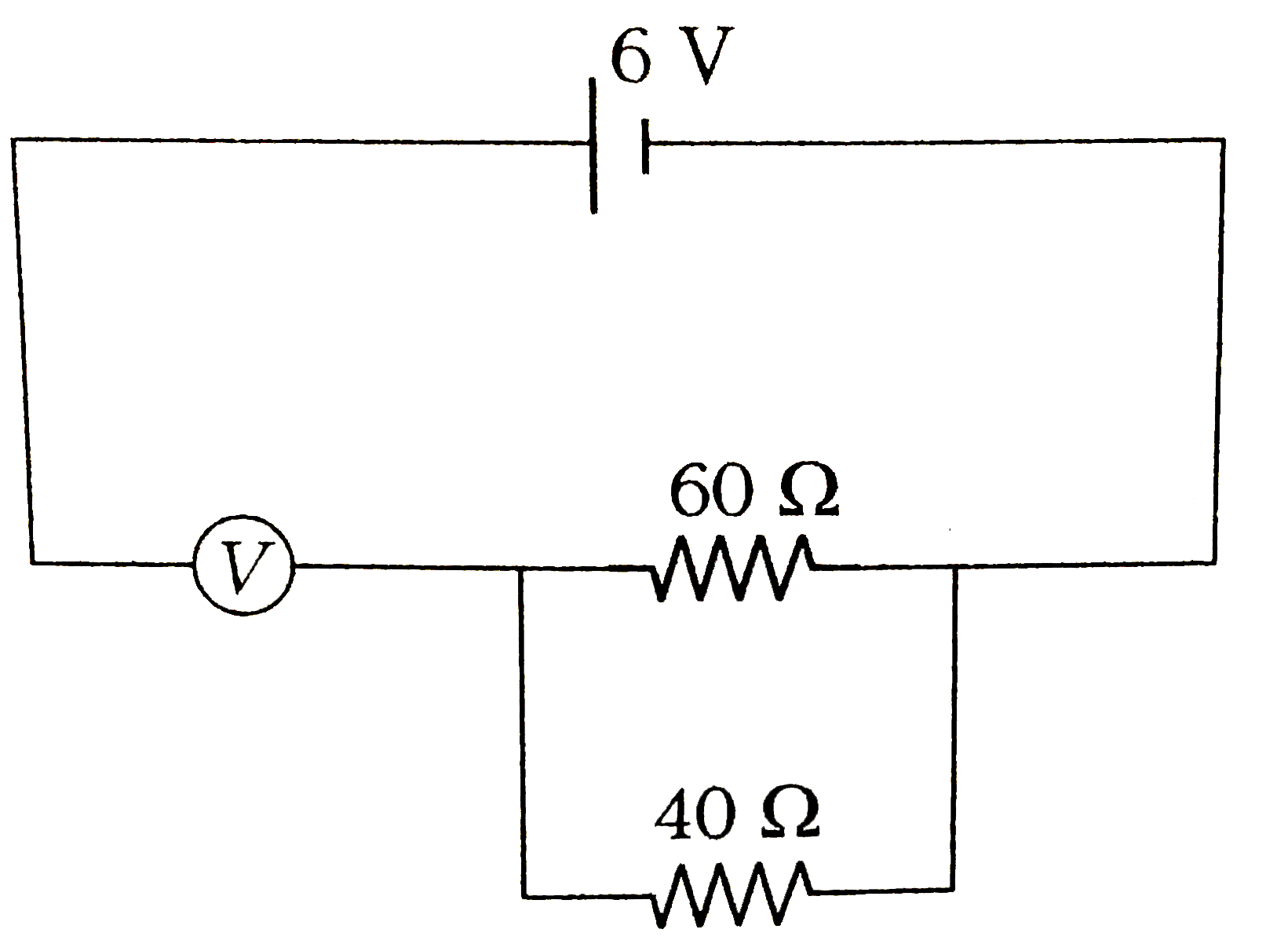
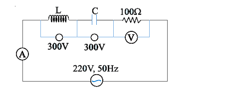
In the circuit shown in figure, what will be the reading of the voltmeter ?
 A300 VB900 VC200 VD400 V
Is correct. In the circuit shown in the figure, the voltmeter reading would be.
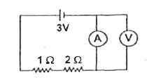
View SolutionIn the adjoining circuit diagram, the readings of ammeter and voltmeter are 2 A and 120 V, respectively. If the value of R is 75Ω, then the voltmeter resistance will be
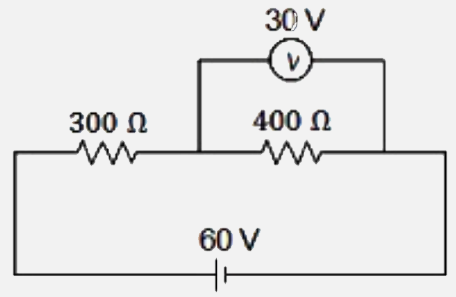
View SolutionIn the circuit figure, the voltmeter reads 30 V. The resistance of the voltmeter is
View SolutionA voltmeter reads the potential difference across the terminals of an old battery as 1.40V, while a potentiometer reads its voltage to be 1.55V. The voltmeter resistance is 280Ω.
View SolutionIn the circuit shown in figure, what will be the readings of voltmeter and ammeter?
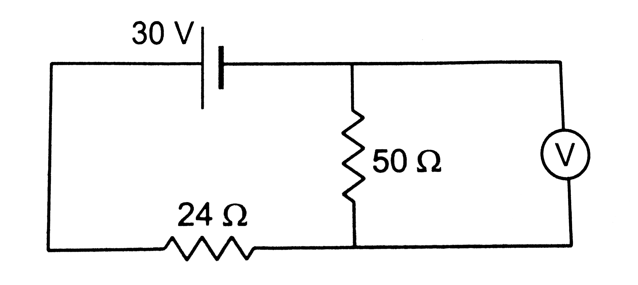
View SolutionThe voltmeter shown in figure reads 18V across the 50(Ω)resistor. Find the resistance of the voltmeter.
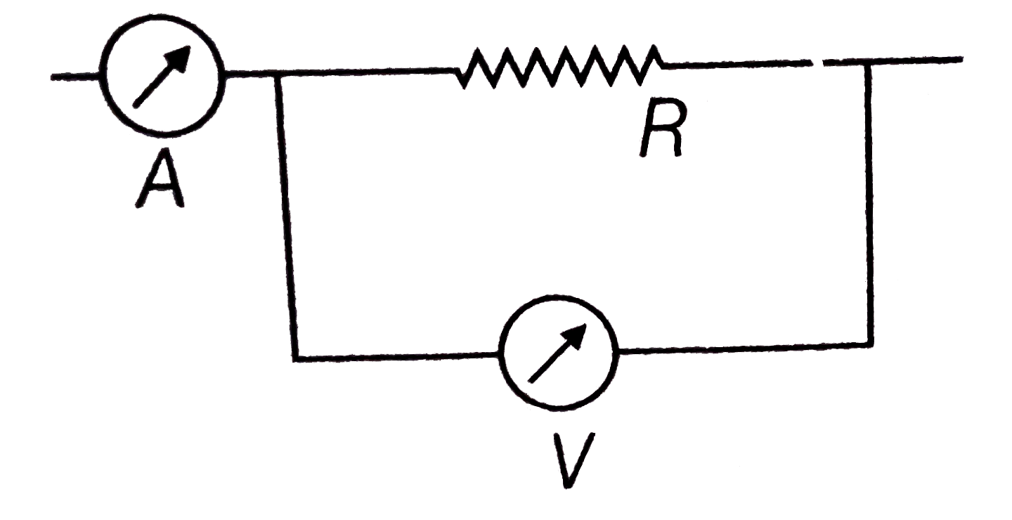
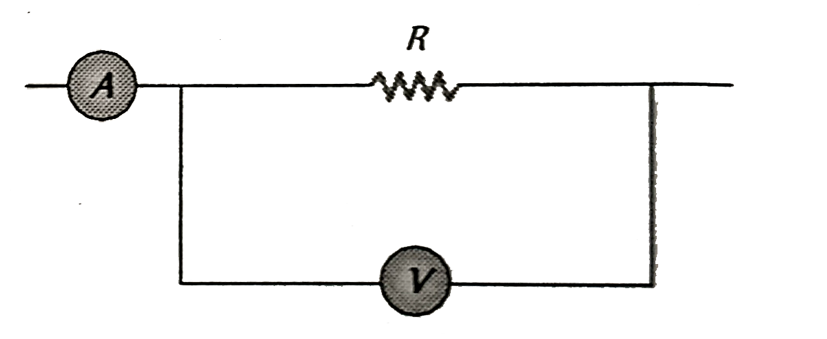
View SolutionThe ammeter A reads 2A and the voltmeter V reads 20V, the value of resistance R is (Assuming finite resistance's of ammeter and voltmeter)
View Solution

