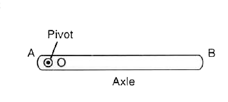
The figure alongside shows an axle AB pivoted at a point 0. Draw diagrams showing the point of application and direction of minimum force to rotate it (b) clockwise, and (ii) anticlockwise.

The diagrams given below show the force F to rotate the axle (i) clockwise, and (ii) anti-clockwise.

Topper's Solved these Questions
Similar Questions
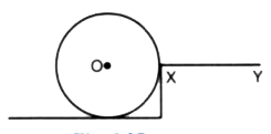
The adjacent diagram Fig 1.27 shows a heavy roller, with its axle at O, which is to be raised on a pavement XY. IF there is friction between the roller and pavement, show by an arrow on the diagram the point of application and the direction of force to be applied. If pivoted at O, now will it go up?

View SolutionDraw a ray diagram showing the formation of image of a point object by a plane mirror.
View SolutionA wooden block is placed on a table top. Name the forces acting on the block and draw a neat and labelled diagram to show the point of application and direction of these forces.
View SolutionDraw a diagram of a block and tackle system of pulleys having a velocity ratio of 5. in your diagram indicate clearly the points of application and the directions of the load L and effort E. also mark the tension T in each strand.
View SolutionA block and tackle system of pulleys has velocity ratio 4.
Draw a neat labelled diagram of the system indicating clearly the points of application and direction of load and effort.
View SolutionName a machine for each of the following use :
(a) to multiple the force,
(b) to change the point of application of force,
(c) to change the direction of force,
(d) to obtain the gain in speed.
View SolutionA body held completely immersed inside a liquid experiences two forces: (i) F1, the force due to gravity and (ii) F2 the buoyant force. Draw a diagram showing the direction of these forces acting on the body and state the conditions when the body will float or sink.
View SolutionA steering wheel of diameter 0.5m is rotated anticlockwise by applying two forces each of magnitude 5N. Draw a diagram to show the application of forces and calculate the moment of the force applied.
View SolutionThe given figure shows a circle with centre O. P is mid-point of chord AB.
Show that OP is perpendicular to AB.

View SolutionThe figure shows a arrangement of capacitors and a battery.

The potential of the points B and D are (if VC=0)
View Solution
