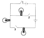
The diagram in Fig. shows a three-pin socket marked as 1, 2 and 3.

Identify and write live (L), neutral (N) and earth (E) against the correct number.
1→E,2→N,3→L
Topper's Solved these Questions
- HOUSEHOLD CIRCUITS BOOK - ICSECHAPTER - HOUSEHOLD CIRCUITS EXERCISE - EXERCISE -9(B) (MULTIPLE CHOICE TYPE)
2 Videos
- HOUSEHOLD CIRCUITS BOOK - ICSECHAPTER - HOUSEHOLD CIRCUITS EXERCISE - EXERCISE -9(A) (MULTIPLE CHOICE TYPE)
3 Videos
- FORCE BOOK - ICSECHAPTER - FORCE EXERCISE - EXERCISE 1( C) Multiple Choice questions
2 Videos
- MACHINESBOOK - ICSECHAPTER - MACHINESEXERCISE - EXERCISE-3(B) NUMERICALS
11 Videos
Similar Questions
Knowledge Check
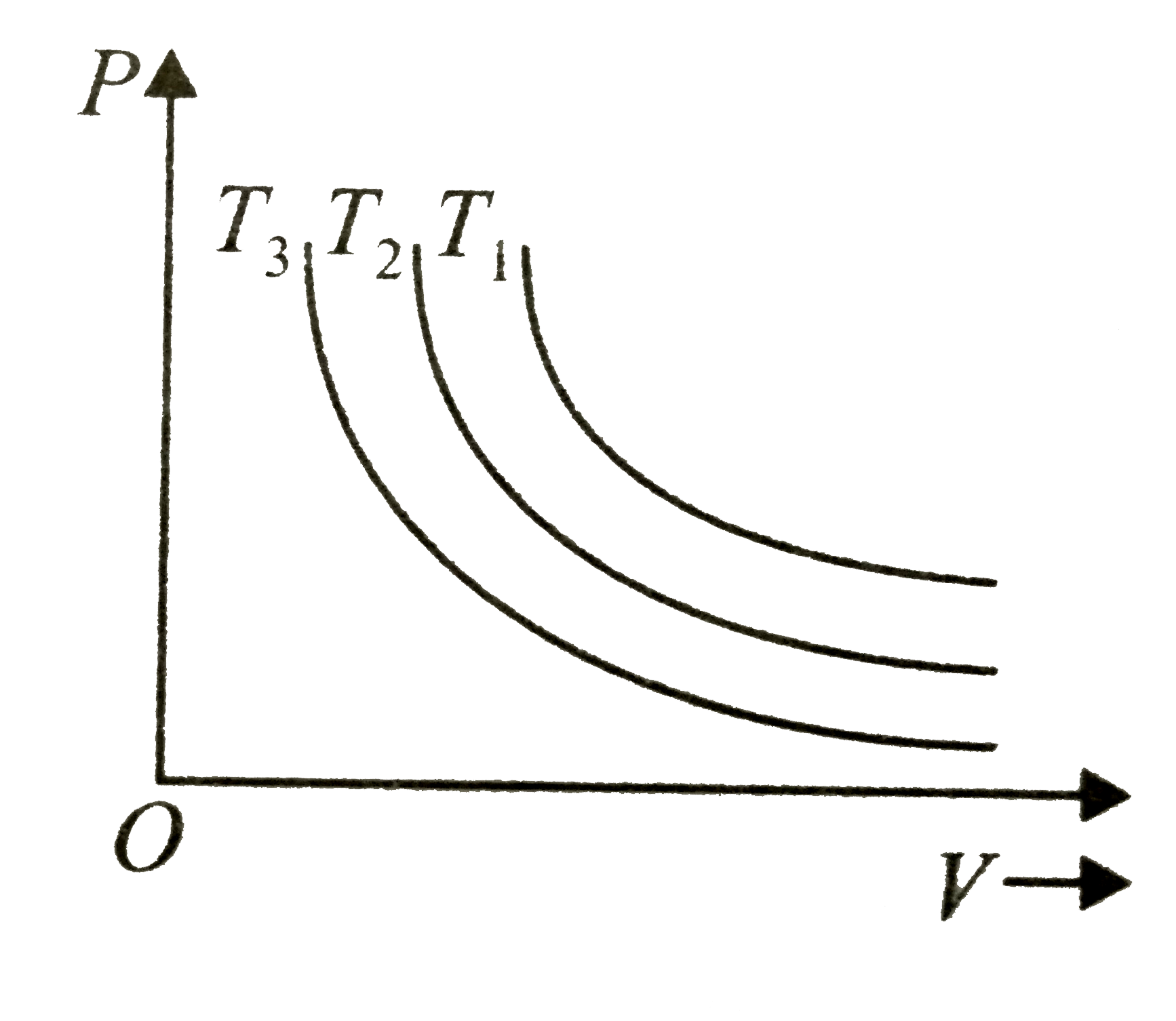
The isothermal diagram of a gas at three different temperatures T1,T2andT3, is show in the given figure .Then
 Aa.T1<T2<TBb. T1<T2>T3Cc.T1>T2>T3Dd.T1>T2<T3
The diagram in Fig. shows three lamps and three switches 1, 2 and 3 connected with two cells.
How are then the lamps connected : in series or in parallel ?

View SolutionThe diagram in Fig. shows three lamps and three switches 1, 2 and 3 connected with two cells.
Name the switch/switches to be closed so as to light all the three lamps.
View SolutionThe circuit diagram in Fig. shows three resistors 2Ω,4Ωand RΩ connected to a battery of e.m.f. 2 V and internal resistance 3 Ω. If current of 0.25 A flows through the circuit, find :
the p.d. across the R Ωor 2 Ω resistor,
View SolutionThe circuit diagram in Fig. shows three resistors 2Ω,4Ωand RΩ connected to a battery of e.m.f. 2 V and internal resistance 3 Ω. If current of 0.25 A flows through the circuit, find :
the p.d. across the 4 Ω resistor,
View SolutionThe circuit diagram in Fig. shows three resistors 2Ω,4Ωand RΩ connected to a battery of e.m.f. 2 V and internal resistance 3 Ω. If current of 0.25 A flows through the circuit, find :
the p.d. across the internal resistance of the cell,
View SolutionThe circuit diagram in Fig. shows three resistors 2Ω,4Ωand RΩ connected to a battery of e.m.f. 2 V and internal resistance 3 Ω. If current of 0.25 A flows through the circuit, find :
the value of R.
View Solution
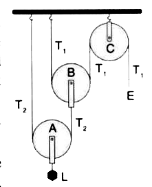
The diagram alongside shows an arrangement of three pulleys A,B and C. the load is marked as L and the effort as E.
(a) Name the pulleys A,B and C.
(b) Mark in the diagram the directions of load (L), effort (E) and tension T1andT2 in the two strings.
(c) How are the magnitudes of L and E related to the tension T1 ?
(d) Calculate mechanical advantage and velocity ratio of the arrangement.
(e) What assumptions have you made in parts (c) and (d) ?
View Solution


