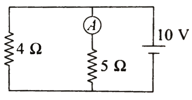
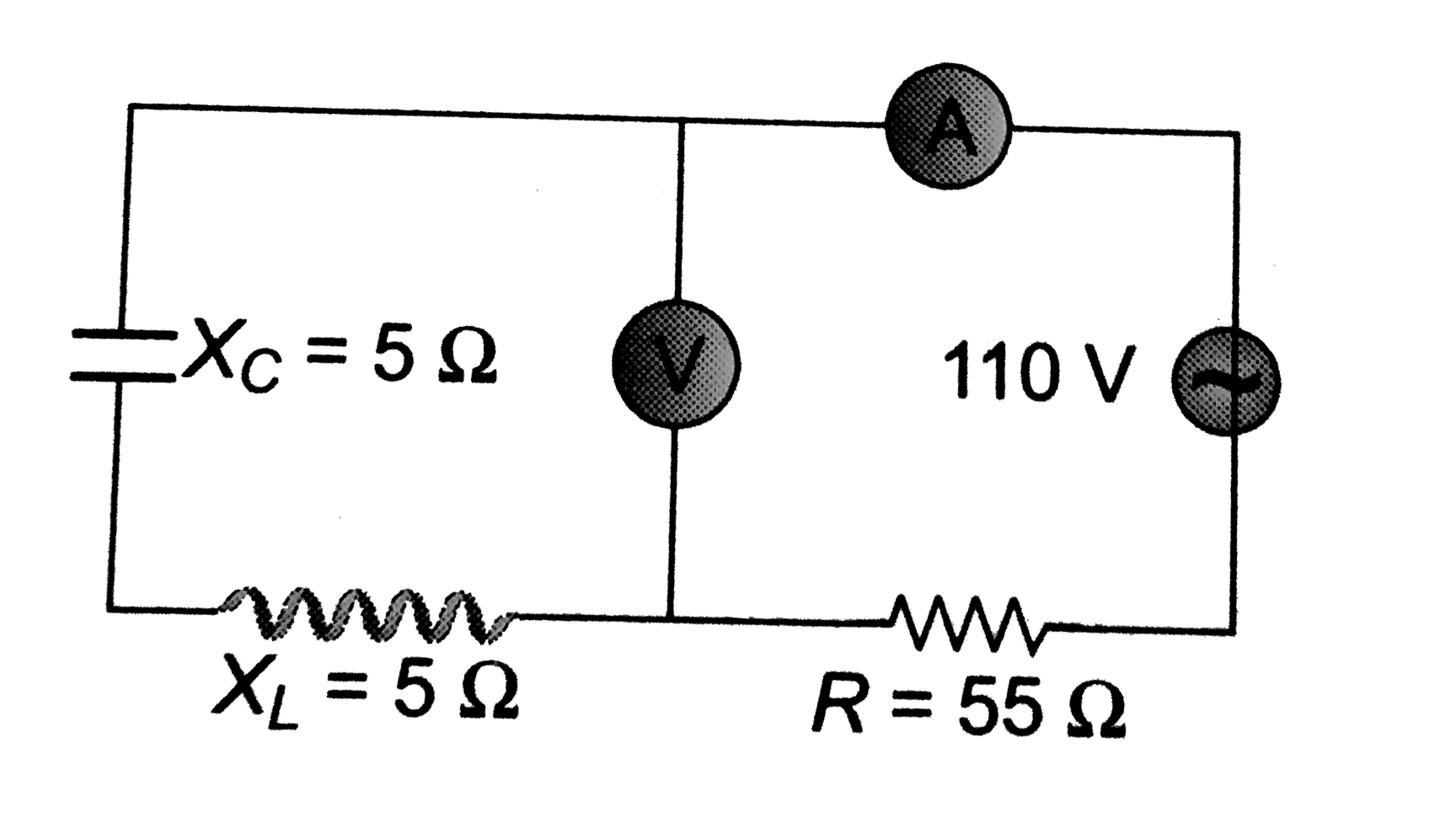
In the circuit shows in Fig. 6.41, the reading of the ammeter is (assume internal resistance of the battery be to zero)
4029A
109A
53A
2A
The correct Answer is:D
Voltage across 5Ω is 10V. Therefore,
I=105A=2A
Topper's Solved these Questions
- ELECTRICAL MEASURING INSTRUMENTSBOOK - CENGAGE PHYSICS ENGLISHCHAPTER - ELECTRICAL MEASURING INSTRUMENTSEXERCISE - Multiple Correct
7 Videos
- ELECTRICAL MEASURING INSTRUMENTSBOOK - CENGAGE PHYSICS ENGLISHCHAPTER - ELECTRICAL MEASURING INSTRUMENTSEXERCISE - Assertion-Reasoning
7 Videos
- ELECTRICAL MEASURING INSTRUMENTSBOOK - CENGAGE PHYSICS ENGLISHCHAPTER - ELECTRICAL MEASURING INSTRUMENTSEXERCISE - Subjective
18 Videos
- ELECTRIC POTENTIALBOOK - CENGAGE PHYSICS ENGLISHCHAPTER - ELECTRIC POTENTIALEXERCISE - DPP 3.5
15 Videos
- ELECTROMAGNETIC INDUCTIONBOOK - CENGAGE PHYSICS ENGLISHCHAPTER - ELECTROMAGNETIC INDUCTIONEXERCISE - compression type
7 Videos
Similar Questions
In the circuit shown in figure, reading of ammeter will
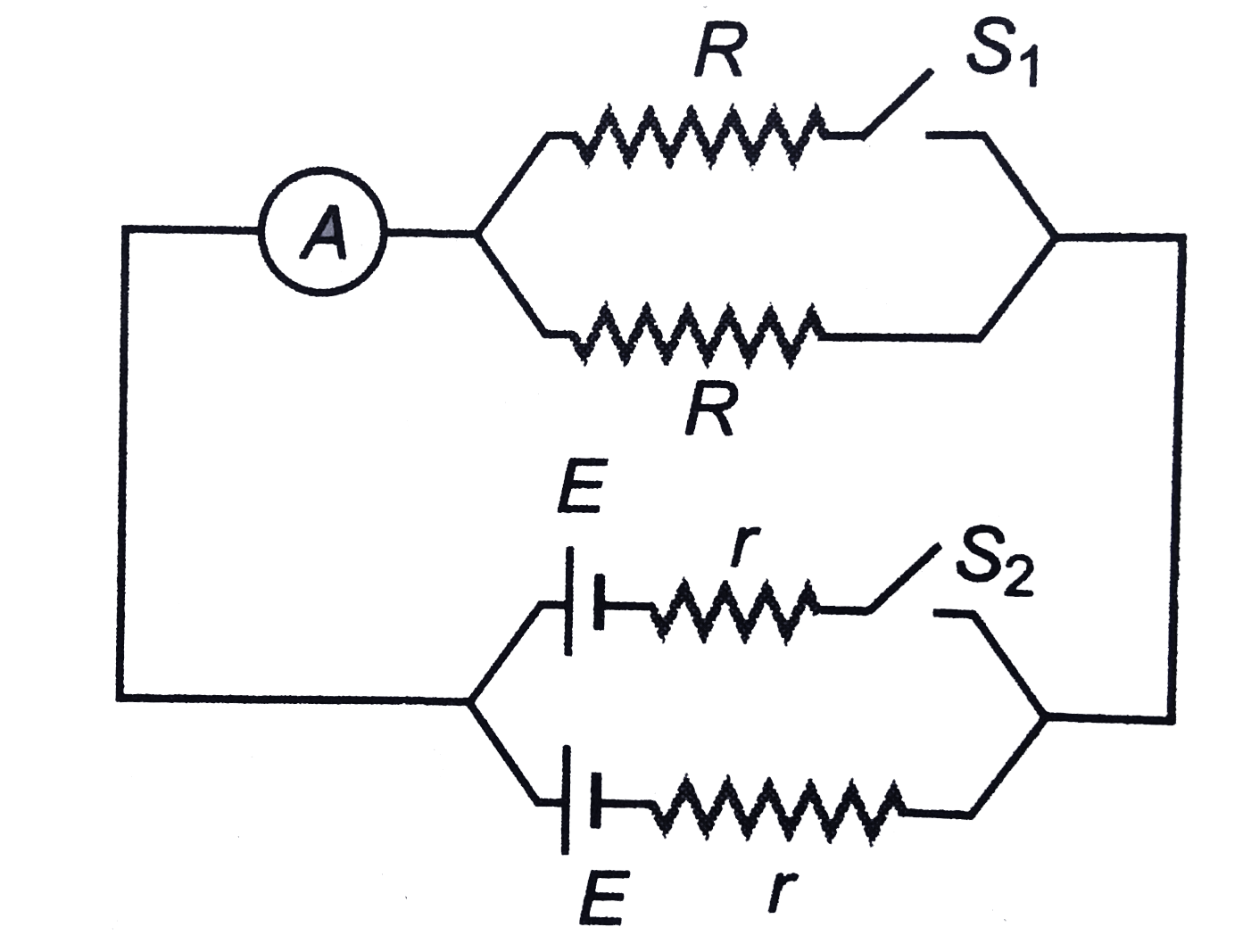
View SolutionThe reading of the ammeter in the circuit below is
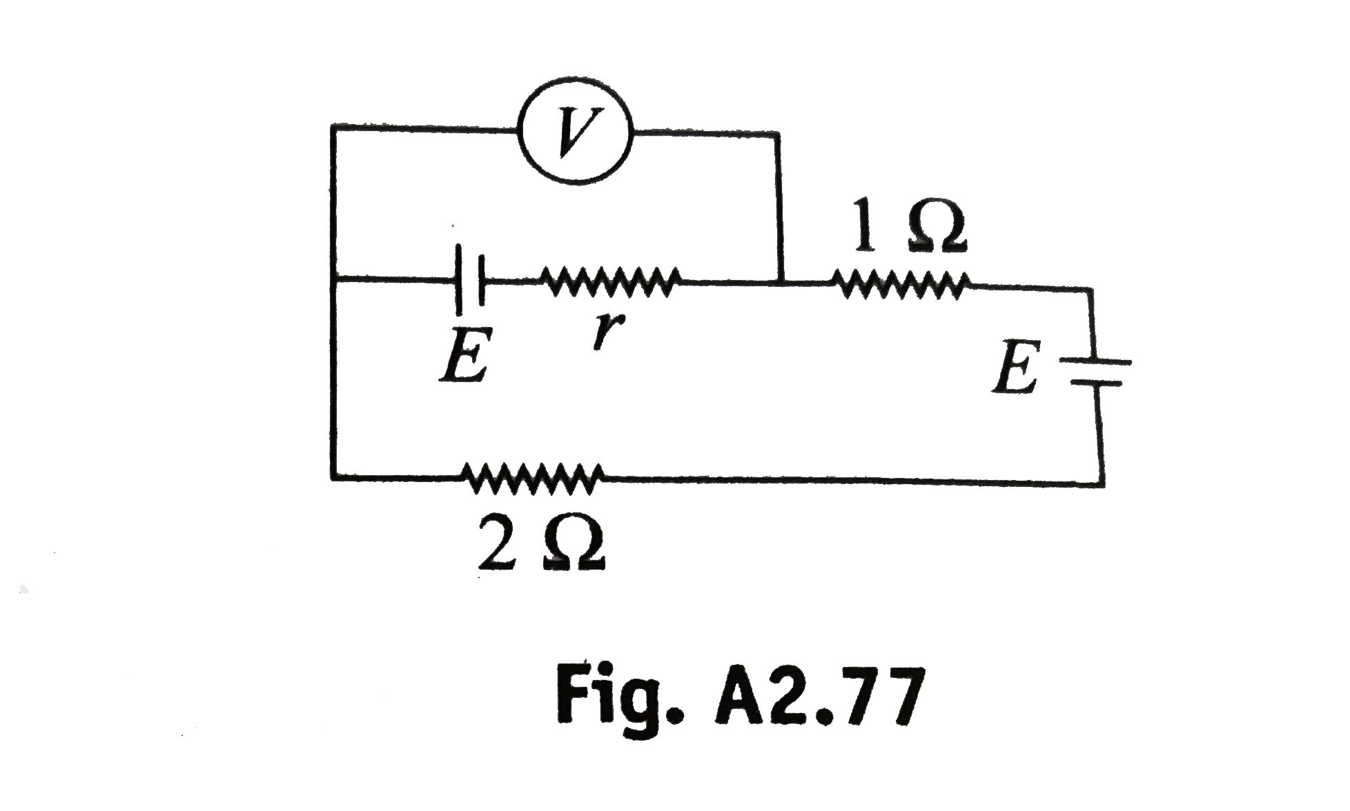
View SolutionIn the given circuit, the reading of ideal voltmeter is E/2. The internal resistance of the battery is
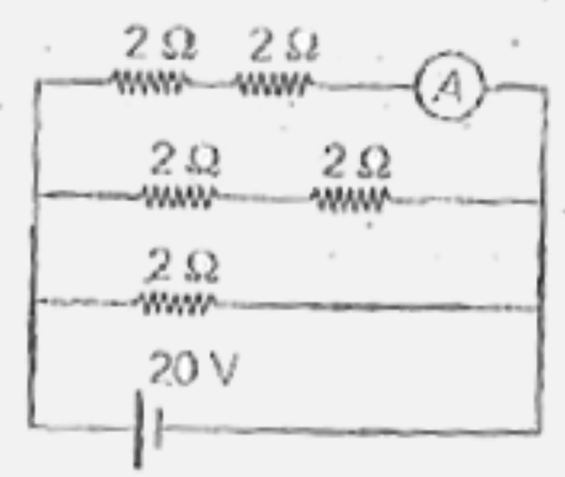
View SolutionThe reading of ammeter in the circuit is
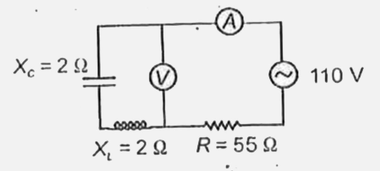
View SolutionThe reading of the ideal ammeter in the circuit is
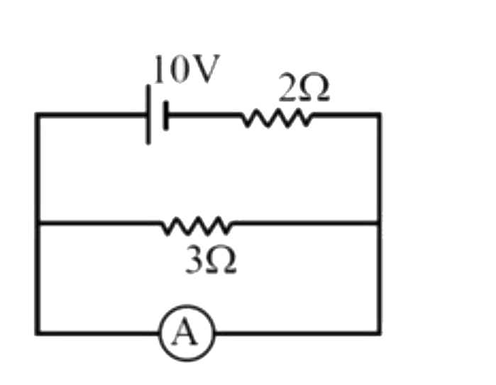
View SolutionThe reading of the ideal ammeter will be (Resistance of ideal ammeters is zero)
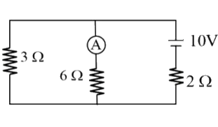
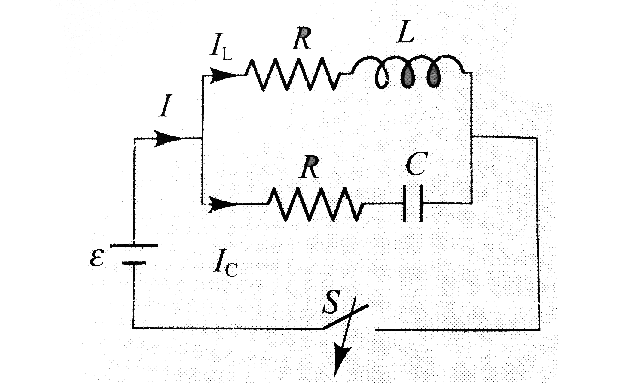
View SolutionIn the circuit shows in Fig. the battery has negligible internal resistance. Show that the current in the circuit through the battery rises instanlty to its steady state value E/R when the switch is closed, provided that resistance R is √L/C.
View SolutionIn the circuit shown in figure the reading of ammeter is the same with both switches open as with both closed. Then find the resistance R. (ammeter is ideal).
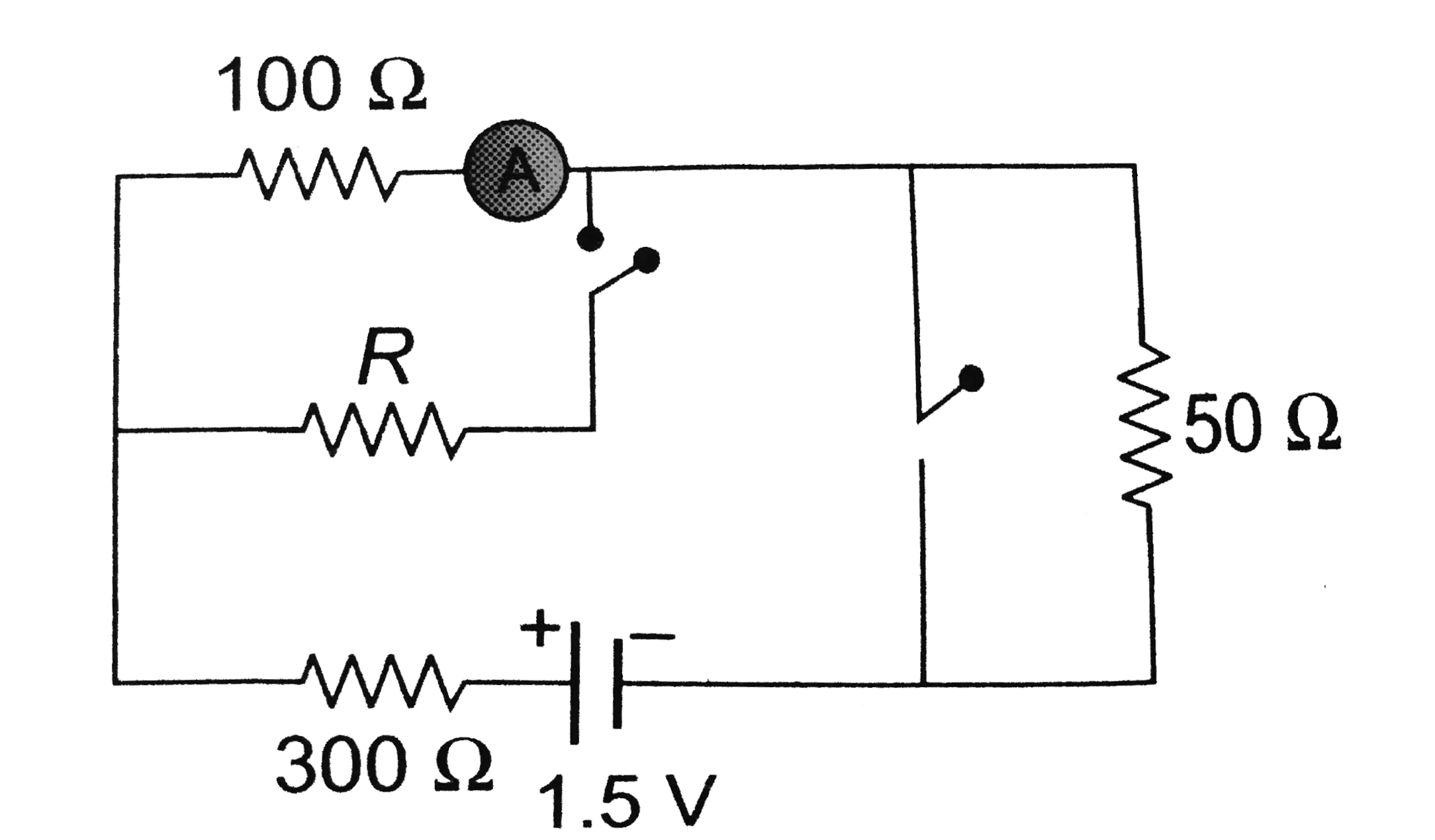
View SolutionIn the circuit shown in figure the reading of ammeter is the same with both switches open as with both closed. Then find the resistance R. (ammeter is ideal).

View SolutionThe reading of ammeter in the circuit shown will be
View Solution
