A metallic shell has a point charge 'q' kept inisde its cavity. Which one of the following diagrams correctly represents the electric lines of forces?
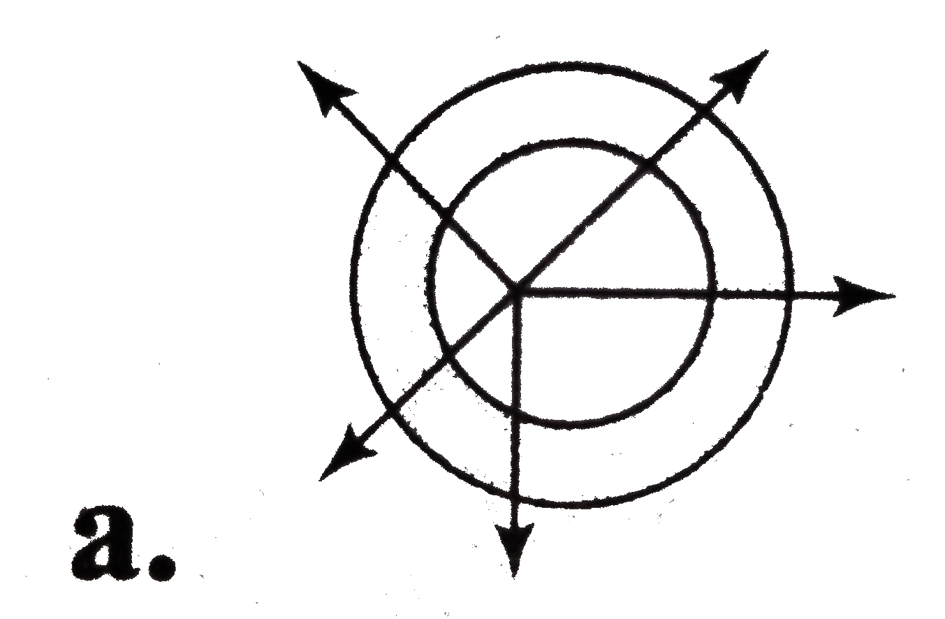
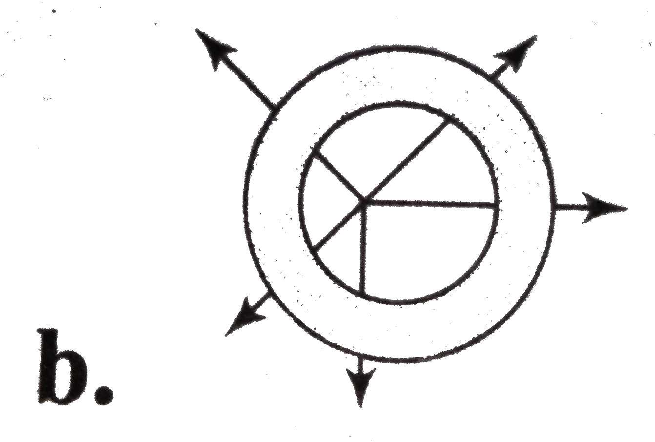
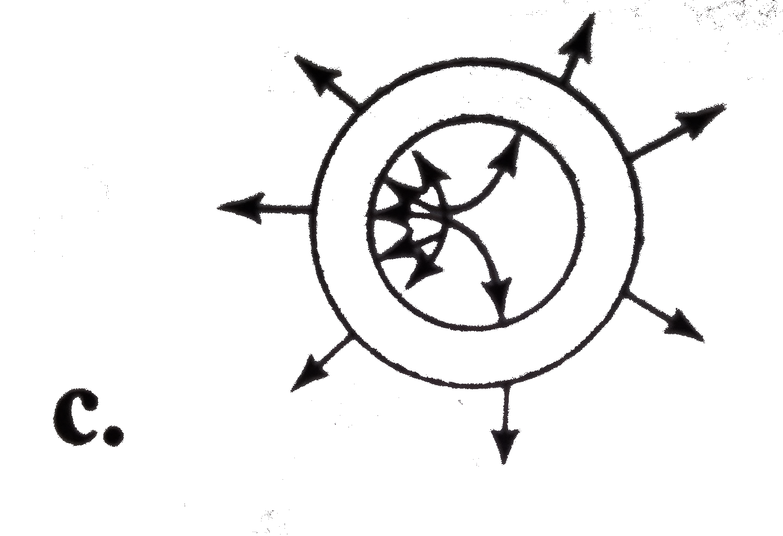
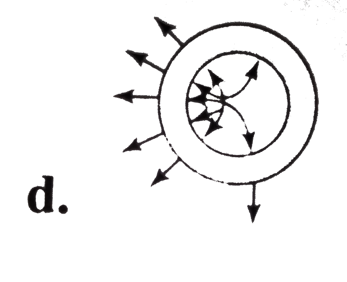
The correct Answer is:C
To solve the problem regarding the representation of electric lines of force around a metallic shell with a point charge 'q' inside its cavity, we can follow these steps:
1. Understanding the Setup:
- We have a metallic shell with a cavity.
- Inside this cavity, there is a point charge 'q'.
2. Behavior of Electric Field in Conductors:
- In electrostatic equilibrium, the electric field inside a conductor is zero.
- Therefore, the electric field inside the metallic shell (the conductor part) will be zero.
3. Effect of the Point Charge:
- The point charge 'q' will create an electric field in the space inside the cavity.
- This electric field will radiate outward from the point charge.
4. Induced Charges on the Shell:
- The presence of the charge 'q' will induce a charge on the inner surface of the metallic shell.
- If 'q' is positive, negative charge will be induced on the inner surface of the shell, while an equal amount of positive charge will be induced on the outer surface of the shell.
5. Electric Field Lines:
- The electric field lines will start from the point charge 'q' and will be directed outward.
- Inside the cavity, the lines will be radial and will point away from the charge.
- Upon reaching the inner surface of the shell, the electric field lines will be perpendicular to the surface of the shell.
6. Outside the Shell:
- The electric field outside the shell will behave as if all the charge were concentrated at the center of the shell. The field lines will be radial and directed outward from the shell.
7. Choosing the Correct Diagram:
- The correct diagram must show:
- Radial lines emanating from the point charge 'q' inside the cavity.
- Lines that are perpendicular to the inner surface of the shell.
- The outer surface of the shell showing electric field lines that are also radial.
Conclusion:
After analyzing the behavior of electric fields around a metallic shell with a point charge inside, we can conclude that the correct representation of electric lines of force is the one that shows radial lines from the charge and perpendicular lines at the surface of the shell.
- We have a metallic shell with a cavity.
- Inside this cavity, there is a point charge 'q'.
- In electrostatic equilibrium, the electric field inside a conductor is zero.
- Therefore, the electric field inside the metallic shell (the conductor part) will be zero.
- The point charge 'q' will create an electric field in the space inside the cavity.
- This electric field will radiate outward from the point charge.
- The presence of the charge 'q' will induce a charge on the inner surface of the metallic shell.
- If 'q' is positive, negative charge will be induced on the inner surface of the shell, while an equal amount of positive charge will be induced on the outer surface of the shell.
- The electric field lines will start from the point charge 'q' and will be directed outward.
- Inside the cavity, the lines will be radial and will point away from the charge.
- Upon reaching the inner surface of the shell, the electric field lines will be perpendicular to the surface of the shell.
- The electric field outside the shell will behave as if all the charge were concentrated at the center of the shell. The field lines will be radial and directed outward from the shell.
- The correct diagram must show:
- Radial lines emanating from the point charge 'q' inside the cavity.
- Lines that are perpendicular to the inner surface of the shell.
- The outer surface of the shell showing electric field lines that are also radial.
After analyzing the behavior of electric fields around a metallic shell with a point charge inside, we can conclude that the correct representation of electric lines of force is the one that shows radial lines from the charge and perpendicular lines at the surface of the shell.
Topper's Solved these Questions
- COULOMB LAW AND ELECTRIC FIELDBOOK - CENGAGE PHYSICS ENGLISHCHAPTER - COULOMB LAW AND ELECTRIC FIELDEXERCISE - Multiple Correct
8 Videos
- COULOMB LAW AND ELECTRIC FIELDBOOK - CENGAGE PHYSICS ENGLISHCHAPTER - COULOMB LAW AND ELECTRIC FIELDEXERCISE - Comprehension
25 Videos
- COULOMB LAW AND ELECTRIC FIELDBOOK - CENGAGE PHYSICS ENGLISHCHAPTER - COULOMB LAW AND ELECTRIC FIELDEXERCISE - Subjective
32 Videos
- CENGAGE PHYSICS DPPBOOK - CENGAGE PHYSICS ENGLISHCHAPTER - CENGAGE PHYSICS DPPEXERCISE - subjective type
51 Videos
- ELECTRIC CURRENT & CIRCUITSBOOK - CENGAGE PHYSICS ENGLISHCHAPTER - ELECTRIC CURRENT & CIRCUITSEXERCISE - Kirchhoff s law and simple circuits
15 Videos
Similar Questions
Knowledge Check
A spherical insulator of radius R is charged uniformly with a charge Q throughout its volume and contains a point charge Q16 located at its centre. Which of the following graphs best represents qualitatively, the variation of electric field intensity E with distance r from the centre?
A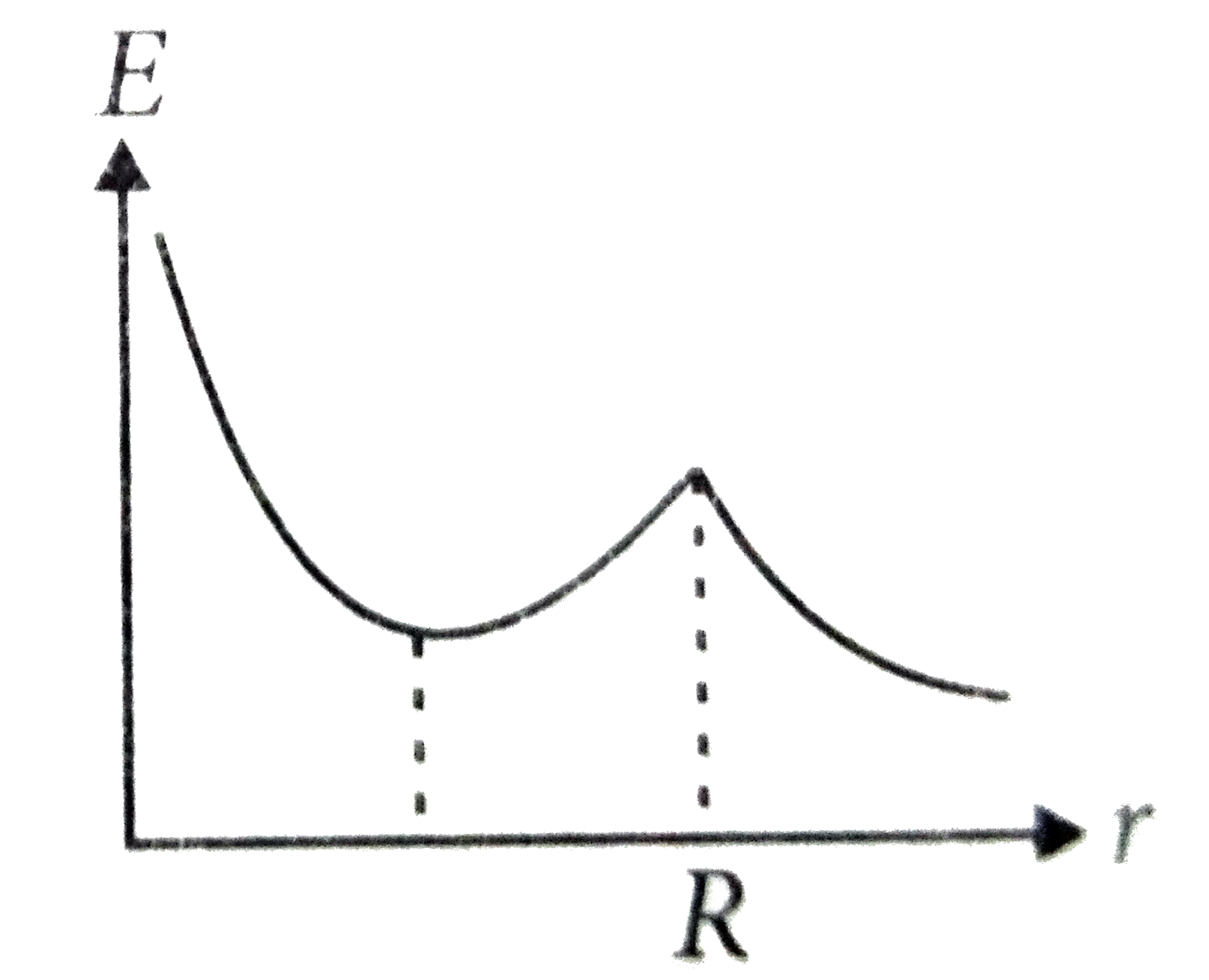 B
B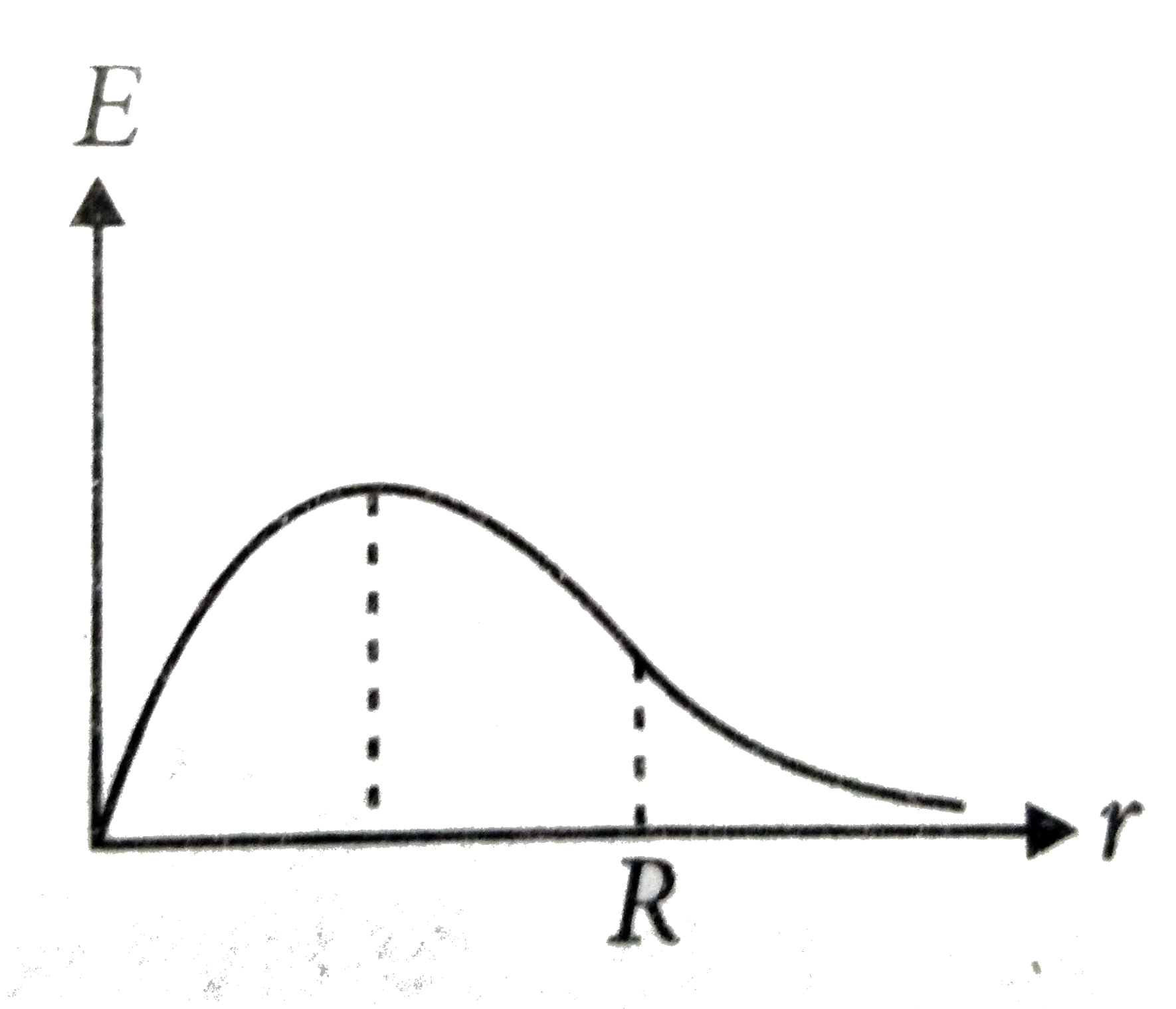 C
C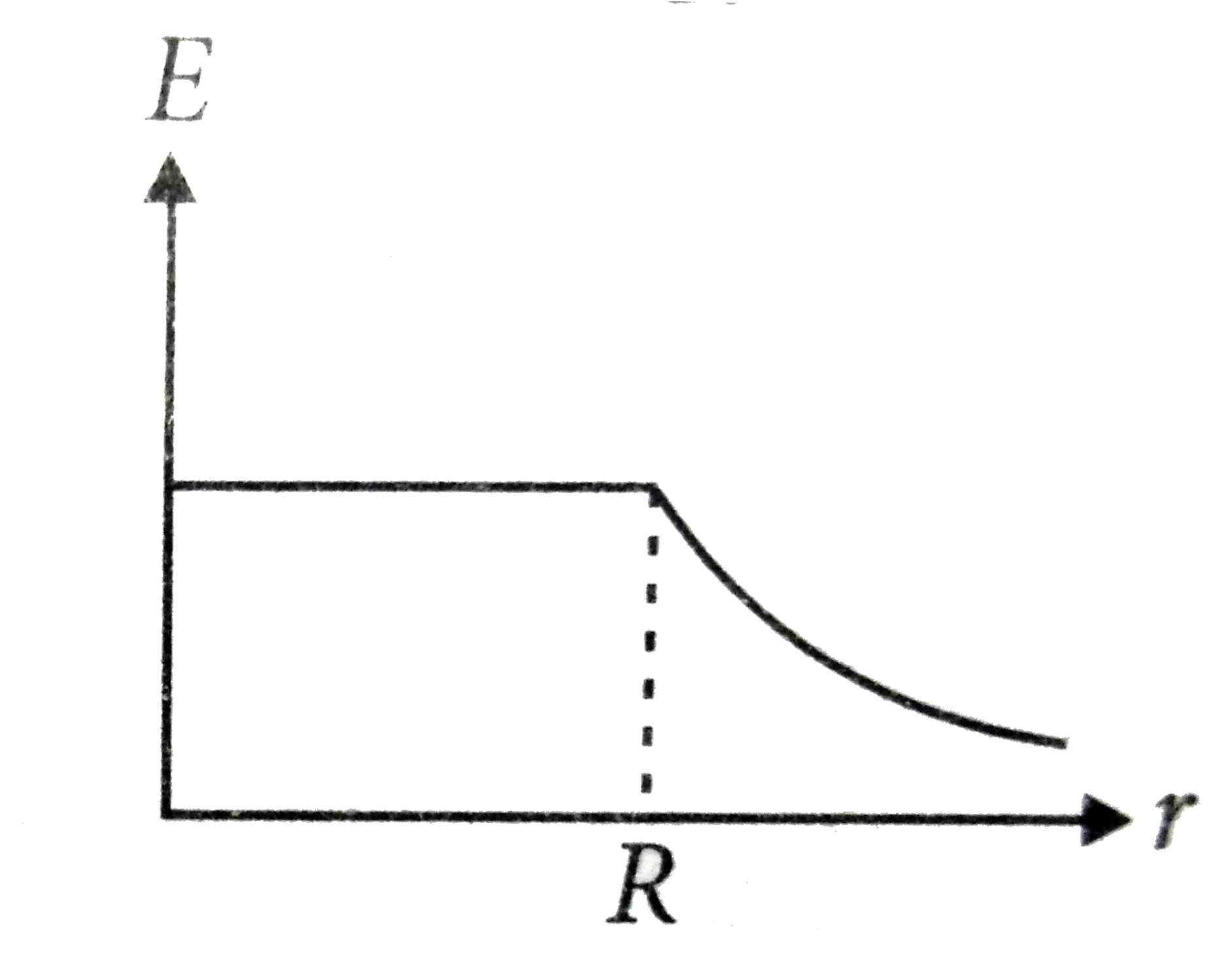 D
D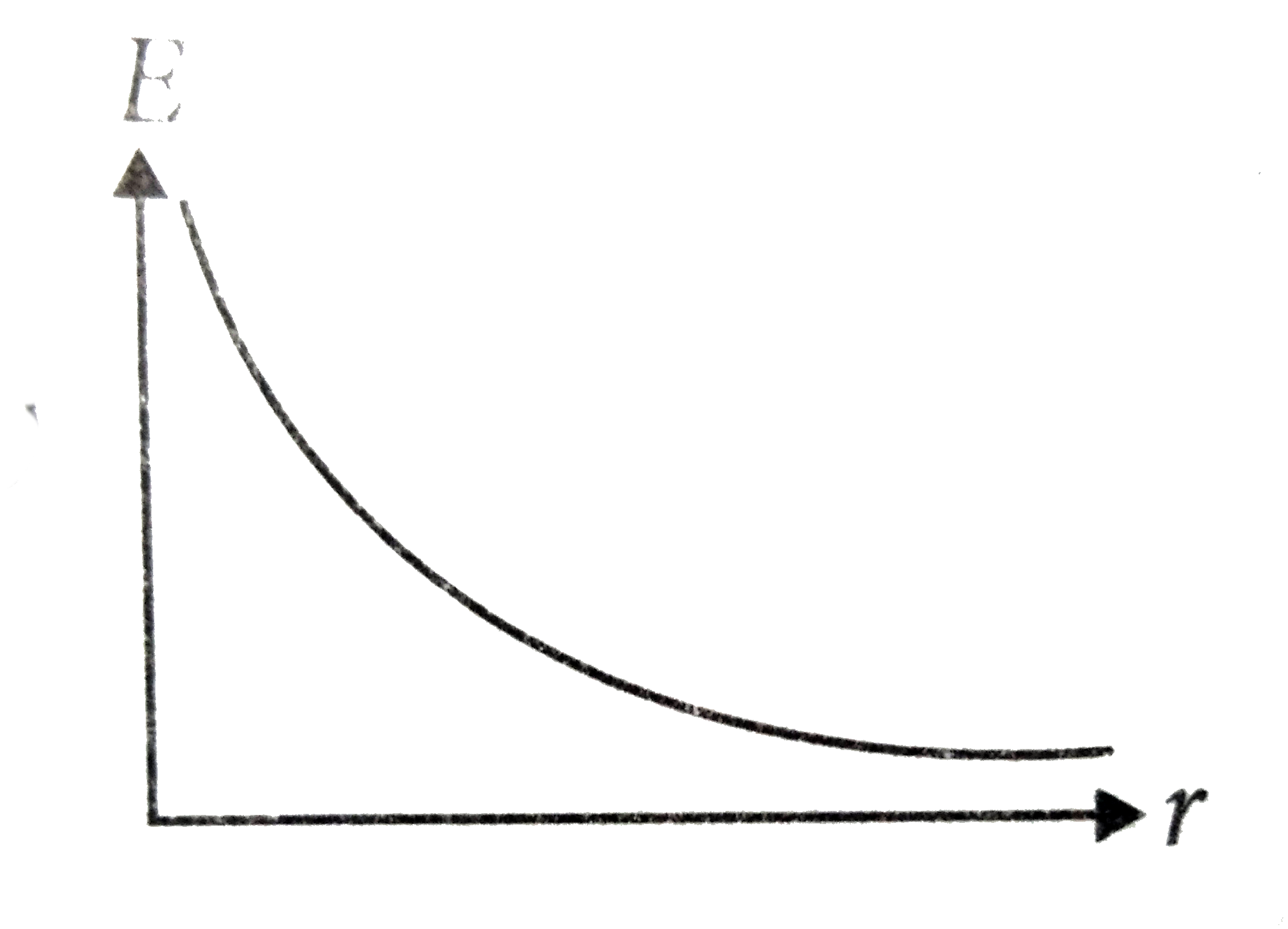
Which one of the following correctly represents an organism and its ecological niche?
View SolutionA thin spherical shell of radius R has charge Q spread uniformly over its surface. Which of the following graphs most closely represents the electric field E(r) produced by the shell in the range 0≤r<∞, where r is the distance from the centre of the shell?
View SolutionA thin spherical shell of radius R has charge Q spread uniformly over its surface. Which of the following graphs most closely represents the electric field E(r) produced by the shell in the range 0≤r<∞, where r is the distance from the centre of the shell?
View SolutionWhich one of the following pattern of electric line of force can't possible:
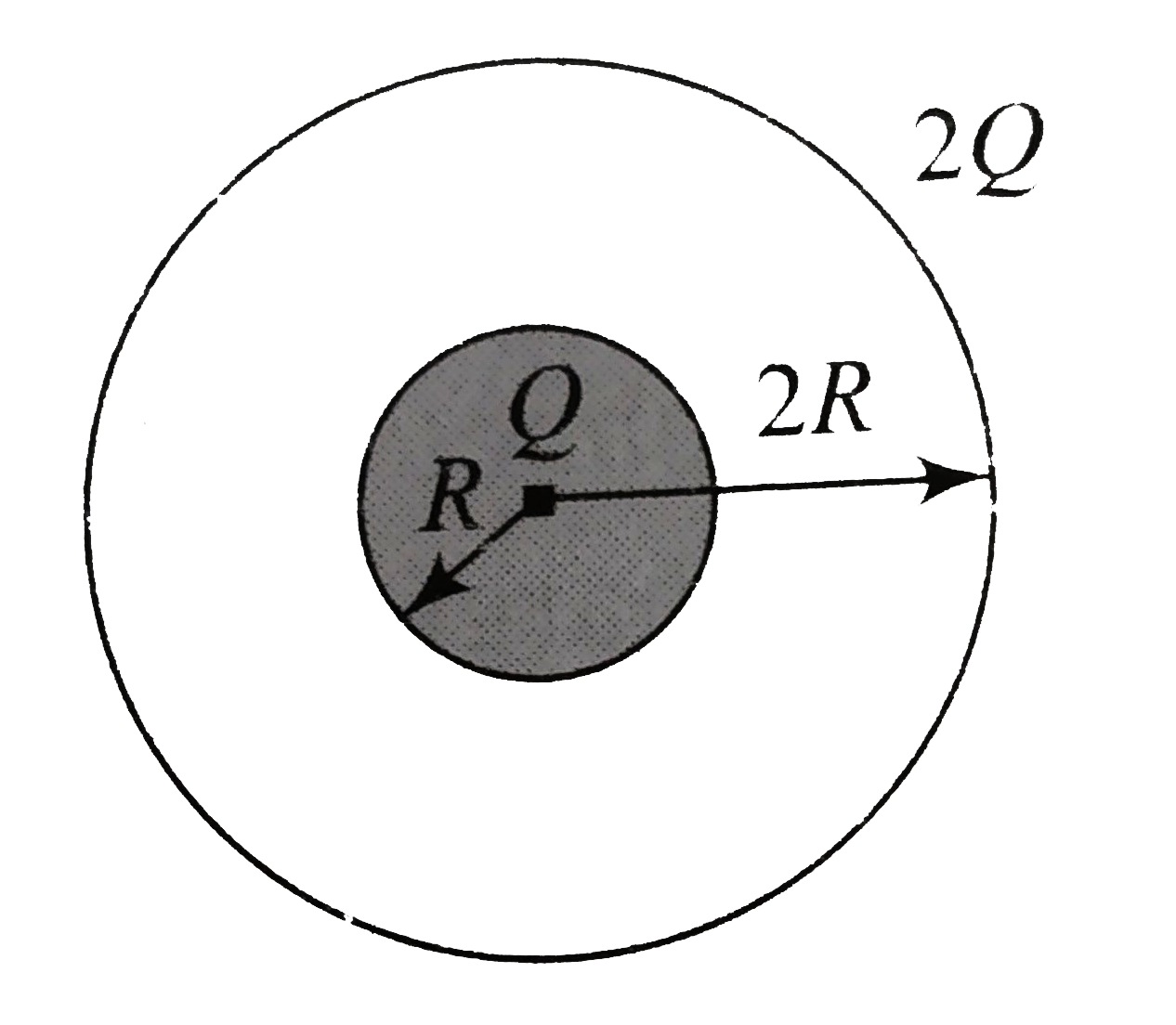
View SolutionA charge Q is uniformly distributed in a dielectric sphere of radius R (having dielectric constant unity). This dielectric sphere is enclosed by a concentric spherical shell of radius 2R and having uniformly distributed charge 2Q. Which of the following graph correctly represents variation of electric field with distance r from the common centre?
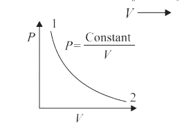
View SolutionFor the diagram given for an ideal gas, out of the following which one correctly represent the diagram?
View SolutionThe diagram shows the electric field lines produced by an electrostalic focusing device.
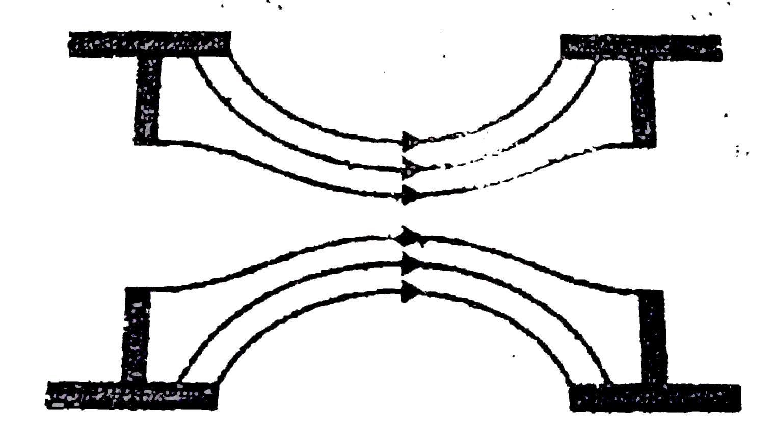
Which one of the following diagrams best shows the corresponding equipotential lines? The electric field are shown as broken lines on each of the diagrams.
View Solution
