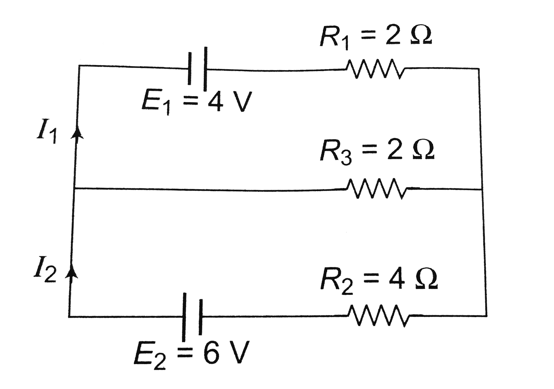
निम्न दिये गये परिपथ में तथा है तो धारा होगी

1.6A
1.8A
1.25A
1.0A
The correct Answer is:B
चित्र में दर्शाये गये लूप (1) व (2) में किरचॉफ नियम लगाने पर लूप (1) में

लूप (2) में
समीकरण (i) व (ii) को हल करने पर,
Topper's Solved these Questions
- धारा विद्युतBOOK - ERRORLESS HINDICHAPTER - धारा विद्युतEXERCISE - Graphical Questions (Objective Questions)
8 Videos
- धारा विद्युतBOOK - ERRORLESS HINDICHAPTER - धारा विद्युतEXERCISE - JEE SECTION (More than one correct answer)
4 Videos
- धारा विद्युतBOOK - ERRORLESS HINDICHAPTER - धारा विद्युतEXERCISE - Ordinary Thinking Objective Questions (विभिन्न मापन यंत्र)
123 Videos
- धारा का चुम्बकीय प्रभाव BOOK - ERRORLESS HINDICHAPTER - धारा का चुम्बकीय प्रभाव EXERCISE - धारा का चुम्बकीय प्रभाव
23 Videos
- ध्वनि एवं तरंगBOOK - ERRORLESS HINDICHAPTER - ध्वनि एवं तरंगEXERCISE - SELF EVALUATION TEST
19 Videos
Similar Questions
निम्न में से कौन-सा ग्राफ ओह्मीय प्रतिरोध है
View Solutionचित्र में दिखाये गये परिपथ के लिए

View Solutionकिसी परिपथ में 30 V की बैटरी 40.8 ओम का एक प्रतिरोध तथा एक एमीटर सभी श्रेणीक्रम में जुड़े हर हैं। यदि एमीटर की कुंडली का प्रतिरोध 480 ओम है और इससे जुड़े संट का प्रतिरोध 20 ओम है, एमीटर का पाठ्यांक होगा।
View Solutionएक 10 m लम्बा सीधा एवं क्षैतिज तार पूर्व-पश्चिम दिशा के अनुदिश है। जो मुक्त रूप से पृथ्वी के चुम्बकीय क्षेत्र के क्षैतिज घटक के लंबवत् 5.0 m/s के वेग से गिरता है। पृथ्वी के चुम्बकीय क्षेत्र का क्षैतिज घटक 0.30×10⁻⁴Wbm2 है। तार में पश्चिम से पूर्व की ओर प्रेरित विभव प्रवणता का तात्क्षणिक मान होगा
View Solutionएक इंजन नियत चाल से वृतीय पथ पर गतिमान है। यदि इंजन सिटी बजाकर 500Hz आवृत्ति की ध्वनि उतपन्न करता हे। तो चित्र में दिखाए अनुसार पथ के केन्द्र पर खड़ा हुआ एक व्यक्ति है द्वारा प्रेक्षित आवृत्ति होगी

View SolutionIn the circuit shows in Fig E=15V, R1=1Ω, R2=1Ω, R3=2Ω, and L=1.5H. The currents flowing through R1,R2,and R3 are i1,i2, and i3, respectively.
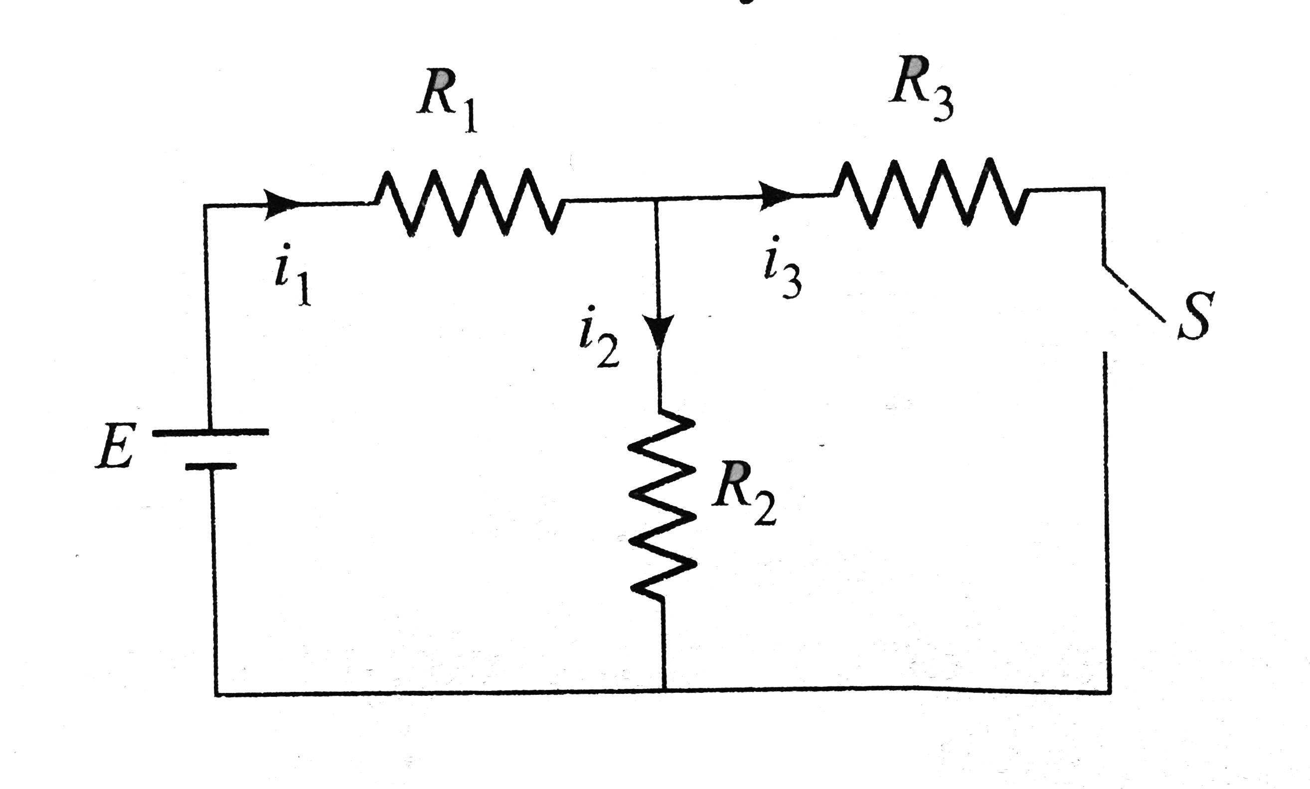
Immediately after tuning switch S on,
View SolutionIn the circuit shows in Fig E=15V, R1=1Ω, R2=1Ω, R3=2Ω, and L=1.5H. The currents flowing through R1,R2,and R3 are i1,i2, and i3, respectively.
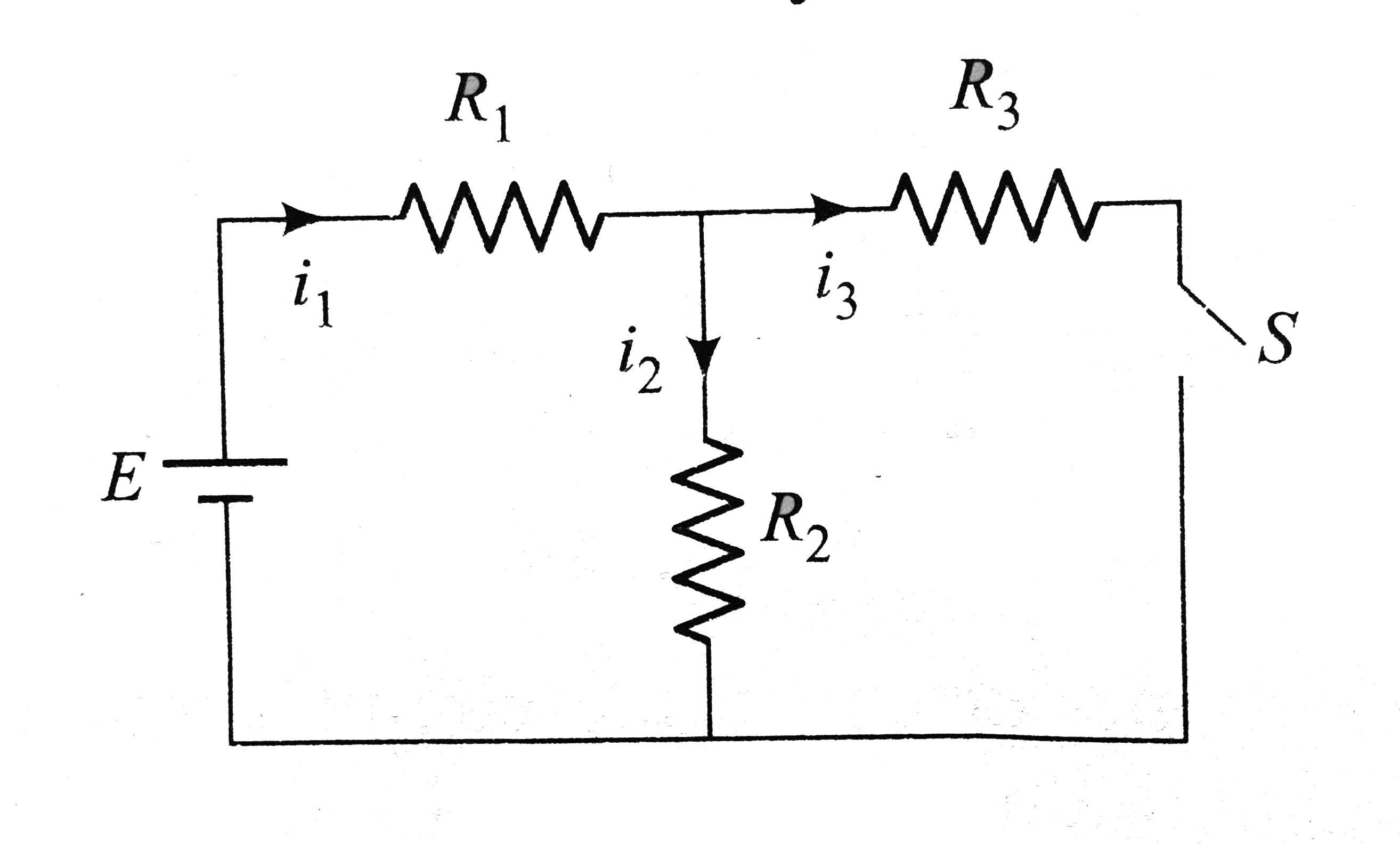
After the circuit reaches the steady state,
View SolutionIn the circuit shows in Fig E=15V, R1=1Ω, R2=1Ω, R3=2Ω, and L=1.5H. The currents flowing through R1,R2,and R3 are i1,i2, and i3, respectively.
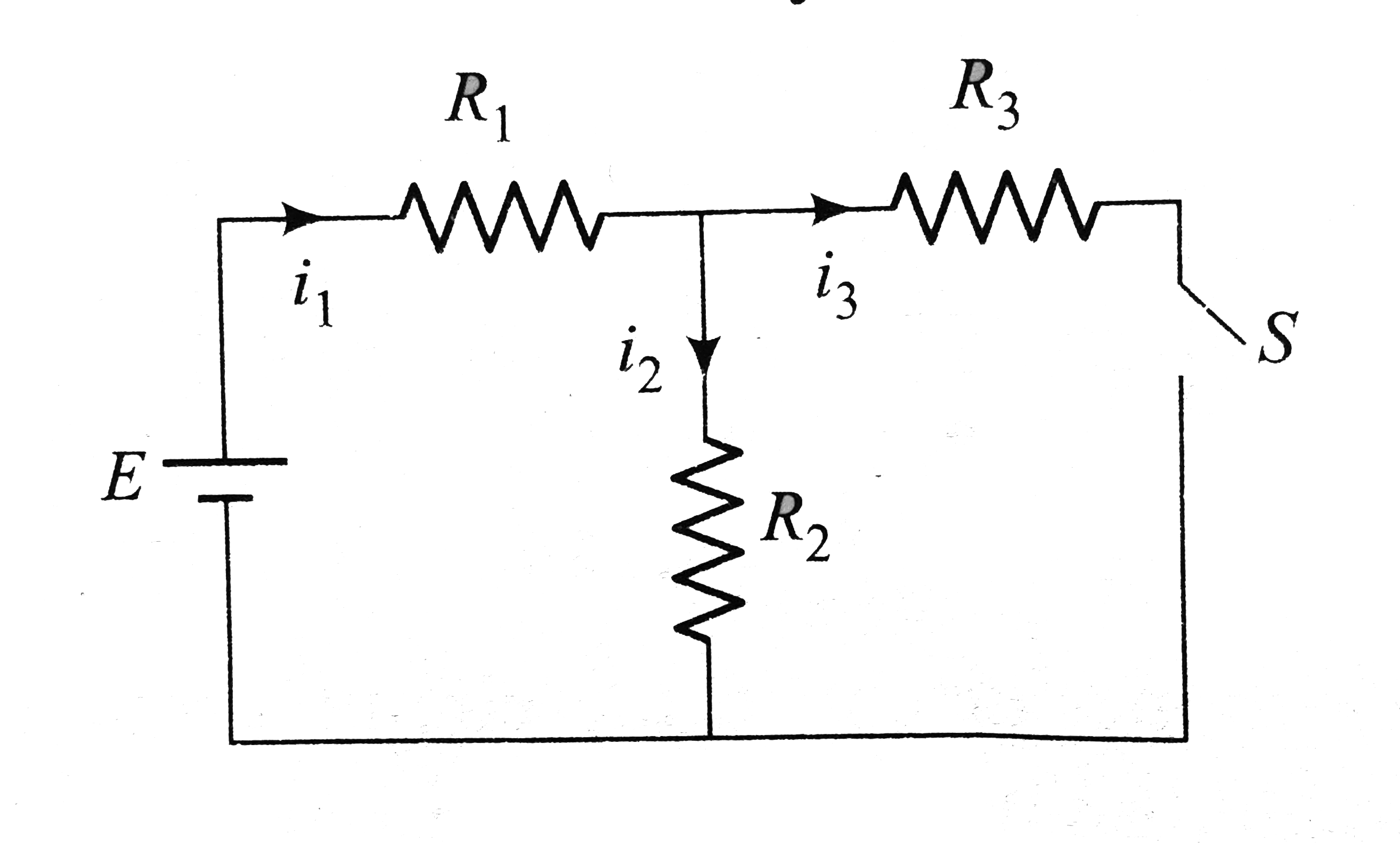
Immediately after connecting switch S,
View SolutionIn the network shown the potential difference between A and B is (R = r_(1) = r_(2) = r_(3) = 1 Omega, E_(1) = 3V, E_(2) = 2V, E_(3) = 1V )
View SolutionIn the circuit shown below E1=4.0V,R1=2Ω,E2=6.0V,R2=4Ω and R3=2Ω. The current I1 is
View Solution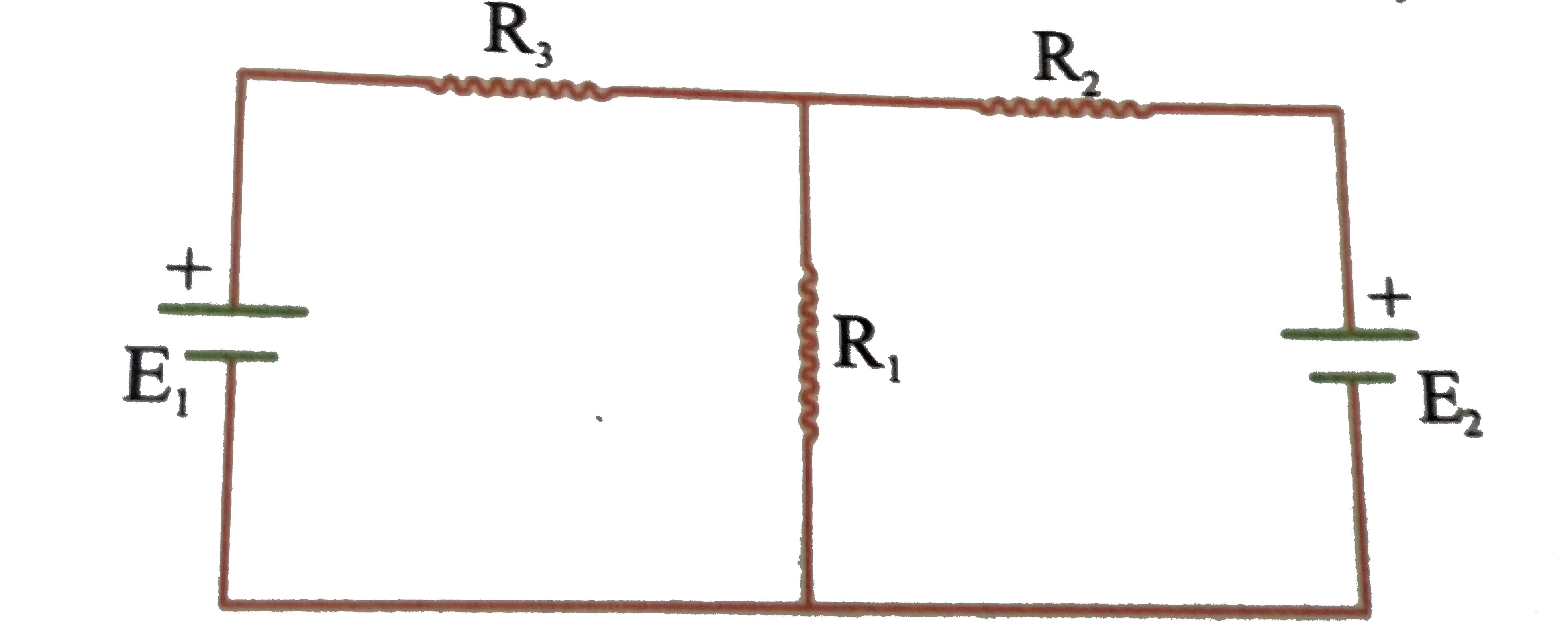
In the electrical network, shown in the diagram R1=5Ω,R2=2Ω,R3=3Ω and E1=2E2=10V, sources have negligible internal resistance. For this network,
View SolutionIf E_(1) , E_(2),E_(3) ... E_(n) represent emfs of a number of cells of internal resistances r_(1) , r_(2) , ... r_(n) then mention their equivalent emf and internal resistance when these are connected in series.
View SolutionIn the given circuit. E_(1) = 6 volts, E_(2) = 2 volts, E_(3) = 6 volts R_(1) = 6OmegaR_( 2)=2Omega R_(3) = 4Oemga, R_(4) = 3Omega and C=5muF . Find the current in R_(3) and energy stored in the capacitor at steady state
View SolutionIn the circuit shown, E_(1)= 7 V, E_(2) = 7 V, R_(1) = R_(2) = 1Omega and R_(3) = 3 Omega respectively. The current through the resistance R_(3)
View SolutionIn the circuit shown below, E_(1)=17V,E_(2)=21V,R_(1)=2Omega,R_(2)=3Omega and R_(3)=5Omega . Using Kirchhoff.s laws, find the currents flowing through the resistors R_(1),R_(2) and R_(3) . (Internal resistance of each of the batteries is negligible.)
View SolutionIn the circuit shows in Fig E=15V, R1=1Ω, R2=1Ω, R3=2Ω, and L=1.5H. The currents flowing through R1,R2,and R3 are i1,i2, and i3, respectively.

Immediately after tuning switch S on,
View Solution
