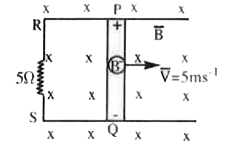
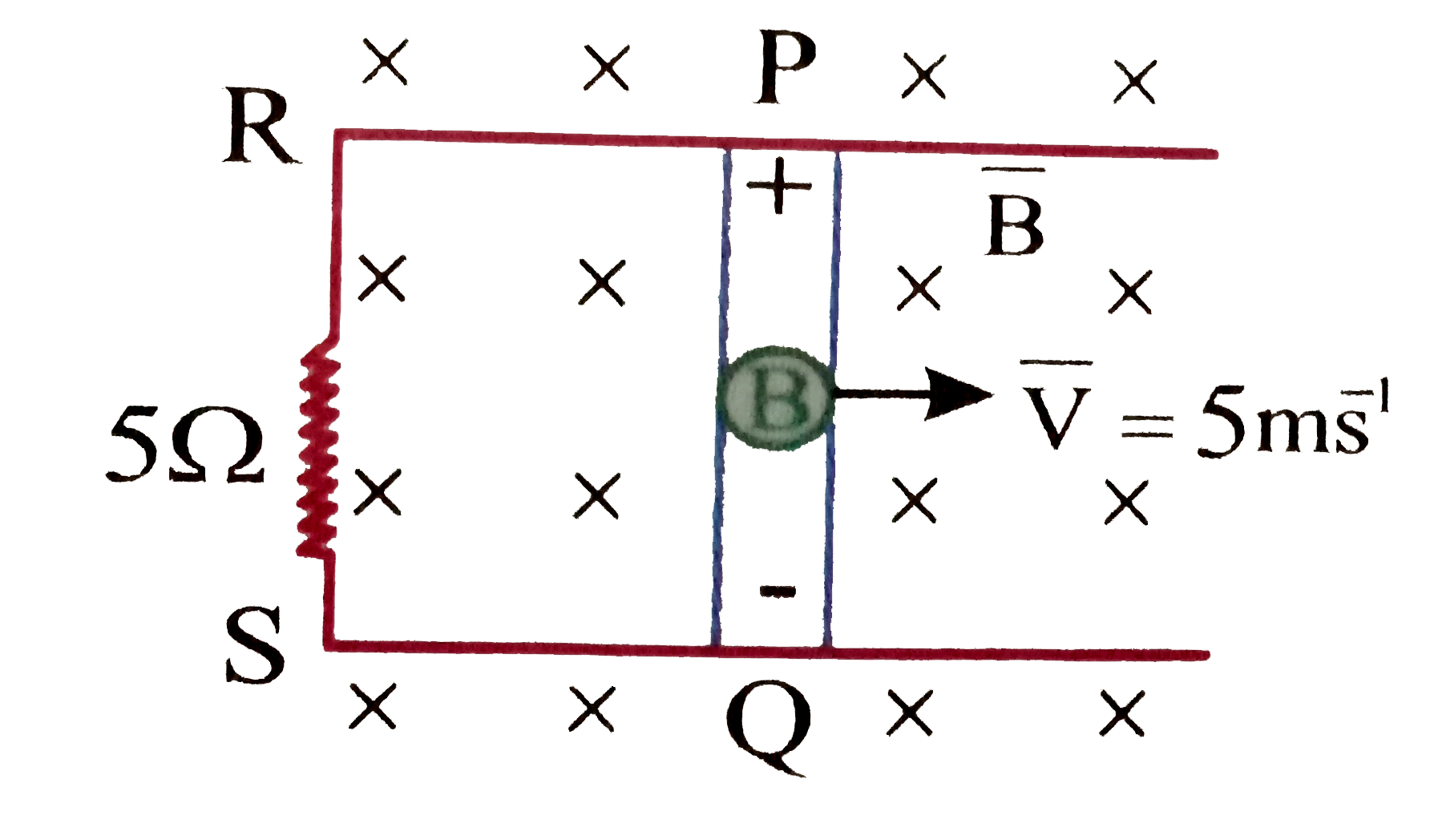
Figure shows a conducting rod PQ in contact with metal rails RP and SQ, which are 0.25m apart in a uniform magnetic field of flux density 0.4T acting perpendicular to the plane of the paper. Ends R and S are connected through a resistance. What is the emf when the rod moves to the right with a velocity of ? What is the magnitude and direction of the current through the resistance? If the rod PQ moves to the left with the same speed, what will be the new current and its direction?
 Solution in Telugu
Current ,
As the rod .PQ. moves to right as shown, the free electrons in it experience a Lorentz force. According to F.L.H., the force is towards the end .Q. of rod. They move from P to Q, hence the end of the rod P becomes deficient of electrons
Applying Fleming.s right hand rule, the current in the rod shall flow from Q to P.
(b): If the rod PQ moves to the left with the same speed, then the current of 0.1 A will flow in the rod PQ from P to Q
Topper's Solved these Questions
- ELECTROMAGNETIC INDUCTIONBOOK - AAKASH SERIESCHAPTER - ELECTROMAGNETIC INDUCTIONEXERCISE - EXERCISE-IA
33 Videos
- ELECTROMAGNETIC INDUCTIONBOOK - AAKASH SERIESCHAPTER - ELECTROMAGNETIC INDUCTIONEXERCISE - EXERCISE-IB
18 Videos
- ELECTRIC FIELD AND POTENTIALBOOK - AAKASH SERIESCHAPTER - ELECTRIC FIELD AND POTENTIALEXERCISE - PROBLEMS (LEVEL-II)
32 Videos
- ELECTROMAGNETIC WAVESBOOK - AAKASH SERIESCHAPTER - ELECTROMAGNETIC WAVESEXERCISE - EXERCISE -II
20 Videos
Similar Questions
A cylindrical bar magnet is kept along the axis of a circular coil. If the magnet is rotated along its axis, then
View Solution(A): Total induced emf in a loop is not confined to any particular point but it is distributed around the loop.
(R): In general when there is no change in magnetic flux, no induced emf is produced
View SolutionA metal sphere with its centre at A and radius R has a charge 2q on it. The field at a point B outside the sphere is E. If another metal sphere of radius 3R and having a charge -3q is placed with its centre at point B, find out the resultant electric field at a point mid way between A and B.
View SolutionA parallel plate capacitor consists of two circular plates each of radius 2cm, separated by a distance of 0.1mm. If the potential difference across the plates is varying at the rate of 5×10⁶Vs−1, then the value of displacement current is
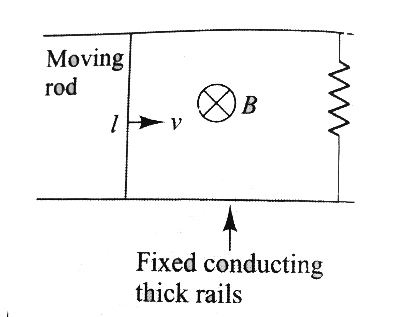
View SolutionShows a rod of length l and resistance r moving on two rails shorted by a resistance R . A uniform magnetic field B is present normal to the plane of rod and rails. Show the electrical equivalence of each branch.
View SolutionFigure shows a conducting rod PQ in contact with metal rails RP and SQ, which are 0.25m apart in a uniform magnetic field of flux density 0.4T acting perpendicular to the plane of the paper. Ends R and S are connected through a 5Ω resistance. What is the emf when the rod moves to the right with a velocity of 5ms−1 ? What is the magnitude and direction of the current through the 5Ω resistance? If the rod PQ moves to the left with the same speed, what will be the new current and its direction?

View SolutionA conducting rod of unit length moves with a velocity of 5m/s in a direction perpendicular to its length and perpendicular to a uniform magnetic field of magnitude 0.4T . Find the emf induced between the ends of the stick.
View SolutionFollowing figure shows a metal rod PQ resting on the smooth ralls AH and positioned between the poles of a permanent magnet. The rails, the rod and the magnetic field are in three mutual perpendicular directions. A galvanometer G connects the rails through a switch K. Length of the rod 15 cm, B 0.50 T, resistance of the closed loop containing the rod 9.0 mOmega . Assume the field to be uniform. Suppose K is open and the rod is moved with a speed of 12"cm s"^(-1) in the direction shown. Give the polarity and magnitude of the induced emf.
View SolutionFollowing figure shows a metal rod PQ resting on the smooth ralls AH and positioned between the poles of a permanent magnet. The rails, the rod and the magnetic field are in three mutual perpendicular directions. A galvanometer G connects the rails through a switch K. Length of the rod 15 cm, B 0.50 T, resistance of the closed loop containing the rod 9.0mΩ. Assume the field to be uniform.
What is the induced emf in the moving rod if the magnetic field is parallel to the rails instead of being perpendicular?
View SolutionA metal rod PQ is resting on the rails A'B' and positioned between the poles of a permanent magnet. The rails, the rod and the magnetic field are in three mutually perpendicular directions. A galvanometer G connects the rails through a switch K. Length of the rod = 15 cm, B = 0.50 T, resistance of the closed loop containing the rod = 9.0 mOmega . Assume the field to be uniform. Suppose K is open and the rod is moved with a speed of 12 cm. s^(-1) in the direction shown. Give the polarity and magnitude of the induced emf.
View SolutionA conducting rod of unit length moves with a velocity of 5m/s in a direction perpendicular to its length and perpendicular to a uniform magnetic field of magnitude 0.4T . Find the emf induced between the ends of the stick.
View SolutionFigure 1 below shows a metallic rod MN of length l= 80cm, kept in a uniform magnetic field of flux density B= 0.5T, on two parallel metallic rails P and Q. Calculate the emf that will be induced between its two ends, when it is moved towards right with a constant velocity v of 36km/hr
View SolutionShows a rod of length l and resistance r moving on two rails shorted by a resistance R . A uniform magnetic field B is present normal to the plane of rod and rails. Show the electrical equivalence of each branch.
View SolutionShows a rod of length l and resistance r moving on two rails shorted by a resistance R. A uniform magnetic field B is present normal to the plane of rod and rails. Show the electrical equivalence of each branch.

View SolutionA conducting rod of length is moved at constant velocity v_(0) on two parallel, conducting, smooth, fixed rails, that are placed in a uniform constant magnetic field B perpendicular to the plane for the rails as shown in Fig. A resistance R is connected between the two ends of the rails. Then which of the following is/are correct:
View Solution
