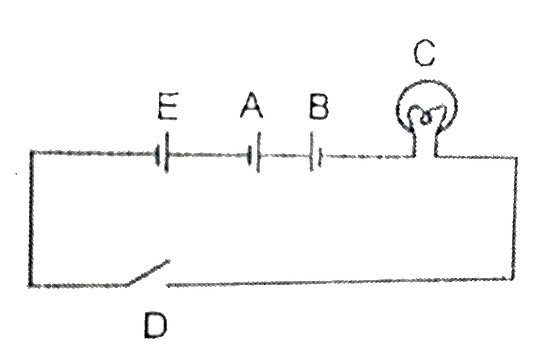
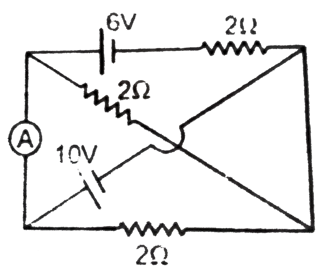
Represent the connections shown below by a circuit diagram.
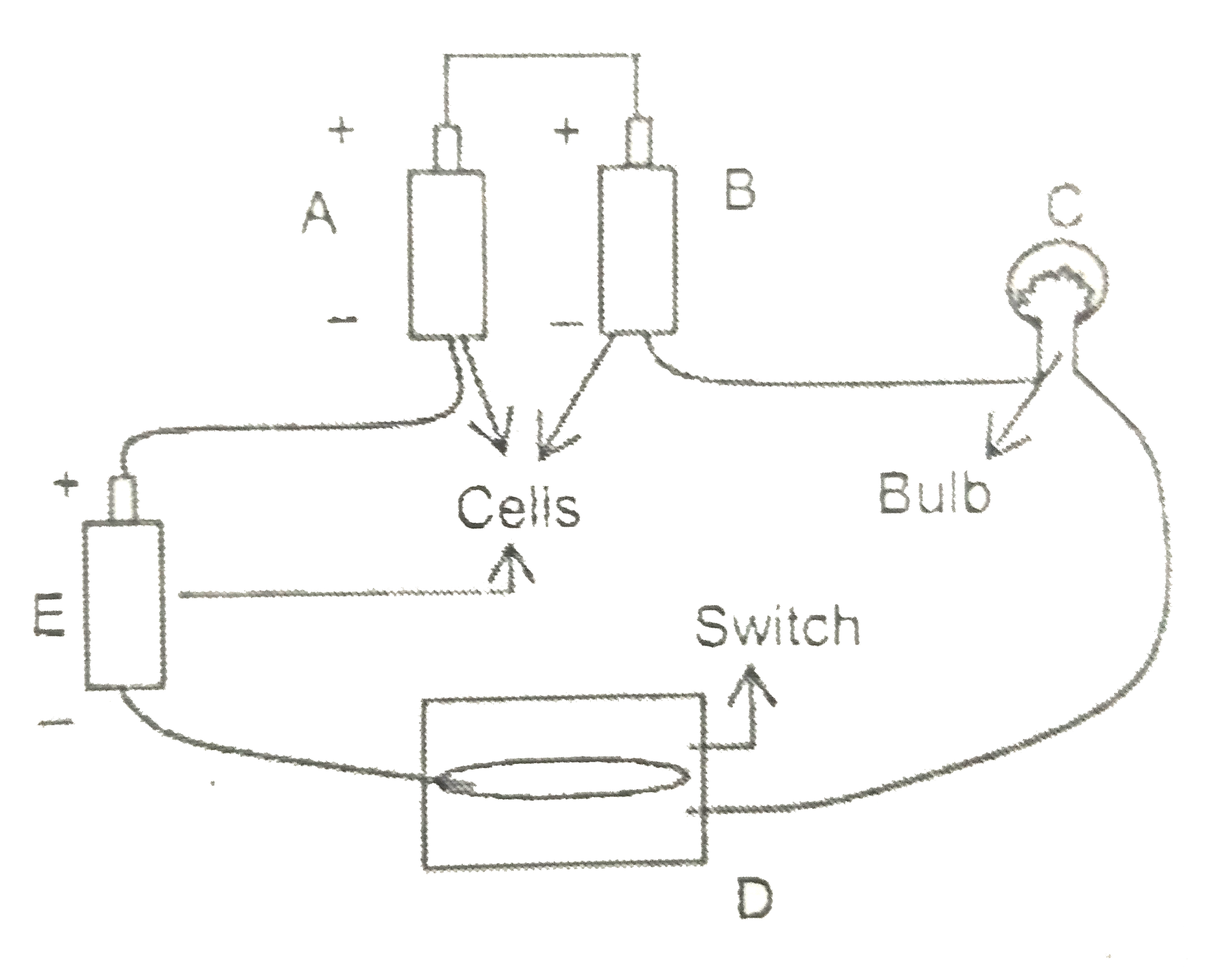
Video Solution
Text Solution
|
Topper's Solved these Questions
- ElectricityBOOK - PEARSON IIT JEE FOUNDATIONCHAPTER - ElectricityEXERCISE - Level - III
20 Videos
- ElectricityBOOK - PEARSON IIT JEE FOUNDATIONCHAPTER - ElectricityEXERCISE - Test 2
30 Videos
- ElectricityBOOK - PEARSON IIT JEE FOUNDATIONCHAPTER - ElectricityEXERCISE - Level - I
86 Videos
- HEAT BOOK - PEARSON IIT JEE FOUNDATIONCHAPTER - HEAT EXERCISE - Test 2
14 Videos
Similar Questions
(a) With the help of a circuit diagram, obtain the relation for the equivalent resistance of two resistances connected in parallel.
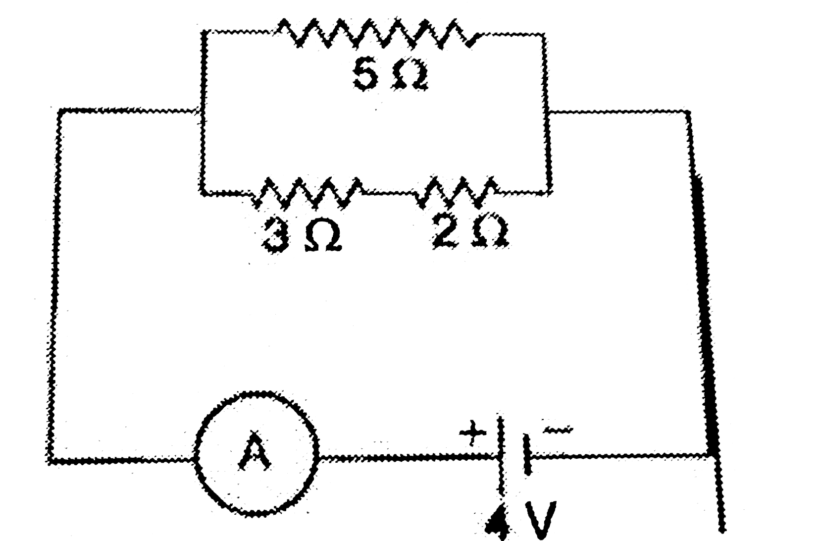
(b) In the circuit diagram shown below, find:
(i) Total resistance.
(ii) Current shown by the ammeter A
View SolutionWhich two circuit components are connected in parallel in the following circuit diagram ?

View Solution
Knowledge Check
A circuit is shown below.
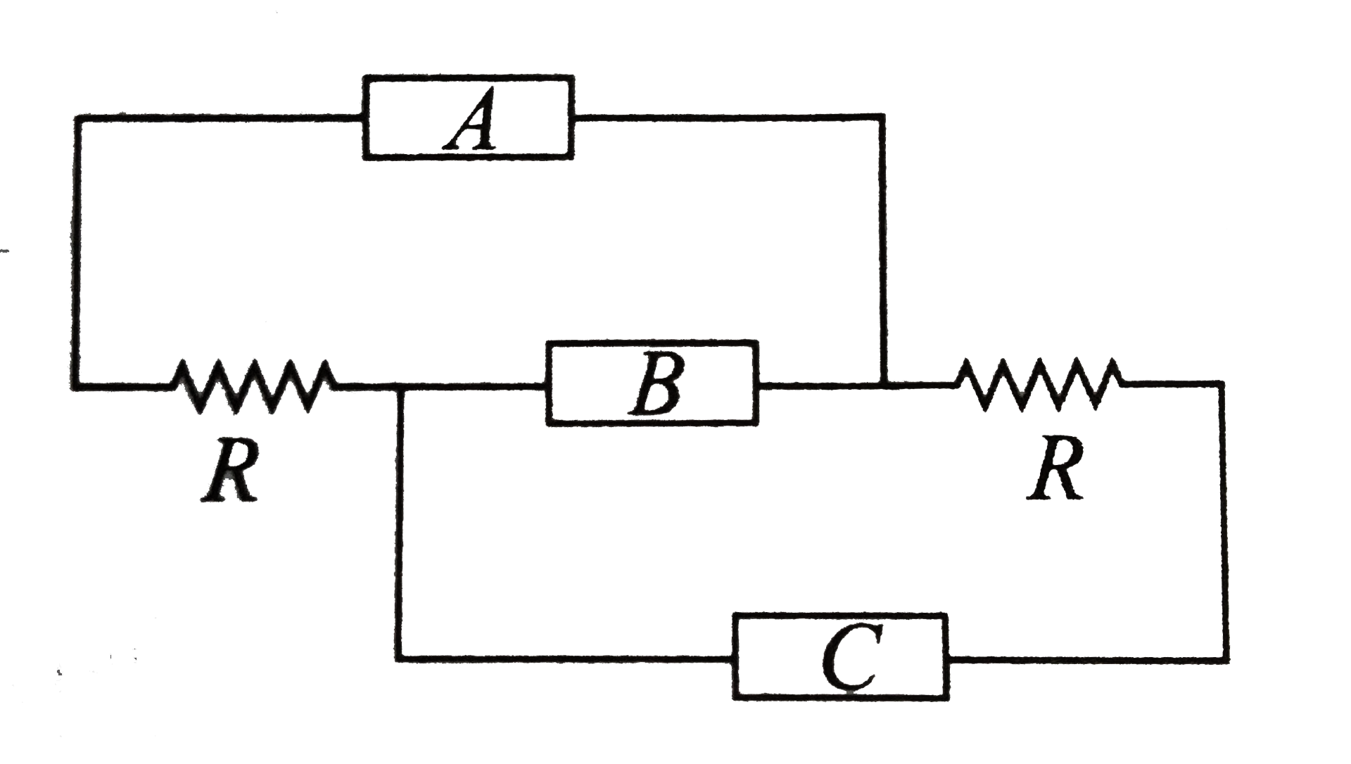 AIf A is an ideal ammeter, B an ideal battery of voltage V, and C an ideal voltmeter, the ratio reading of C/ reading of A is R.BIf A is a capacitor, B an ideal ammeter and C an ideal battery of voltage V, the potential difference across the capacitor is zero.CIf A is an ideal ammeter, B an ideal battery of voltage of V, and C an ideal voltmeter, the ratio reading of C/reading of A isR/2DIf A is a capacitor, B an ideal ammeter, and C an ideal battery of voltage V, the potential difference across the capacitor is 2 V.
In the circuit diagram shown
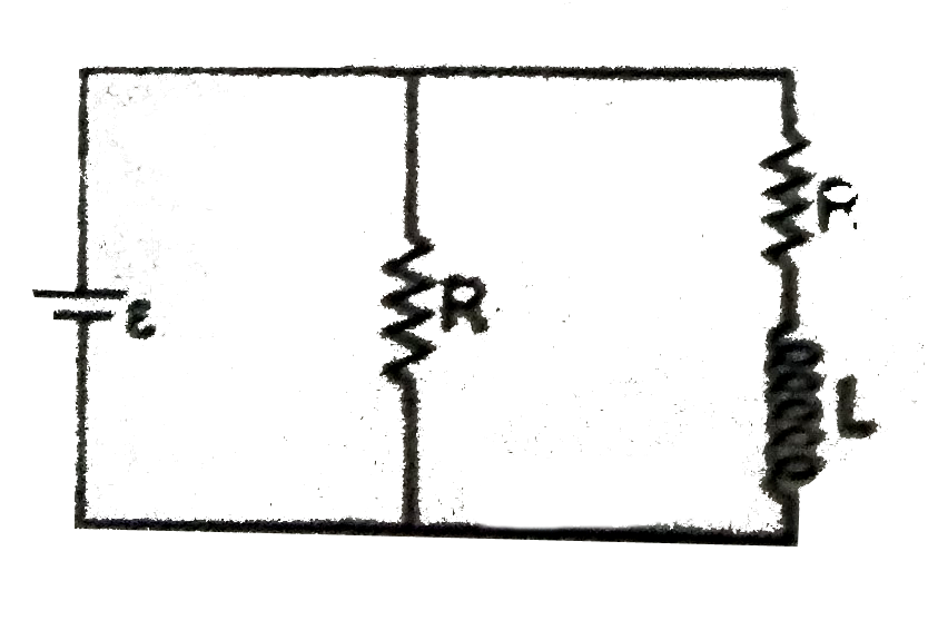 Atime constant is L/RBtime constant is 2L/RCsteady state current in inductor is 2ε/RDsteady state current in inductor is ε/2R
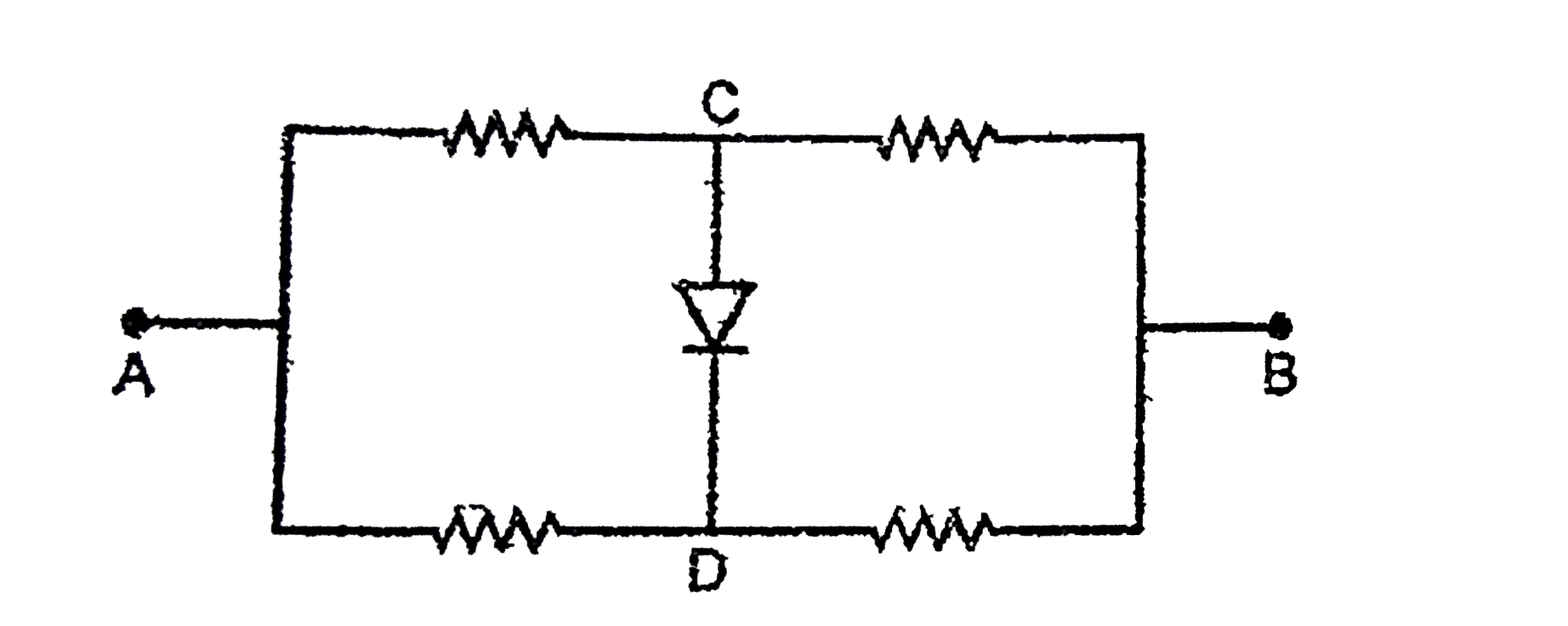
Four equal resistors, each of resistance 10 ohm are connected as shown in the adjoining circuit diagram. Then the equivalent resistance between points A and B is-A40 ohmB20 ohmC10 ohmD5 ohm
The circuit shown below acts as
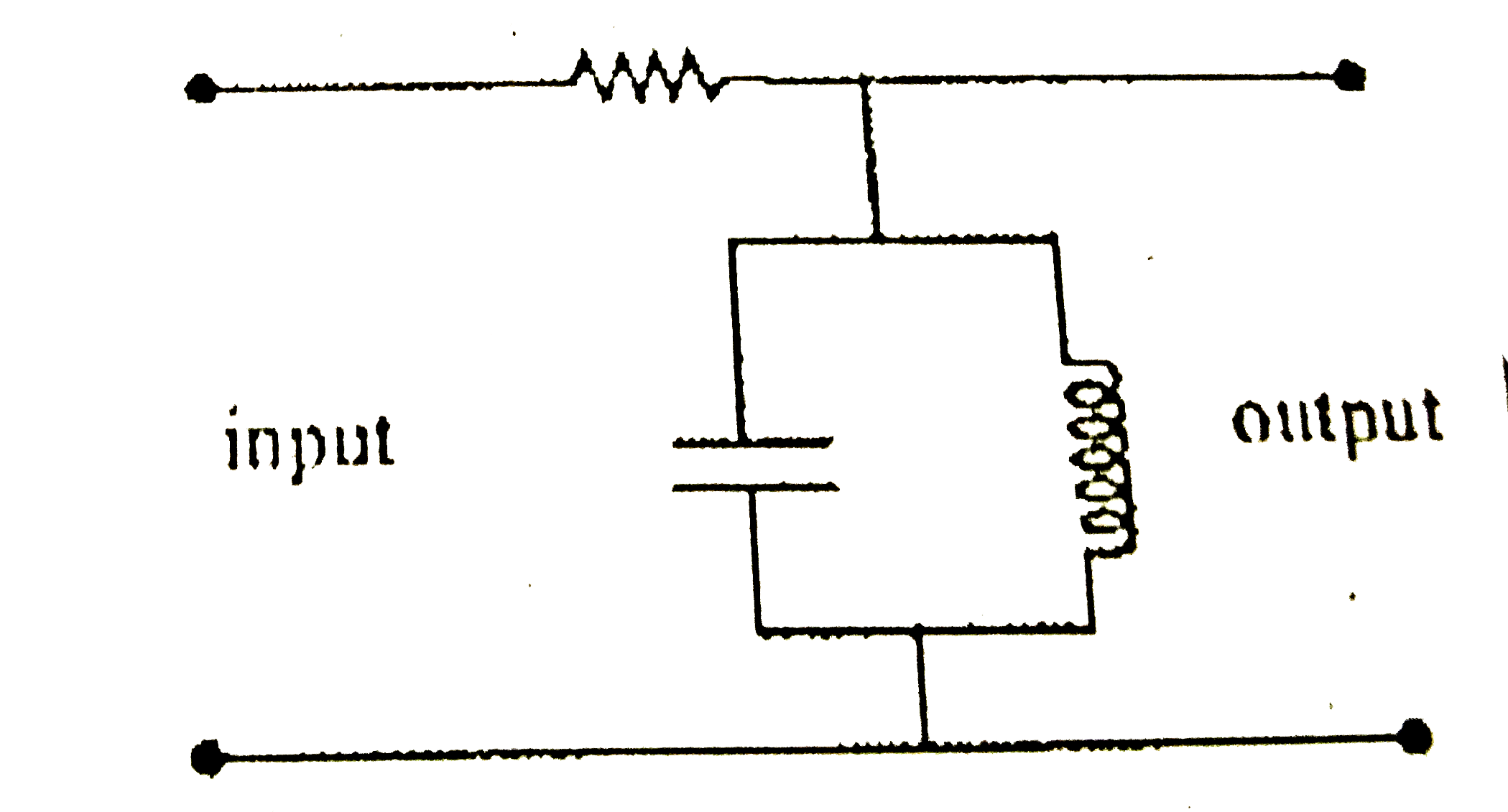
View SolutionThe circuit shown below acts as
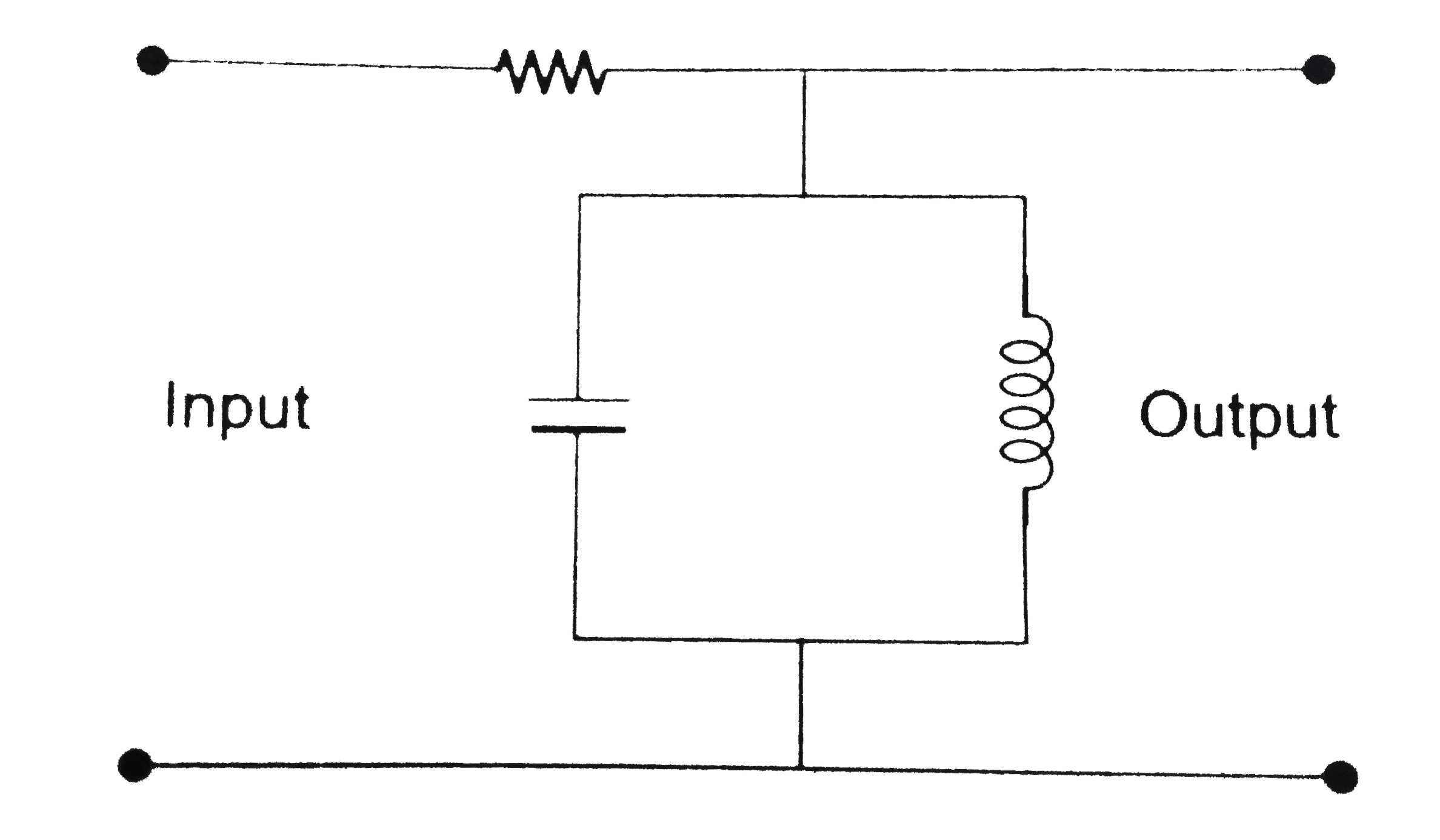
View SolutionThe circuit shown below will act as

View SolutionAn ideal ammeter is connected in a circuit as shown in circuit diagram. What will be the reading of ammeter (in S.I units)
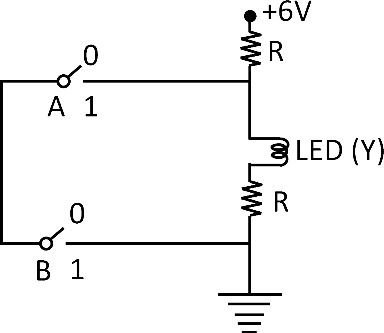
View SolutionThe correct Boolean operation represented by the circuit diagram drawn is
View Solution

