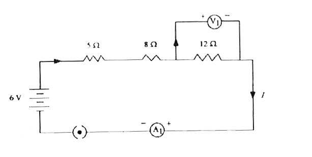
Redraw the circuit of question 1, putting in an ammeter to measure the current through the resistors and a voltmeter to measure potential difference across the 12 Ω resistor. What would be the readings in the ammeter and the voltmeter?Solution in Kannada
An ammeter should be connected in the circuit in series with , the resistors. To measure the potential difference across the resistor it should be connected in parallel, as shown in the following figure .

The resistances are connected in series. Ohm.s law can be used to obtain the readings of ammeter and voltmeter
According to Ohm.s law,
V=IR, where, Potential difference
V=6V
Current flowing through the ciruit/ resistors=I
Resistance of the circuit,
R=5+8+12=25Ω
I=V/R=6/25=0.24
A potential difference across 12Ω resistor=V1 current flowing through the 12Ω resistor, I=0.24 A
V1=IR=0.24×12=2.88V
Therefore, the reading of the ammeter will be 0.24A. The reading of the voltmeter will be 2.88V
Similar Questions
Redraw the circuit of Q.12, putting in an ammeter to measure the current through the resistors and a voltmeter to measure the voltage across the 12ohm resistor. What would be the readings in the ammeter and the voltmeter ?
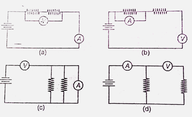
View SolutionWhich circuit diagram shows voltmeter V and ammeter A correctly positioned to measure the total potential difference of the circuit and the current through each resistor?
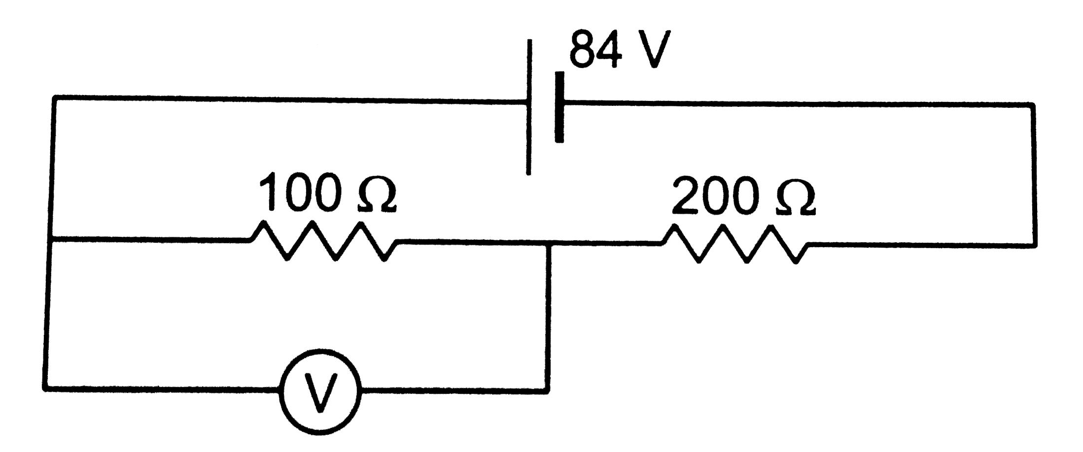
View SolutionA voltmeter of resistances 400(Ω)is used to measure the potential difference across the 100(Ω)resistor in the circuit shown in figure.(a) What will be the reading of the voltmeter ?(b) What was the potential difference across 100(Ω)before the voltmeter was connected ?

View SolutionRedraw the circuit of 9.39, putting in an ammeter to measure the current through the resistors and a voltmeter to measure the potential difference across the 12Omega resistor. What would be the readings in the ammeter and the voltmeter ?
View SolutionTwo resistors 400Omega and 800Omega are connected in series with a 6V battery. It is desired to measure the current in the circuit. An ammeter of 10Omega resistance is used for this purpose figure. What will be the reading in the ammeter? Similarly, if a voltmeter of 10,000Omega resistance is used to measure the potential difference across the 400Omega resistor, what will be the reading in the voltmeter?
View SolutionIn the circuit given below the ammeter and voltmeter are ideal measuring devices. The reading of the voltmeter is
View SolutionVoltmeter V and Ammeter A are used to measure the total potential difference of the circuit and the current through each resistor. Which is the correct circuit ?

View SolutionRedraw the circuit, putting in an ammeter to measure the current through the resistors and a voltmeter to measure the potential difference across the 12Ω resistor. What would be the readings in the ammeter and the voltmeter?
View Solution

