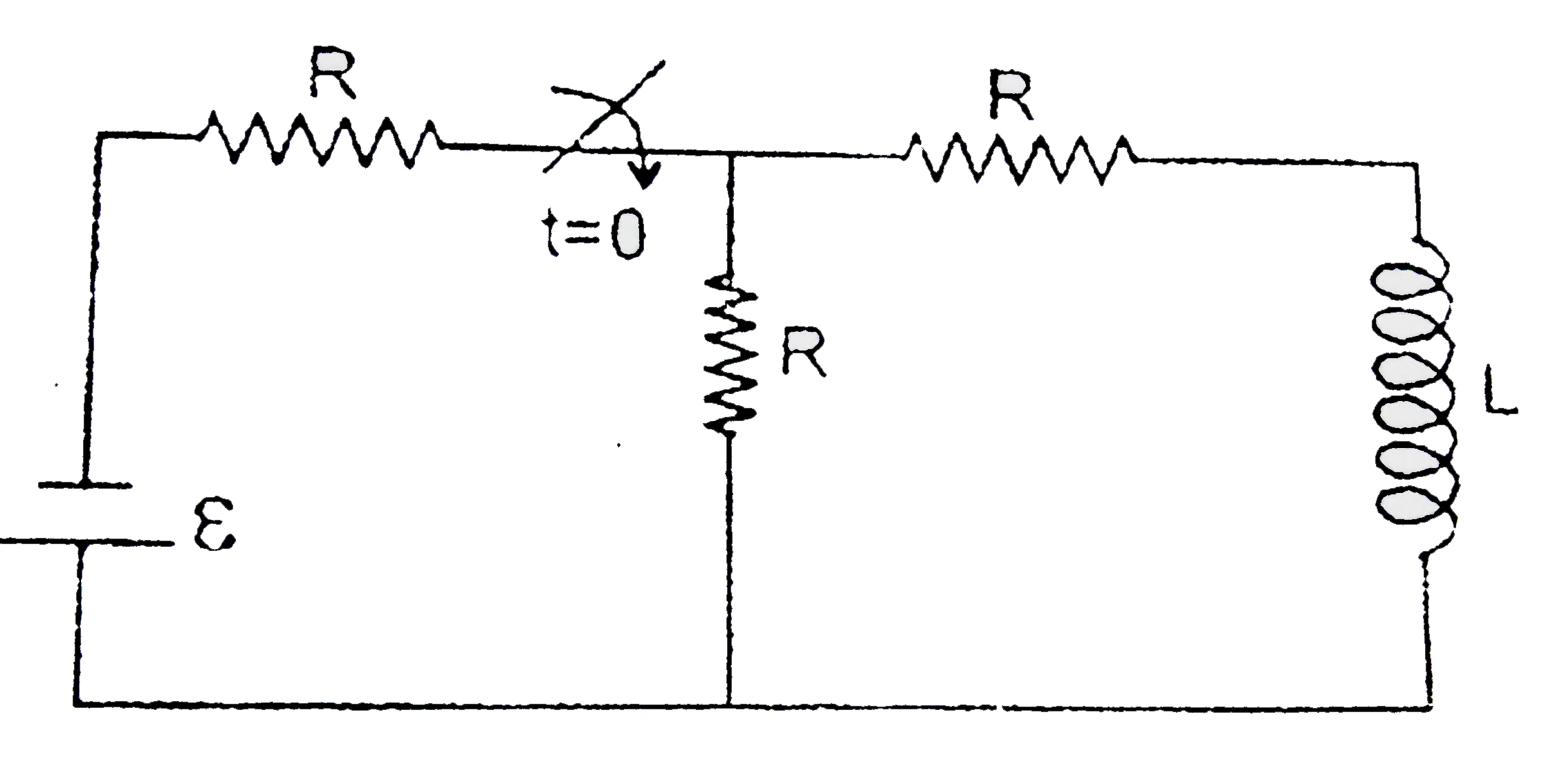
In the following circuit (Fig.) the switch is closed at . Find the current and at and at . Initially, all current are zero.

Video Solution
Text Solution
At t=0
is zero, since current cannot suddenly change due to the inductor.
(from KCL)
applying KVL in the part ABEF we get .
At
will become constant and hence potential difference across the inductor will be zero. It is just like a simple wire and the circuit can be solved assuming it to be like shown in the following diagram.
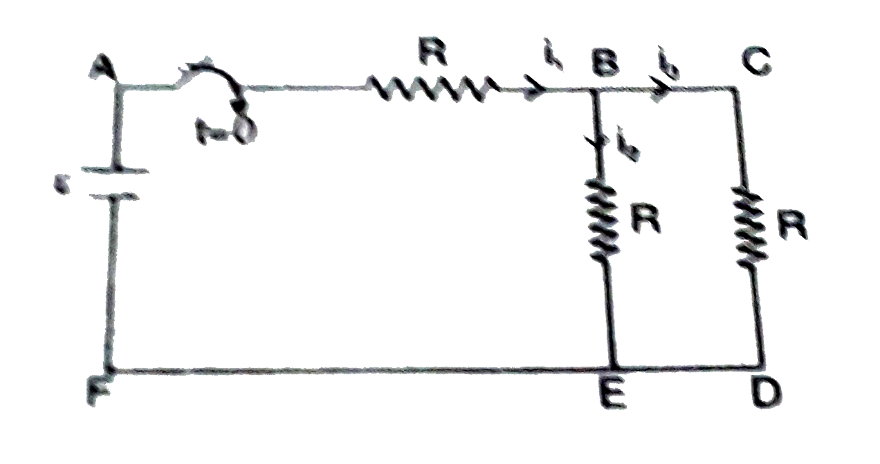
|
Similar Questions
Knowledge Check
In the circuit shows in Fig the switch is closed at t=0.
 AAt t=0,I1=I2=0BAt any time t,I0I2=L2L1CAt any time t, I1+I2=εRDAt t=∞,I1 and I2 are independent of L1 and L2
In the given circuit Fig the switch is closed at t=0. Choose the correct answers.
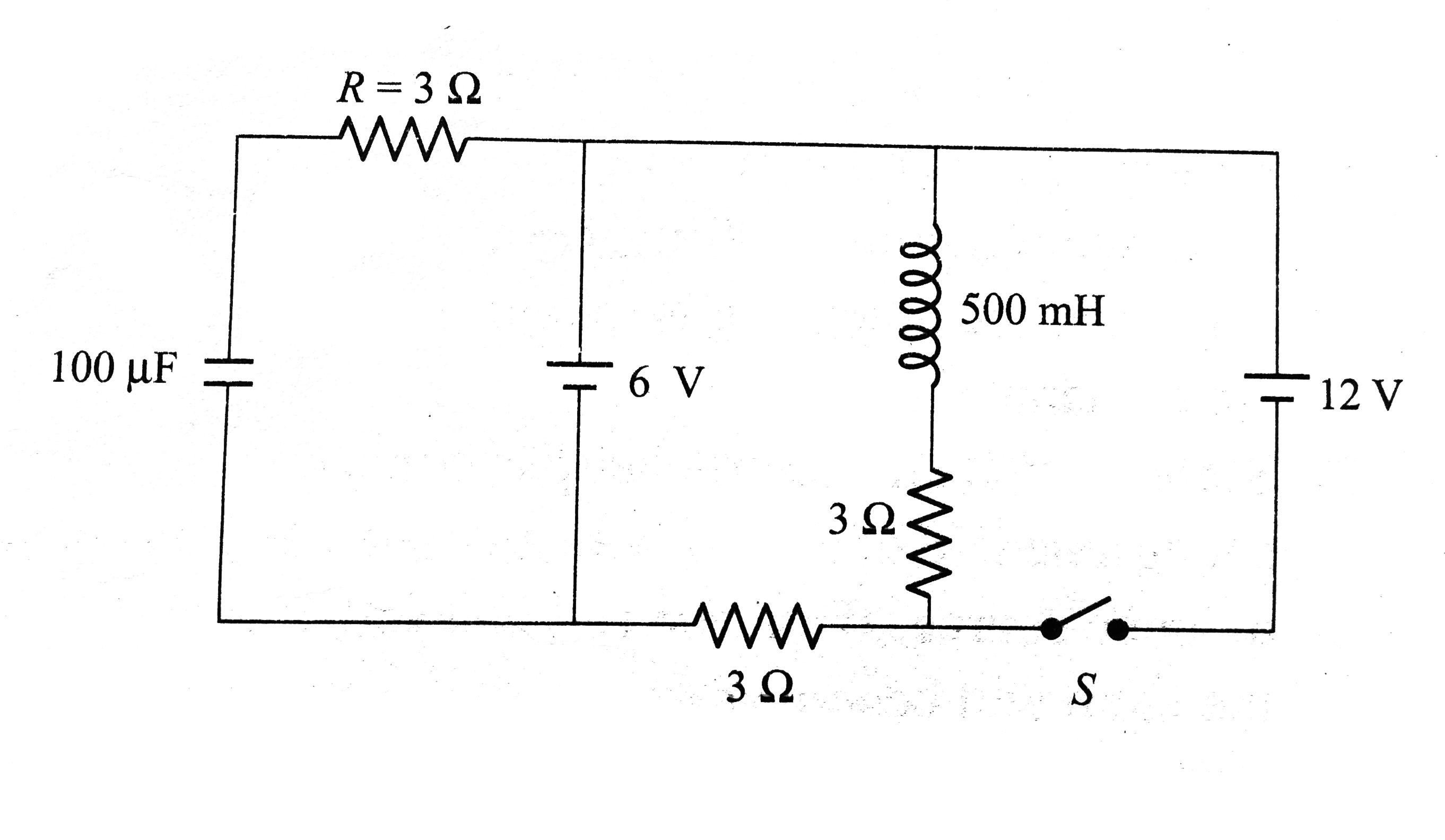 ACurrent in the inductor when the circuit reaches the steady state is 4A.BThe net change in flux in the inductor is 1.5Wb.CThe time constant of the circuit after closing S is 555.55sDThe charge stored in the capacitor in steady state is 1.2mC.
In the circuit shown, the switch is closed at t=0, the currents I1,I2 and I3 are
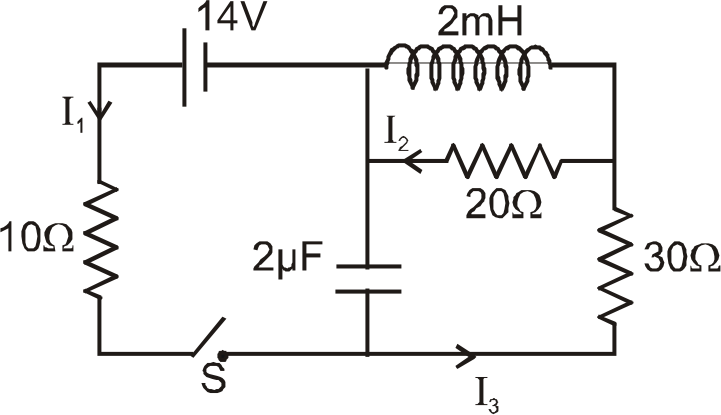 A1.4A,0,0B1.4 A,0.70 A,0.70 AC0,0,0D1.2A,0.6A,0.6A
In the following circuit (Fig.)the switch is closed at t=0. Intially, there is no current in inductor. Find out the equation of current in the inductor coil as s function of time.
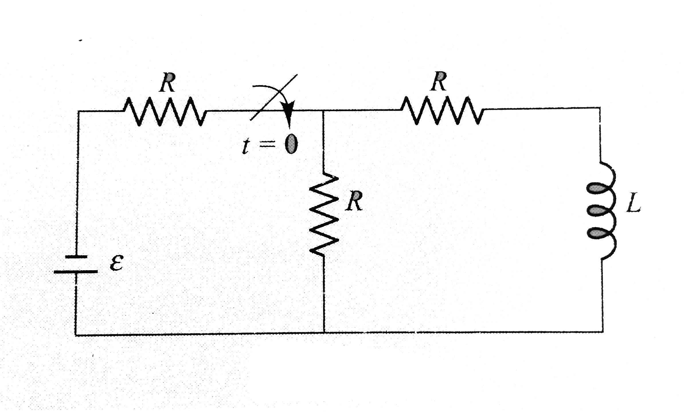
View SolutionIn the following circuit the switch is closed at t=0.Intially there is no current in inductor.Find out current the inductor coil as a function of time.
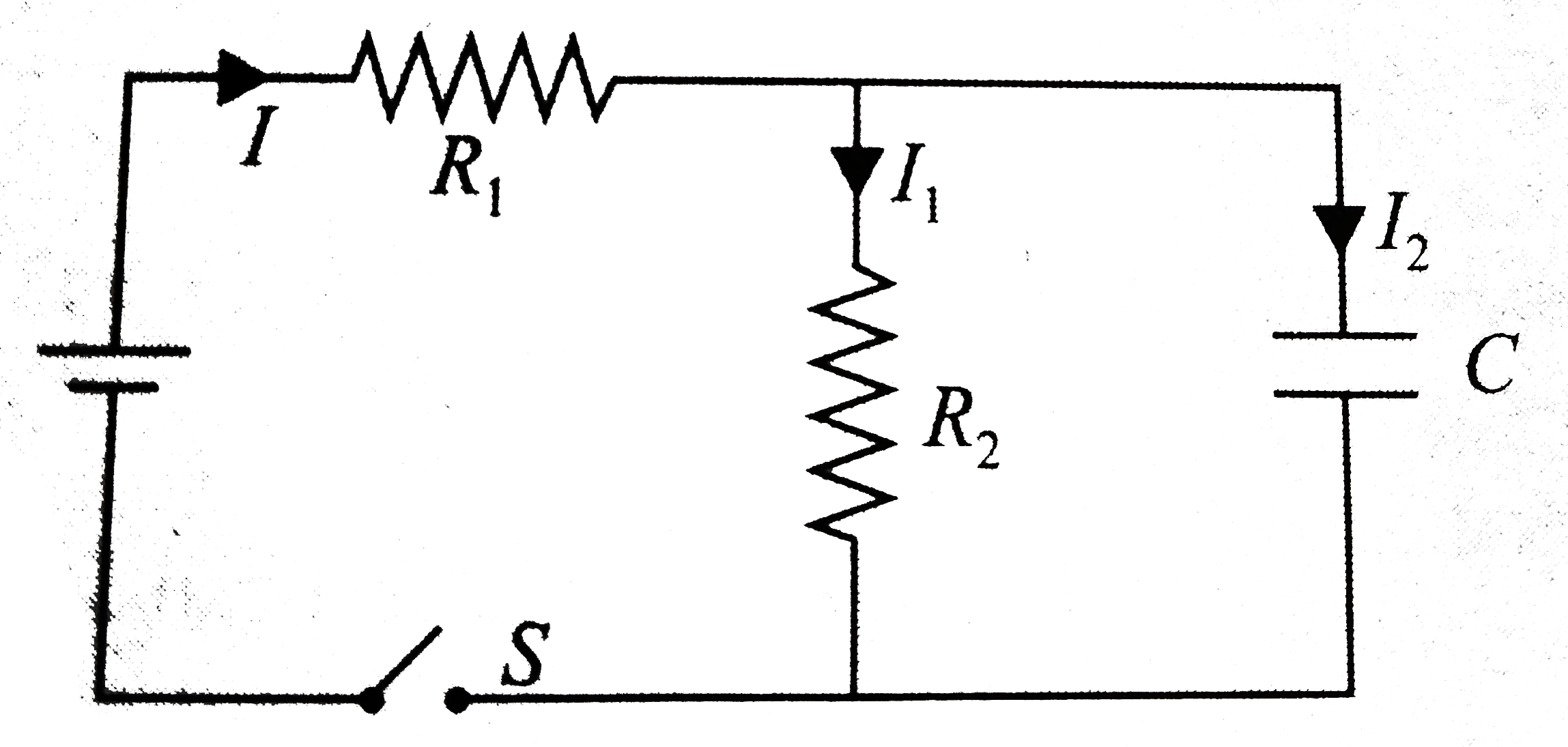
View SolutionConsider the circuit shown in fig. If the switch is closed at t =0, then calculate the values of I,I1 and I2 at a. t =0 , b. =∞
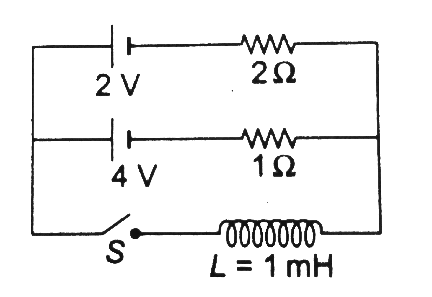
View SolutionIn the circuit shown, switch S is closed at time t=0. Find the current through the inductor as a function of time t.
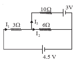
View SolutionFind the current I1, I2, & I3, in the circuit.
View Solution

_PHY_E06_157_Q01.png)