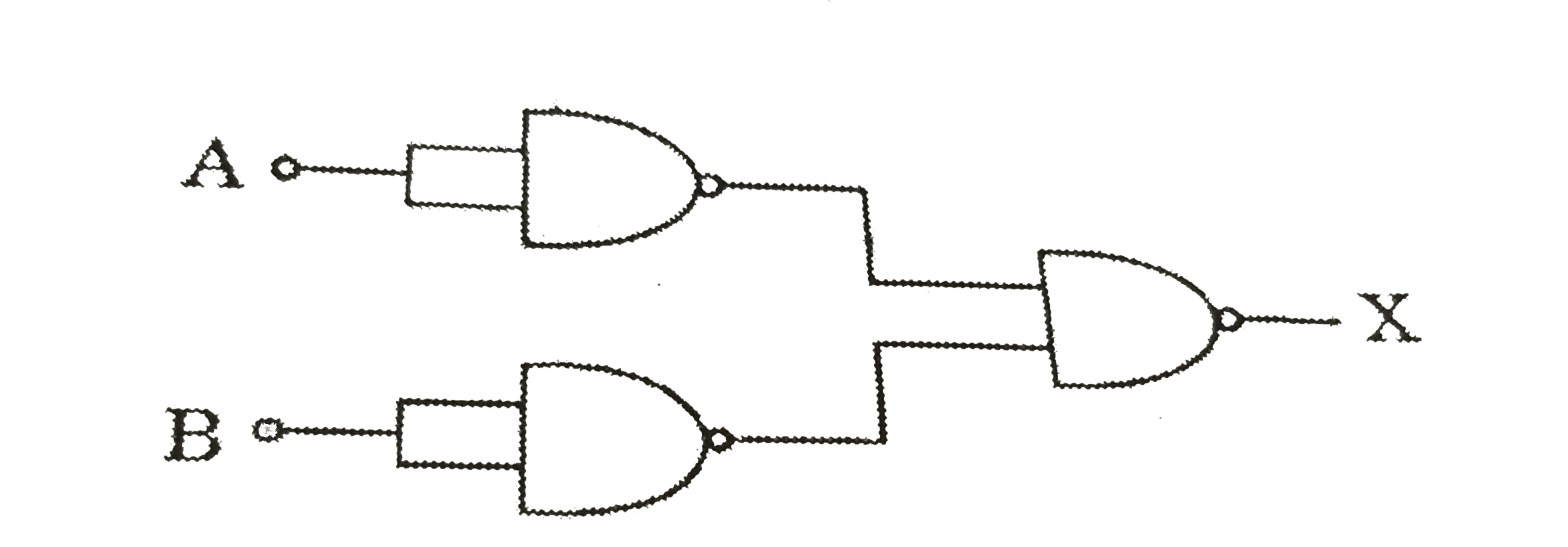
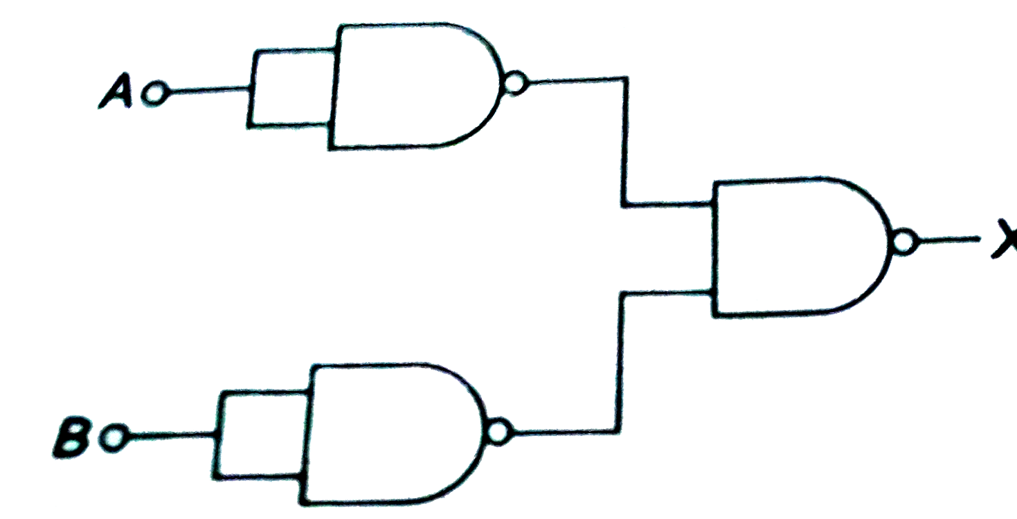
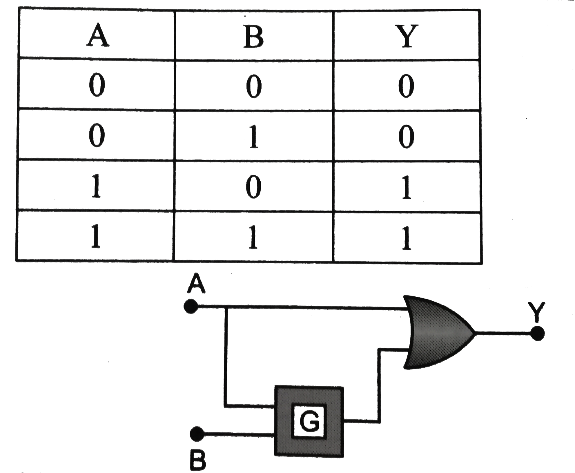
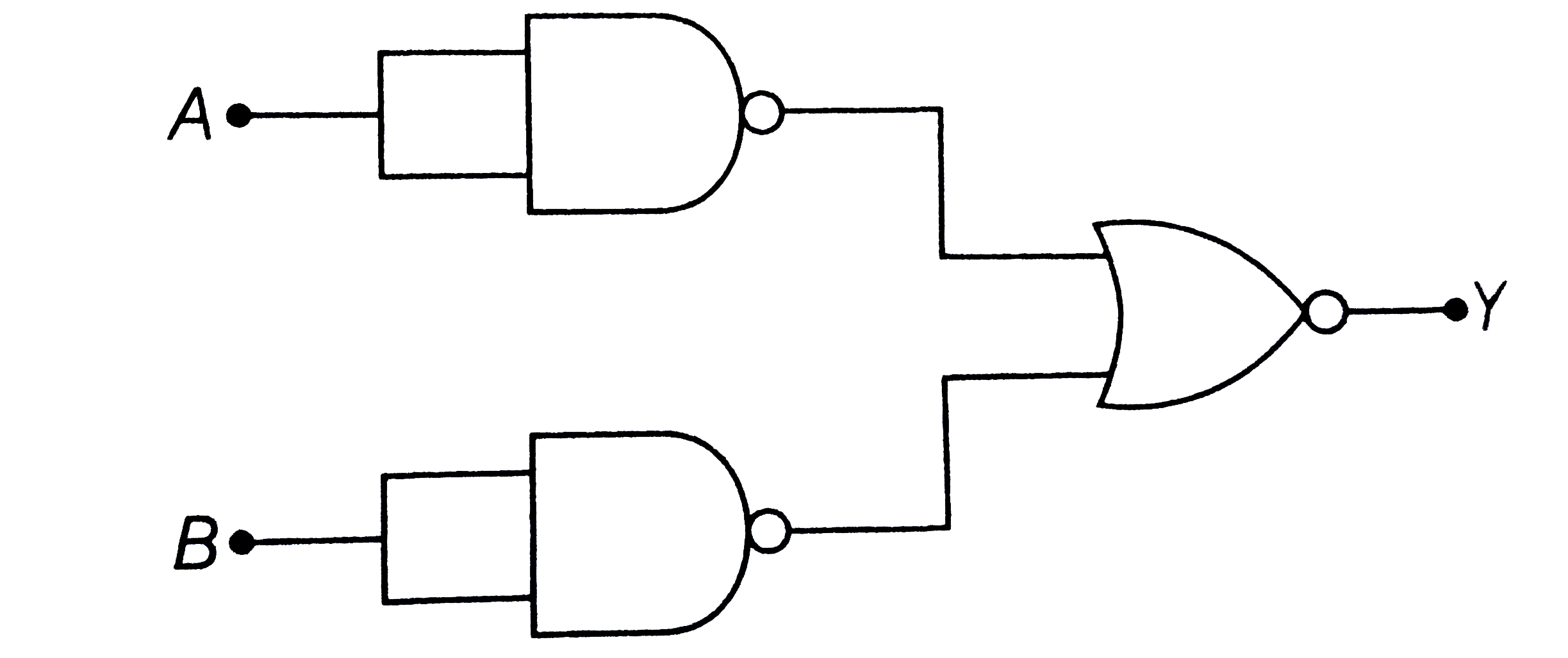
Identify the logic gate G in the combination of gates shown in fig. The truth table is shown here
A
OR gates
B
AND gate
C
NOT gate
D
NOR gate
Video Solution
Text Solution
The correct Answer is:B
Here Y is the output of G
|
Topper's Solved these Questions
- SEMICONDUCTOR ELECTRONICSBOOK - NARAYNACHAPTER - SEMICONDUCTOR ELECTRONICSEXERCISE - EXERCISE -2 (C.W) INTRINSIC, EXTRINSIC SEMICONDUCTONS)
2 Videos
- SEMICONDUCTOR ELECTRONICSBOOK - NARAYNACHAPTER - SEMICONDUCTOR ELECTRONICSEXERCISE - EXERCISE -2 (C.W) (JUNCTION DIODES)
8 Videos
- SEMICONDUCTOR ELECTRONICSBOOK - NARAYNACHAPTER - SEMICONDUCTOR ELECTRONICSEXERCISE - EXERCISE -1 (H.W) (TRANSISTORS)
11 Videos
- SEMI CONDUCTOR DEVICESBOOK - NARAYNACHAPTER - SEMI CONDUCTOR DEVICESEXERCISE - Level-II (H.W)
36 Videos
- WAVE OPTICSBOOK - NARAYNACHAPTER - WAVE OPTICSEXERCISE - Exercise - 4 Polarisation
9 Videos
Similar Questions
Knowledge Check
The combination of gates shown below yields
 AOR gateBNOT gateCXOR gateDNAND gate
The combination of gates shown here are equivalent to
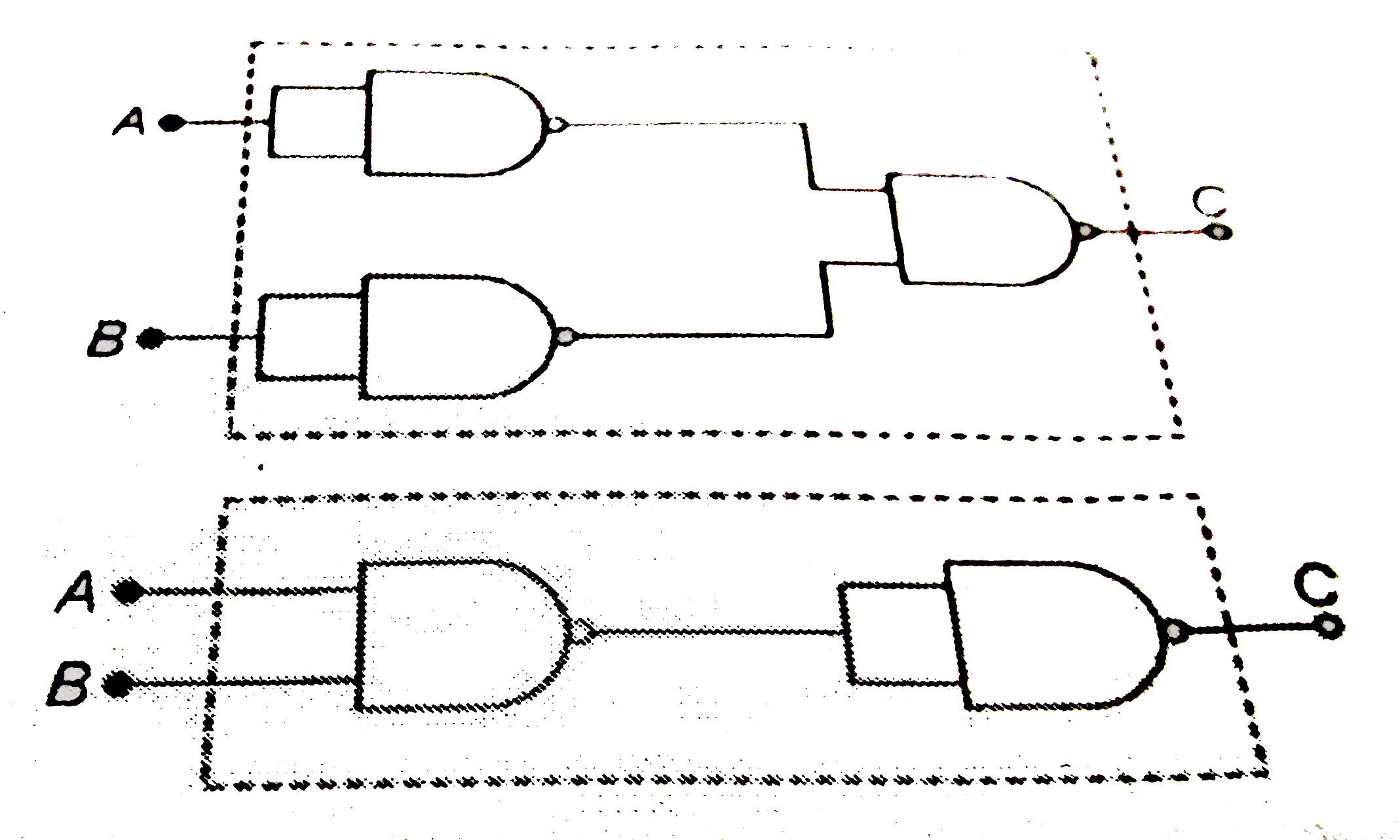 AOR gate and an AND gate respectivelyBAND gate and a NOT gate respectivelyCAND gate and an OR gate respectivelyDOR gate and a NOT gate respectively
The combination of the gates shown will produce
_E01_427_Q01.png) AOR gateBAND gateCNOR gateDNAND gate
AOR gateBAND gateCNOR gateDNAND gate
The output of the combination of the gates shown is

View SolutionThe combination Of NAND gates shown in the figure

View SolutionThe combination of the gates shown in the figure results in
View SolutionThe combination of the gates shown will produce

View SolutionThe combination of the gates shown will produce
_E01_428_Q01.png)
View Solution

