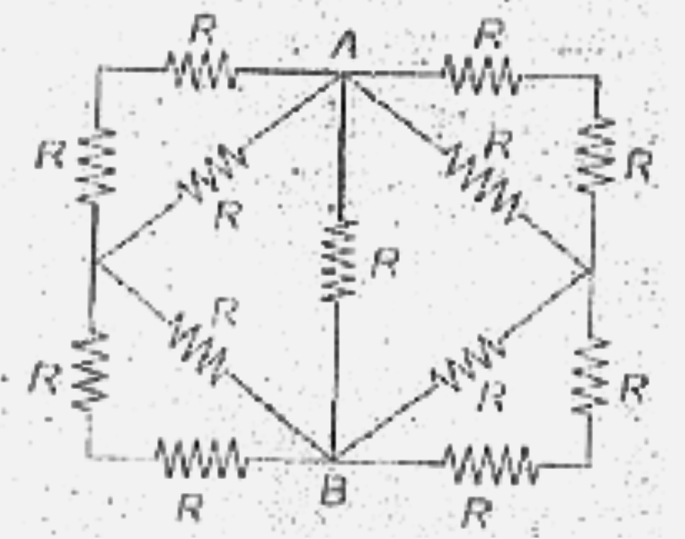
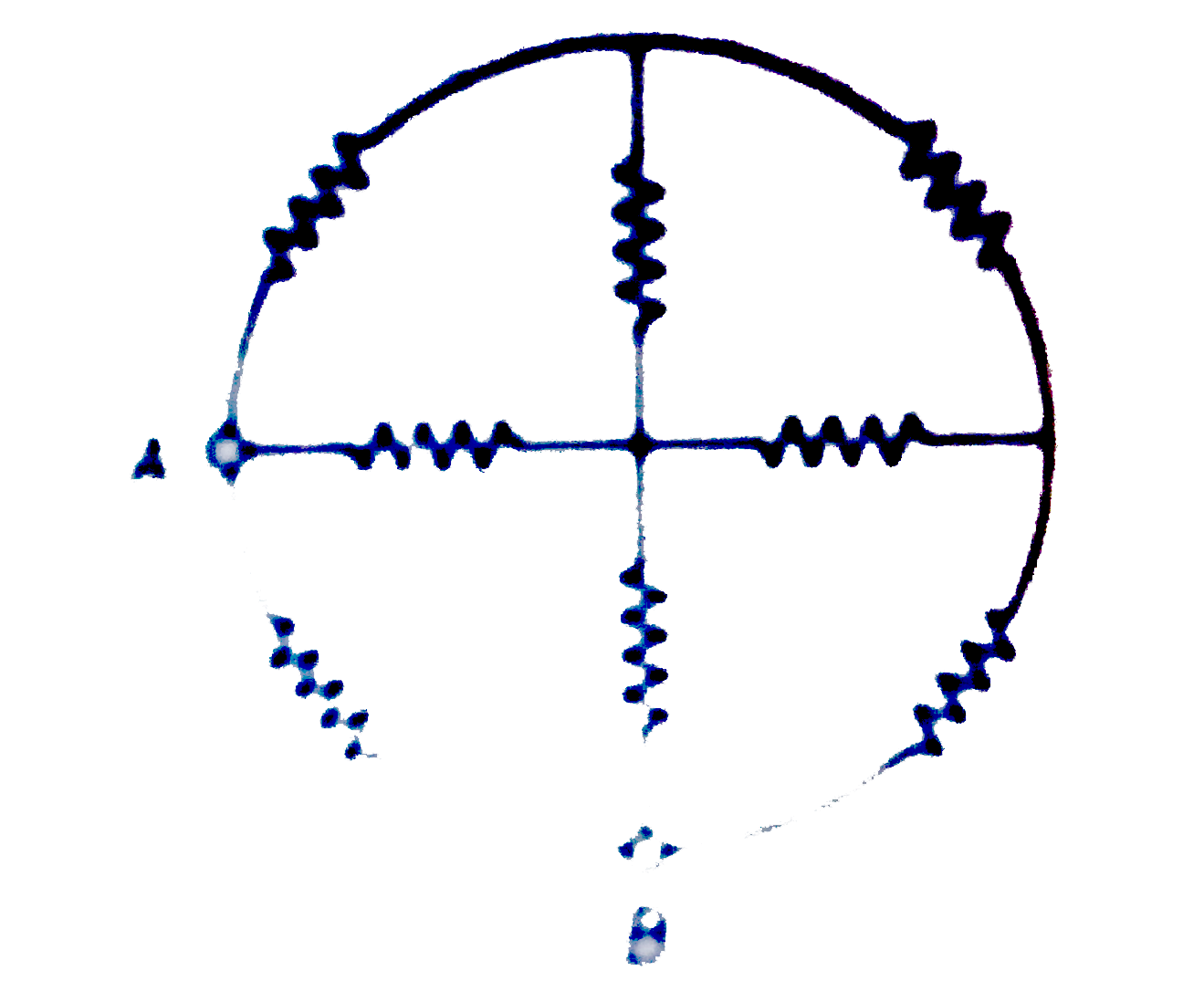
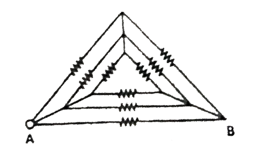
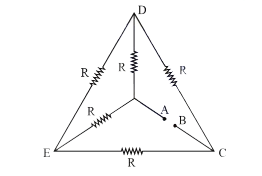
Nine resistors each of resistance R are connected in the circuit as shown in fig. The net resistance between A and B is
R
2R9
3R5
7R6
The correct Answer is:C
Step by step video & text solution for Nine resistors each of resistance R are connected in the circuit as shown in fig. The net resistance between A and B is by Physics experts to help you in doubts & scoring excellent marks in Class 12 exams.
Updated on:21/07/2023Similar Questions
Knowledge Check
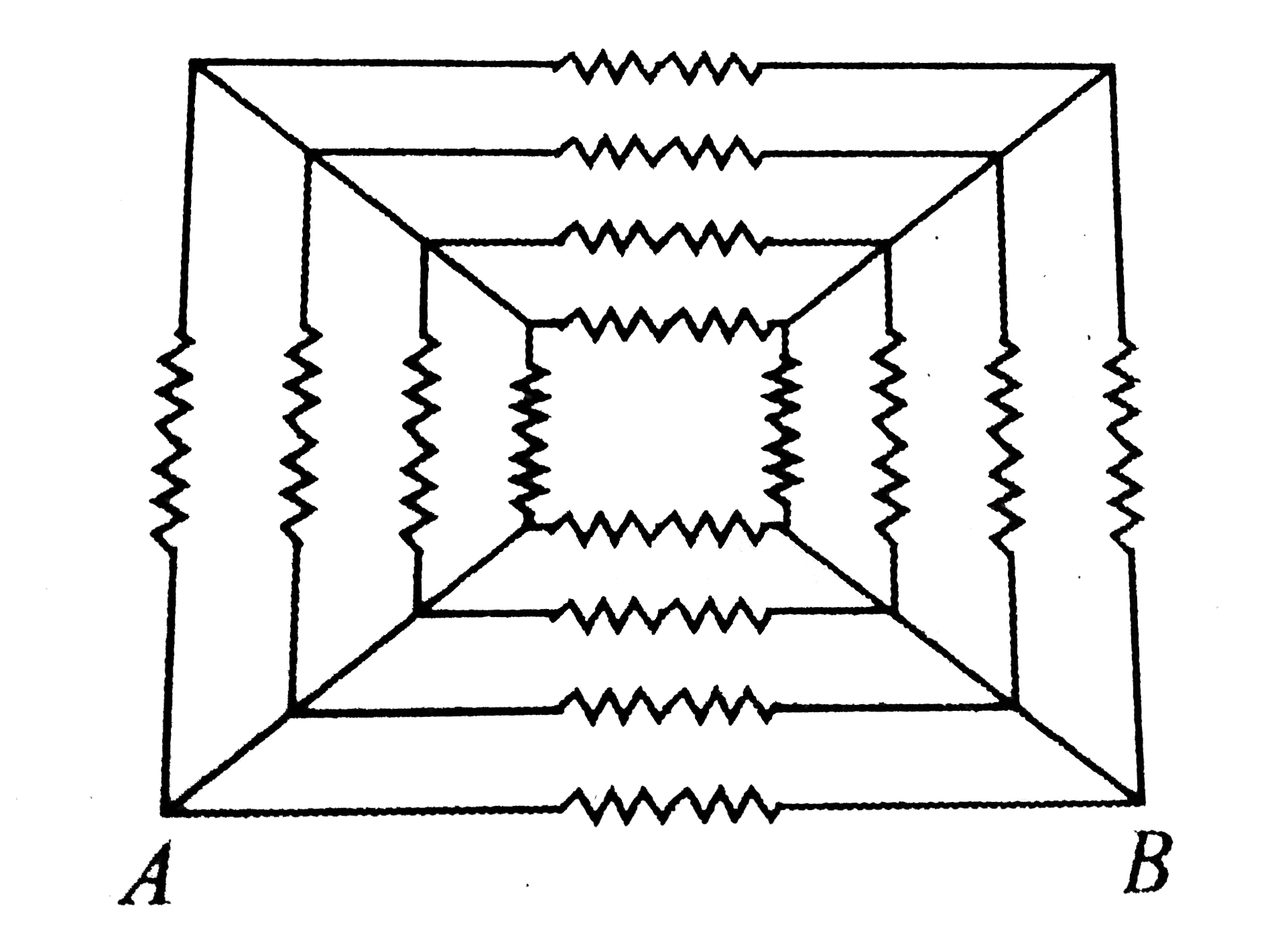
Sixteen resistor, each resistane 16Ω are connected in the circuit as shown in fig. the net resistance between A and B is
 A1ΩB2ΩC3ΩDΩ
Twelve resistors each of resistance 1Ω are connected in the circuit shown in figure. Net resistance between point A and H would be
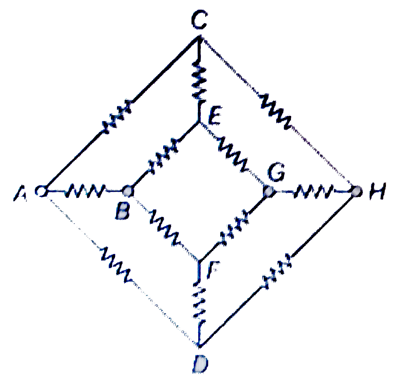 A5R3B7R6CRD3R4
Twelve resistors each of resistance 1Ω are connected in the circuit shown in figure. Net resistance between point A and H would be
 A53ΩB163ΩC157ΩD192Ω
For the circuit shown in fig. the equivalent resistance between A and C is
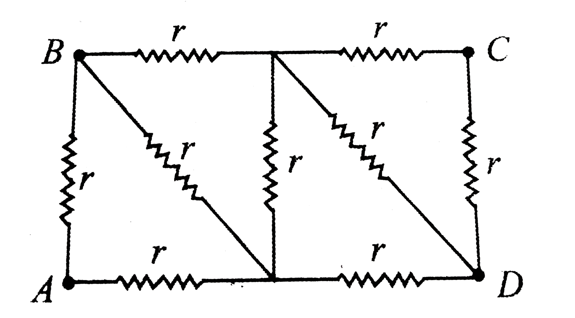
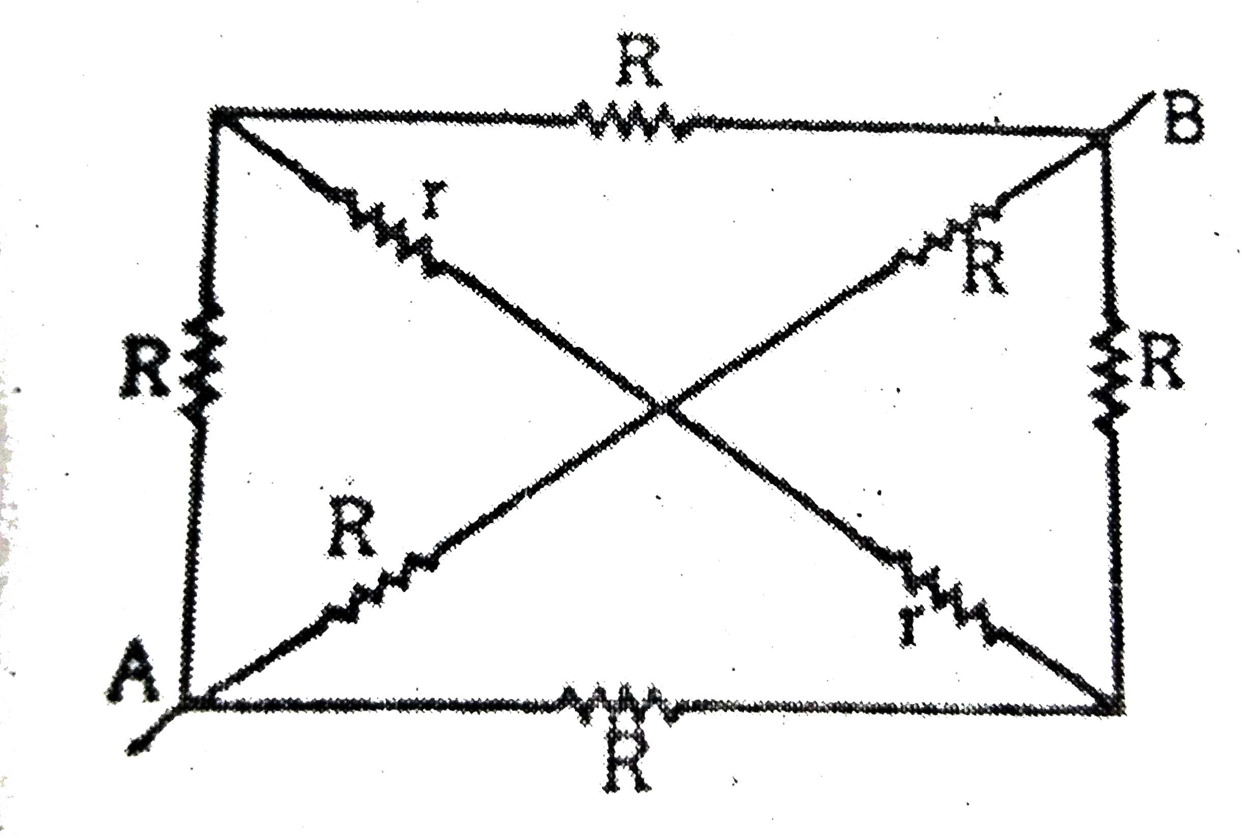
View SolutionSix resistors each of resistance R and two resistors each of resistance r are connected in the network shown below. The equivalent resistance between A and B is
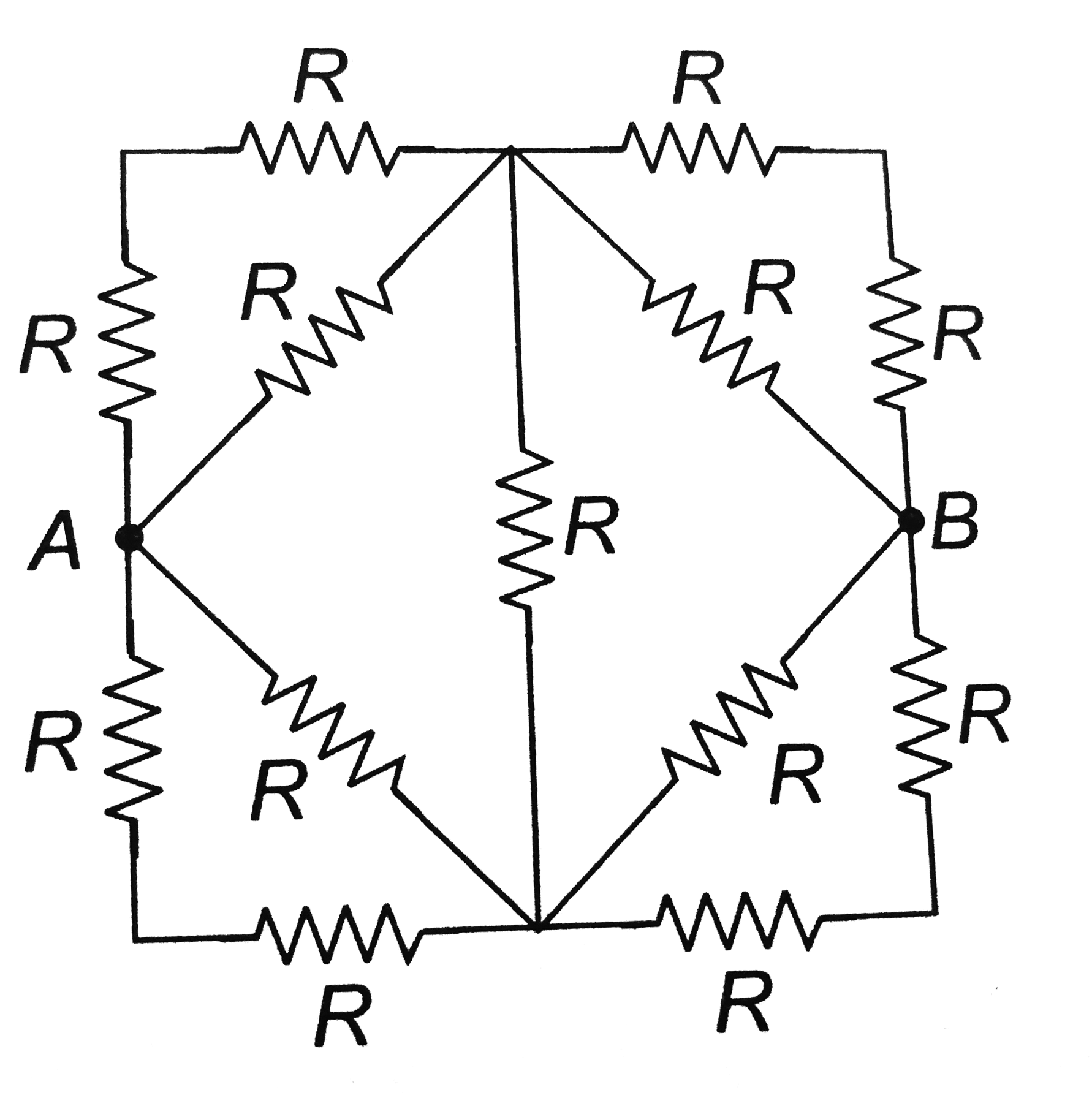
View SolutionThirteen resistances each of resistance R ohm are connected in the circuit as shown in the figure below. The effecitve resistance between A and B is
View SolutionFive equal resistances are connected in a network as shown in figure. The net resistance between the points A and B is :
View SolutionEach resistance of the circuit shown in figure is r. The equivalent resistance between A and B is
View Solution

