You are given four ammeters A, B, C and D having the least counts mentioned below :
Which of the ammeters would you prefer for doing an experiment to determine the equivalent resistance of two resistance most accurately, when connected in parallel?
Ammeter A with least count 0.25 A
Ammeter B with least count 0.5 A
Ammeter C with least count 0.05 A
Ammeter D with least count 0.1 A
The correct Answer is:C
NA
Topper's Solved these Questions
- THE HUMAN EYE AND THE COLOURFUL WORLD BOOK - LAKHMIR SINGH & MANJIT KAURCHAPTER - THE HUMAN EYE AND THE COLOURFUL WORLD EXERCISE - Long Answer Type Question
3 Videos
- THE HUMAN EYE AND THE COLOURFUL WORLD BOOK - LAKHMIR SINGH & MANJIT KAURCHAPTER - THE HUMAN EYE AND THE COLOURFUL WORLD EXERCISE - NCERT Book
14 Videos
- THE HUMAN EYE AND THE COLOURFUL WORLD BOOK - LAKHMIR SINGH & MANJIT KAURCHAPTER - THE HUMAN EYE AND THE COLOURFUL WORLD EXERCISE - Long Answer Type Questions
2 Videos
- TEST PAPER 4BOOK - LAKHMIR SINGH & MANJIT KAURCHAPTER - TEST PAPER 4EXERCISE - SECTION A
10 Videos
Similar Questions
Give any four precautions taken by a student to perform an experiment to determine the resultant resistance of two resistors when connected in series.
View SolutionThe following instruments are available in a laboratory :
(i) Milliammeter A1 of range 0.300mA and least count 10mA
Milliammeter A2 of range 0.200mA and least count 20mA
Voltmeter V1 of range 0.3V and least count 0.3V
Which pair of instruments would be the best choice for carrying out the experiment to determine the equivalent resistance of two resistors connected in series ?
View Solution
Knowledge Check
Choose the appropriate set of apparatus for performing the experiment to determine the equivalent resistance of two resistors when connected in series :
AVoltmeter, Ammeter, Two resistors, Key, BatteryBAmmeter, Two resistors, Key, Connecting wires, Rheostat, BatteryCKey, Rheostat, Voltmeter, Two resistors, Battery, Connecting wiresDBattery, Ammeter, Connecting wires, Rheostat Voltmeter, Two resistors, KeyFour student have made the following circuit diagrams for determining the equivalent resistance of two resistors connected in series :

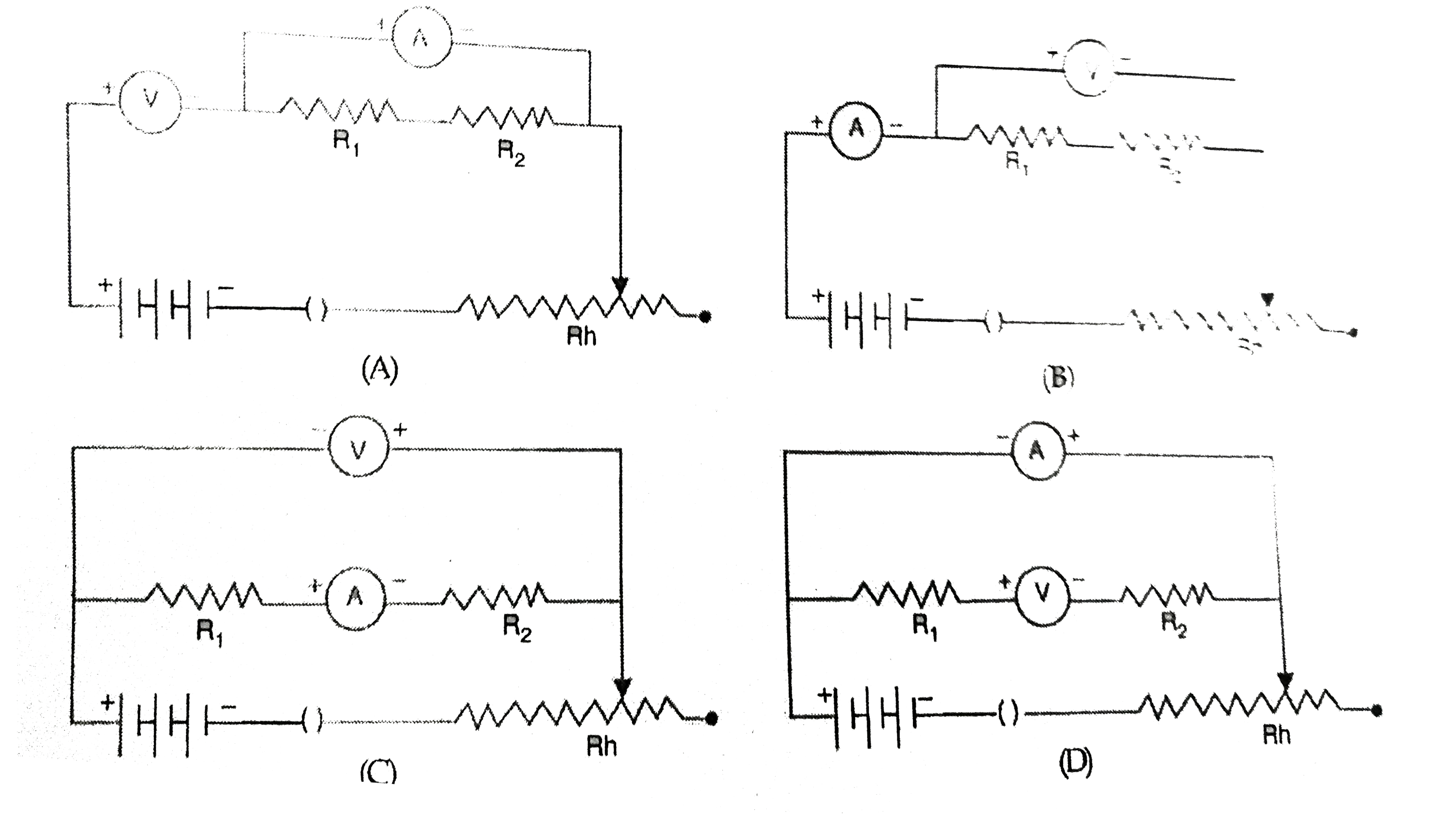
The correct circuit diagram is :AABBCCDDAssertion (A): Two resistance having value R each. Their equivalent resistance is R2.
Reason (R): Given Resistance are connected in parallel.ABoth A and R are true and R is the correct explanation of A.BBoth A and R are true but R is NOT the correct explanation of ACA is true but R is false.DA is false and R is true.
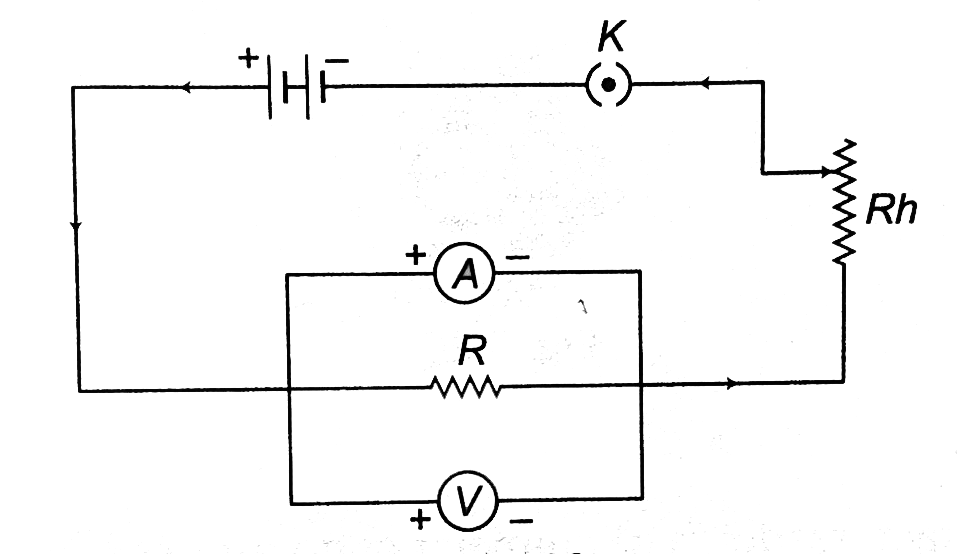
What result do you expect in above experiment if by mistake, ammeter is connected in parallel with voltmeter and resistance as shown in figure?
 .
.
View SolutionThe following pieces of apparatus are available in a laboratory :
Battery : adjustable from 0 to 6 V
Resistors : 3Ω and 6Ω
Ammeters : A1 of range 0 to 5 A , least count 0.25A
A2 of range 0 to 3 A , least count 0.1A
Voltmeters : V1 of range 0 to 10 V , least count 0.5V
v2 of range 0 to 5 V , least count 0.1 V
For the experiment to find the equivalent resistance of the parallel combination of the two given resistors, which is the best choice ?
View Solution
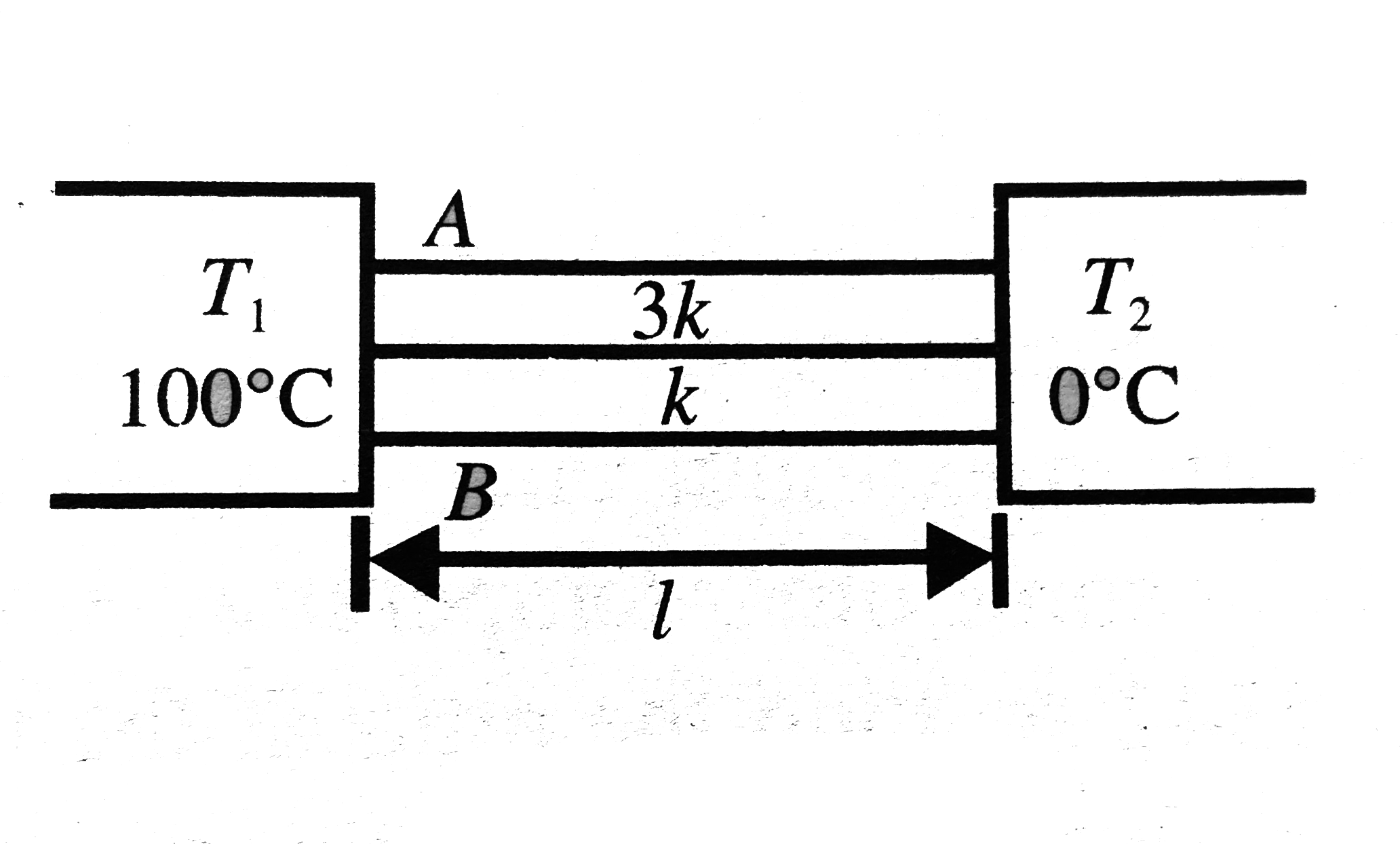
Two conductors A and B given in previous problem are connected in parallel as shown in Fig.
i. Determine the equivalent thermal resistance.
ii. Determine the heat current in each rod.
View SolutionTwo uniform wires A and B of same metal and have equal masses, the radius of wire A is twice that of wire B. The total resistance of A and B when connected in parallel is
View SolutionYou are given tha following four voltmeters to study the dependence of current (I) on the potential difference (V) across a resistor.

Which one of the above voltmeters would you prefer to use in the circuit to begin your experiment ?
View Solution
