The circuit diagram given in the figure shown the experimental setup for the measurement of unknown resistance by using a metre bridge. The wire connected between the points P and Q(PQ = 100 cm) has uniform cross-sectional area and its resistivity is directly proportional to the distance from point P. Null point is obtained with the jockey J with R1andR2 in the gaps. If R1andR2 are interchanged, the jockey has to be displaced through a distance from the previous position along the wire to establish the null point. If the ratio of R1R2=3 , the value of Δ (in cm) is: [Ignore any end corrections]
![The circuit diagram given in the figure shown the experimental setup for the measurement of unknown resistance by using a metre bridge. The wire connected between the points P and Q(PQ = 100 cm) has uniform cross-sectional area and its resistivity is directly proportional to the distance from point P. Null point is obtained with the jockey J with R1 and R2 in the gaps. If R1 and R2 are interchanged, the jockey has to be displaced through a distance from the previous position along the wire to establish the null point. If the ratio of R1/R2=3 , the value of Delta (in cm) is: [Ignore any end corrections]](https://d10lpgp6xz60nq.cloudfront.net/physics_images/VMC_PHY_XI_WOR_BOK_04_C14_E03_036_Q01.png)
50
50(2√3)
50(√5−2)
50(√3−1)
From the given circuit diagram R1R2=x2(100)2−x2 ⇒x=50√3
Also, R2R1=y2(100)2−y2⇒y=50,Δ50(√3−1)cm
Similar Questions
In a meter bridge, two unknown resistances R and S, when connected between the two gaps, gives a null point is 60 cm from one end. What is the ratio of R and S?
View SolutionIn a meter bridge experiment shown below, the null point is obtained at P. The value of unknown resistance X is 2012 50 cm 1.) E
View Solution
Knowledge Check
For the accurate measurement of resistance by metre bridge, the null point should be obtained
Atowards left endBtowards right endCat the middle of wireDall of theseIn the circuit shown here, what is the value of the unknown resistor R so that the total resistance of the circuit between points P and Q is also equal to R
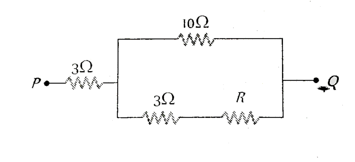 A3 ohmsB√39 ohmsC√69 ohmsD10 ohms
In the circuit shown in figure R=55Ω the equivalent resistance between the point P and Q is
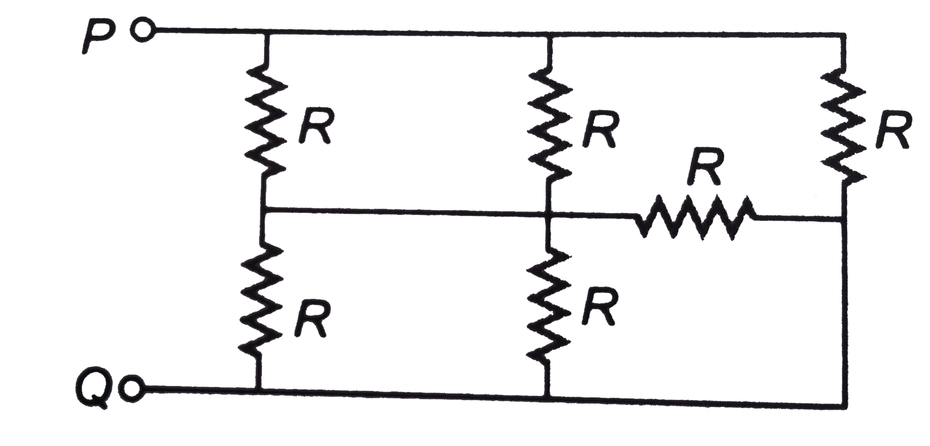 A30ΩB35ΩC55ΩD25Ω
Draw a circuit diagram of a meter bridge used to determine the unknown resistance R of a given wire. Hence derive the expression for R in terms of the known resistance S.
View SolutionFor the network of resistance shown in the figure the equivalent resistance of the network between the points A and B is 18 ohm. The value of unknown resistance R is :
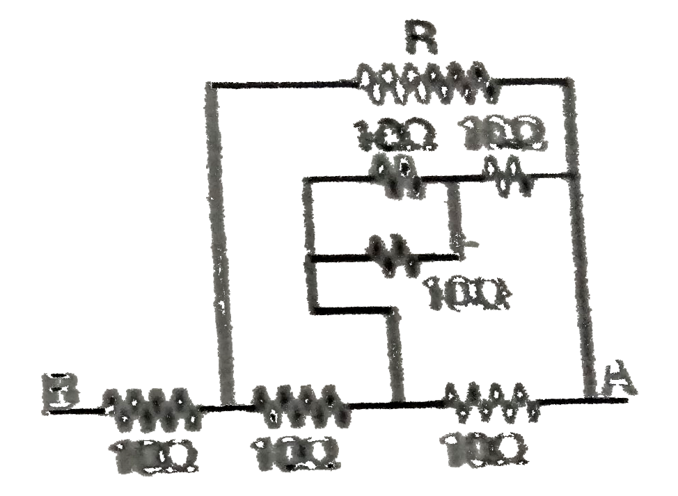
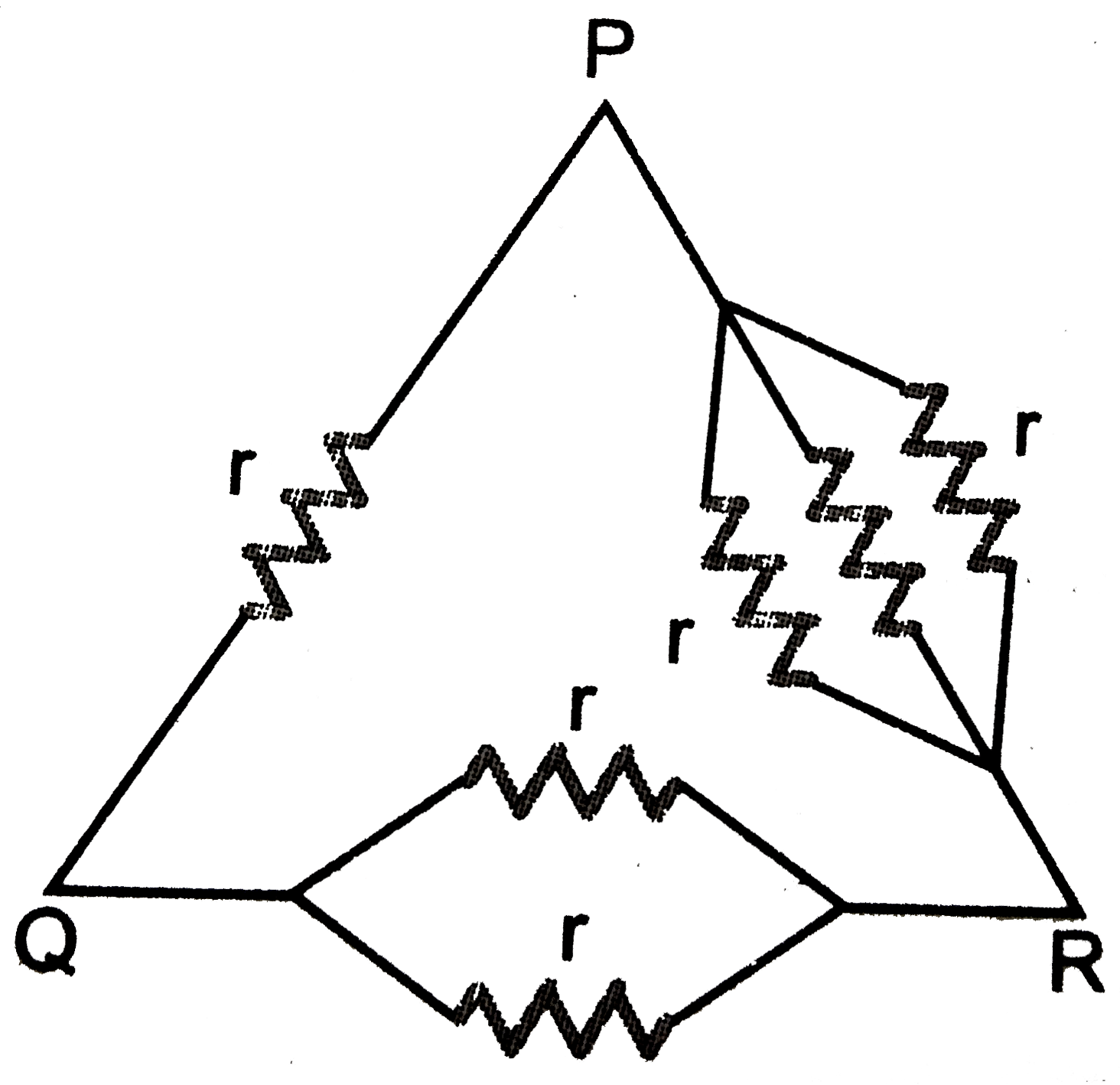
View SolutionSix equal resistance are connected between point P,QandR Then net resistance will be maximum between
View SolutionTwo equal resistances are introduced in two gaps of a metre bridge. The shift in the null point if an equal resistance is connected in series with resistance in left gap is
View Solution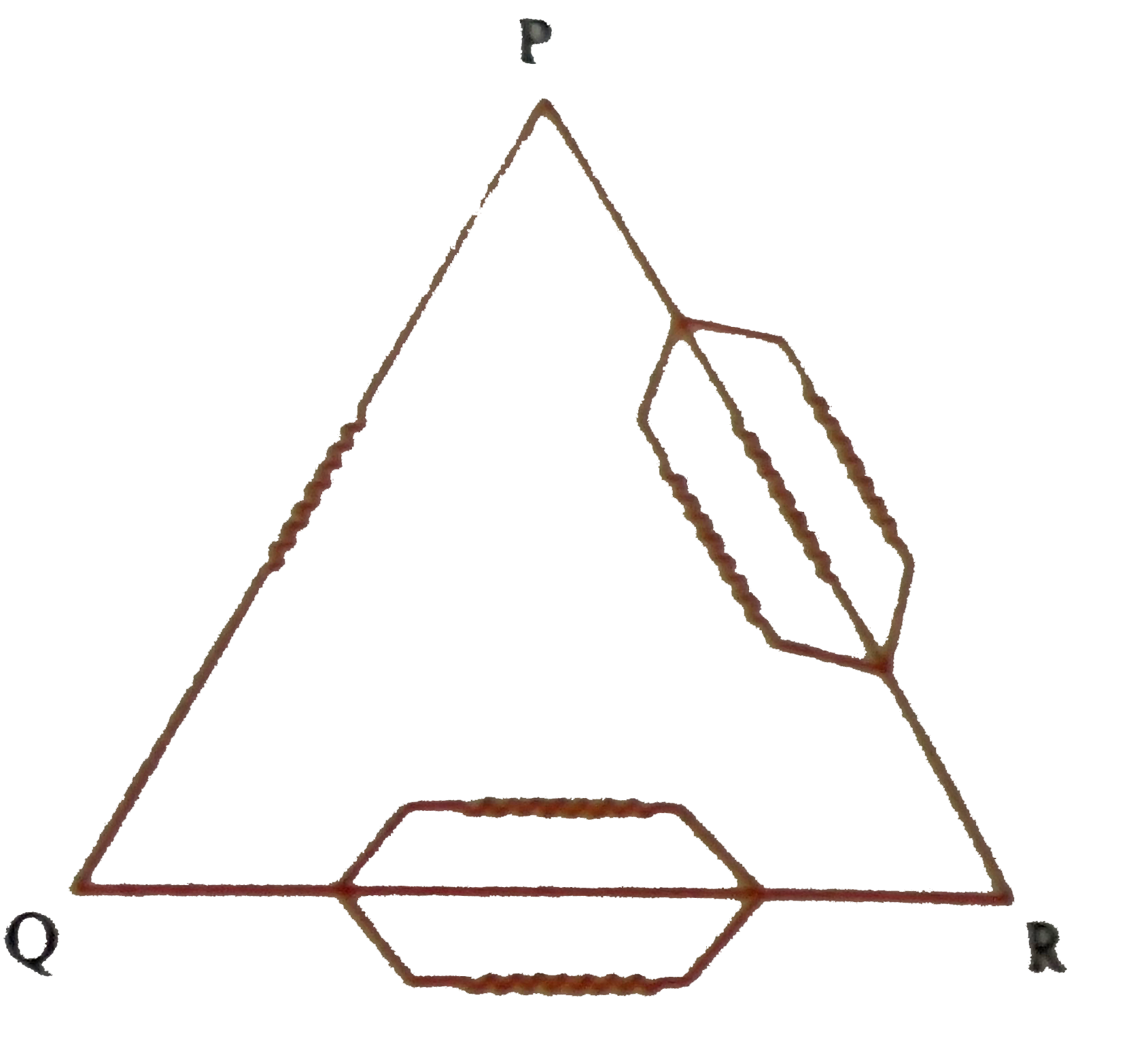
Six equal resistances are connected between points P, Q and R as shown in the figure. Then the net resistance will be maximum between
View Solution
