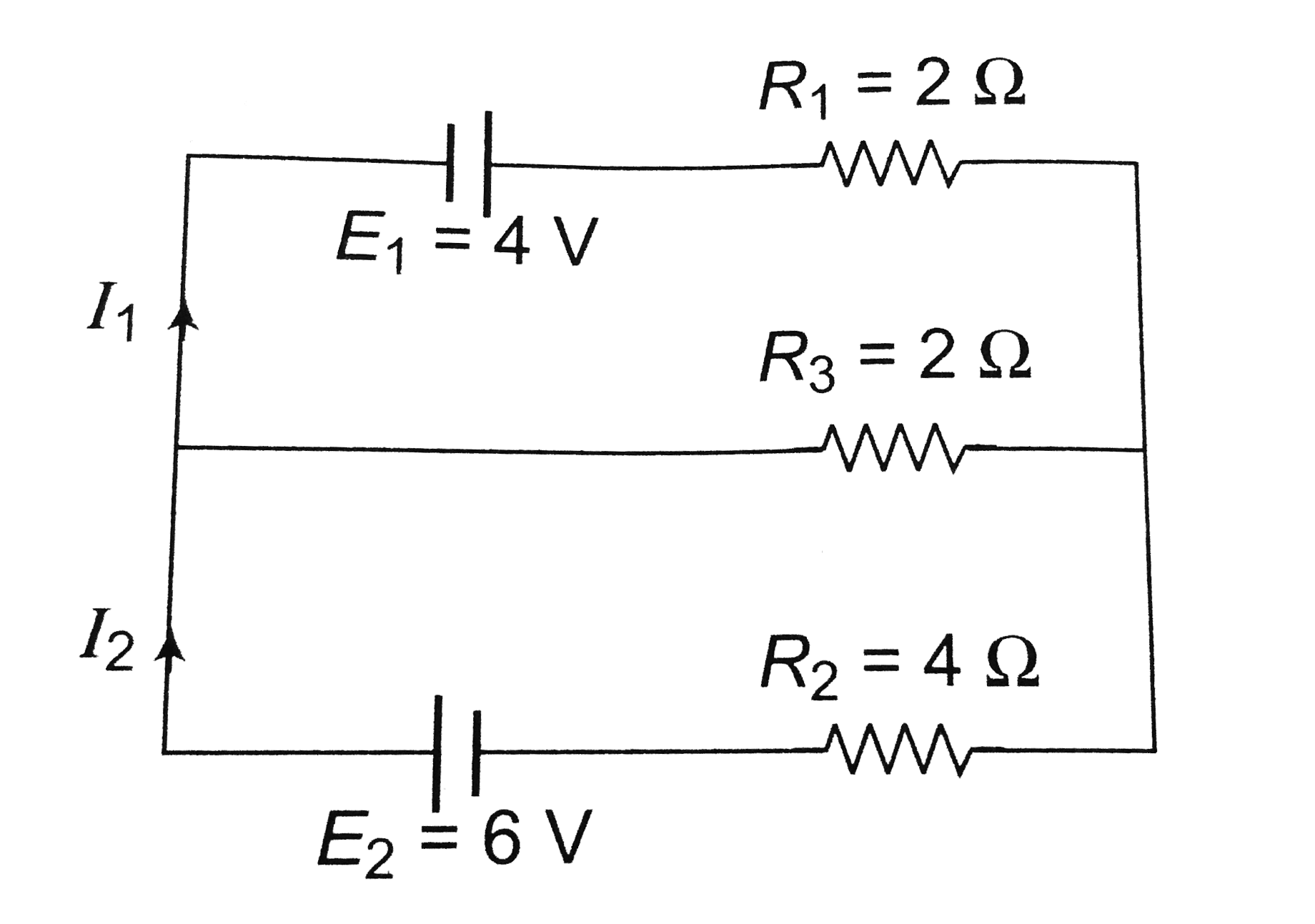
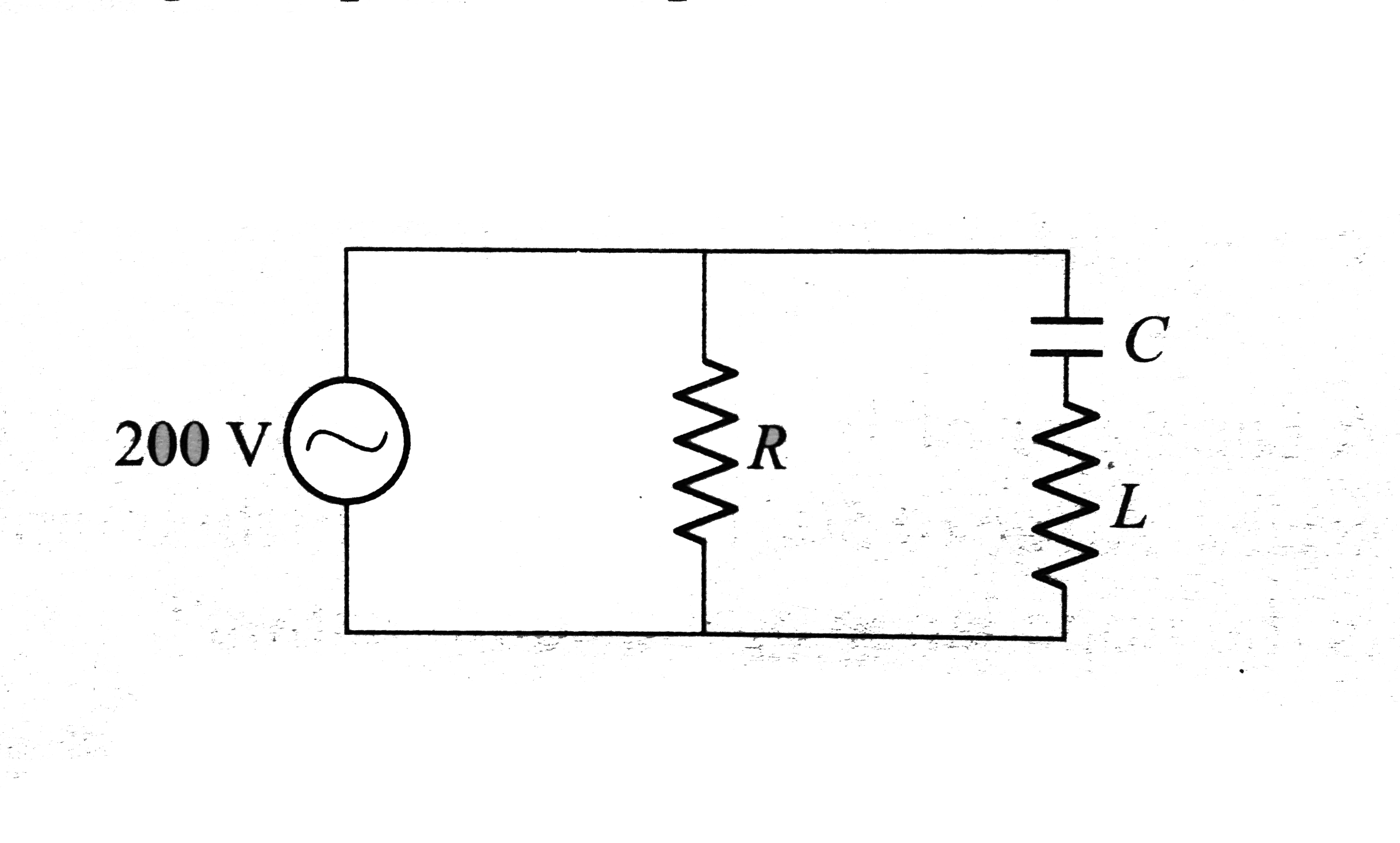
In the circuit shown in figure :
R=10Ω,L=√310H,R2=20Ω and C=√32mF. Current in L−R1 circuit is I1 in C−R1 circuit is I2 and the main current is I
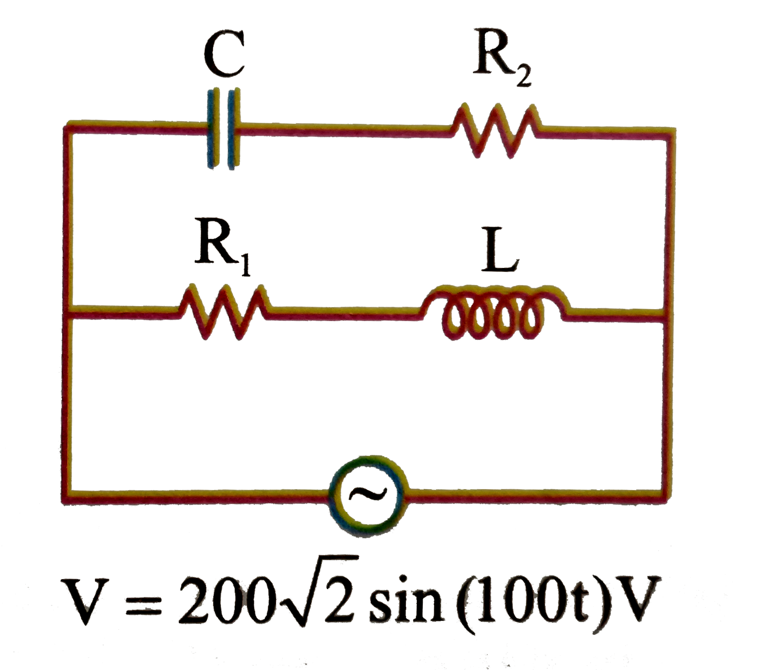
At some instant current in L−R1 circuit is 10A. At the same instant current in C−R2 branch will be
5A
5√2A
5√6A
5√3A
The correct Answer is:D
Step by step video, text & image solution for In the circuit shown in figure : R = 10 Omega , L = (sqrt(3))/(10) H, R_(2) = 20 Omega and C = (sqrt(3))/(2) mF. Current in L - R_(1) circuit is I_(1) in C - R_(1) circuit is I_(2) and the main current is I At some instant current in L - R_(1) circuit is 10 A. At the same instant current in C - R_(2) branch will be by Physics experts to help you in doubts & scoring excellent marks in Class 12 exams.
Updated on:21/07/2023Similar Questions
Knowledge Check
In the circuit shown in figure :
R=10Ω,L=√310H,R2=20Ω and C=√32mF. Current in L−R1 circuit is I1 in C−R1 circuit is I2 and the main current is I
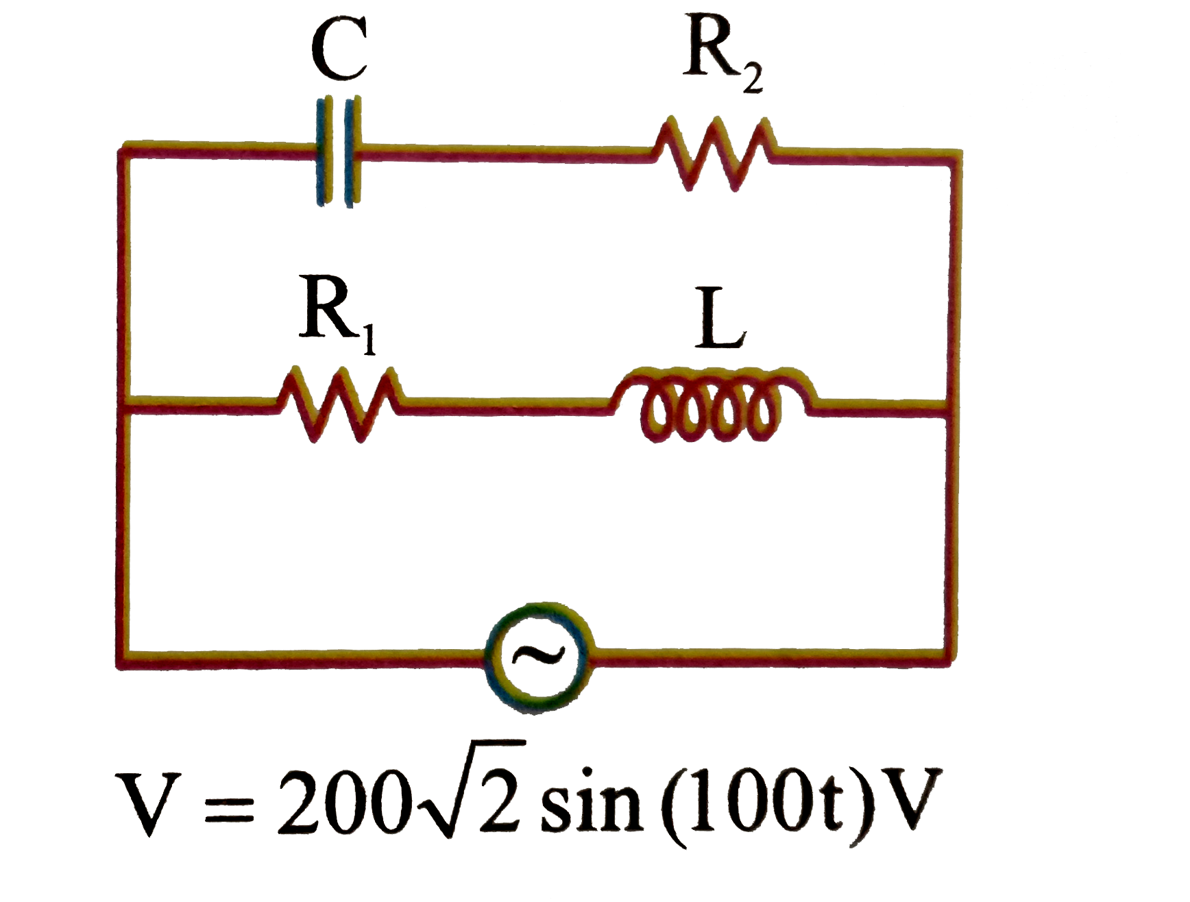
Phase difference between I1 and I2 isA0∘B90∘C180∘D60∘In the circuit shown in figure :
R=10Ω,L=√310H,R2=20Ω and C=√32mF. Current in L−R1 circuit is I1 in C−R1 circuit is I2 and the main current is I
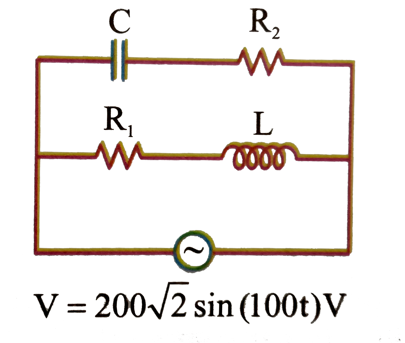
At some instant I1 in the circuit is 10√2A, then at this instant current I will beA20AB10√2AC20√2AD25AThe current in the series L-C-R circuit is
Ai=imsin(ωt+ϕ)Bi=vm√R2+(Xc−XL)2sin(ωt+ϕ)Ci=2imcos(ωt+ϕ)DBoth (a) and (b)
In the circuit shown in figure
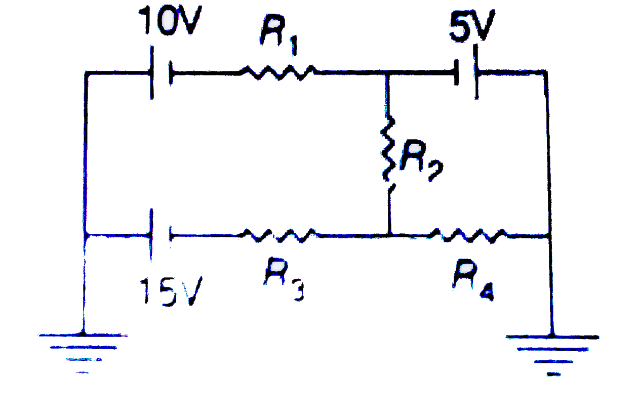
Current through R2 is zero if R4=2Ω and R3=4Ω In this case
View SolutionIf the impedance of an L-C R circuit is 40Ω, then the admitance of the circuit will be
View SolutionIn the circuit shown in fig. XC=100Ω,(XL)=200ΩandR=100Ω. The effective current through the source is
View SolutionIn the circuit shows in Fig E=15V, R1=1Ω, R2=1Ω, R3=2Ω, and L=1.5H. The currents flowing through R1,R2,and R3 are i1,i2, and i3, respectively.
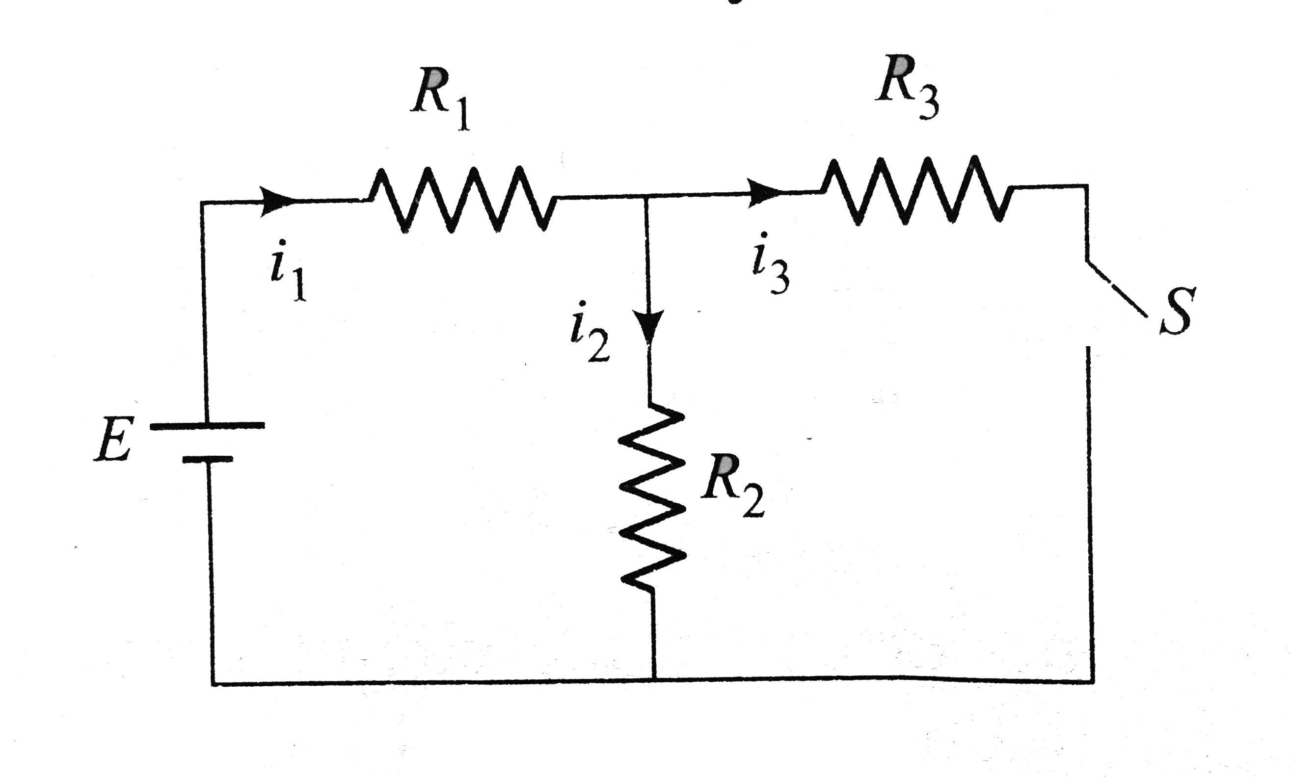
After the circuit reaches the steady state,
View SolutionAt resonance the peak value of current in L−C−R series circuit is
View Solution

