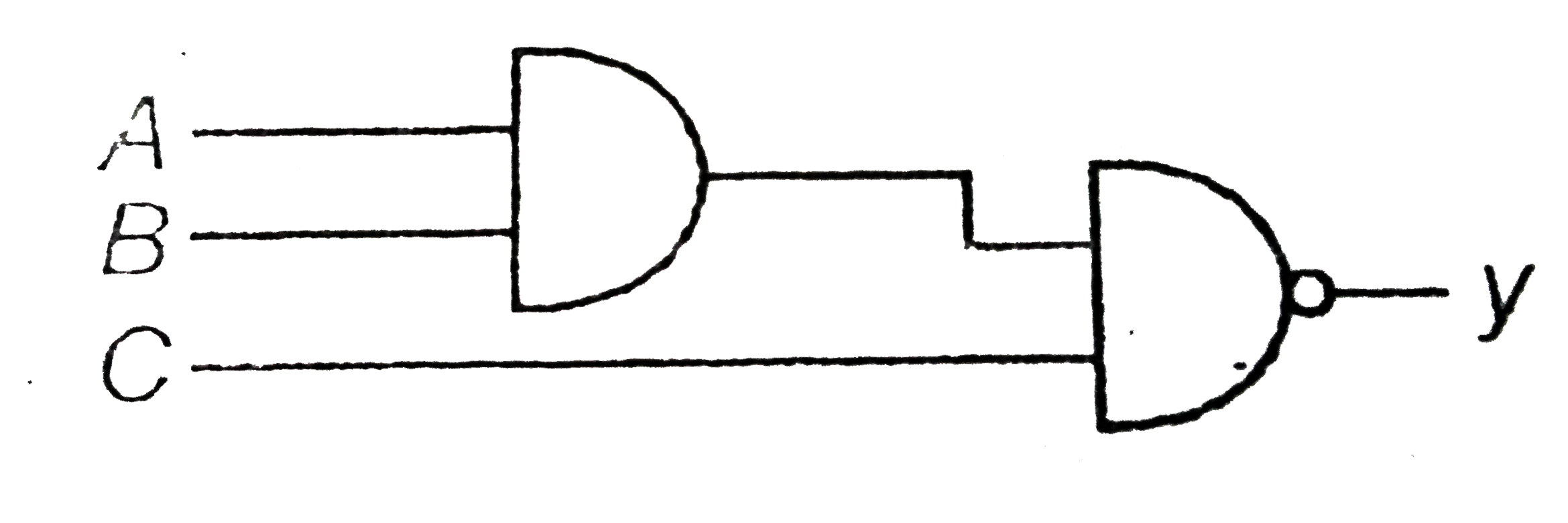
Output is LOW if and only if all the inputs are HIGH'. Indicate the logic gate for which the above statement in ture :-
AND
OR
NOR
NAND
The correct Answer is:D
Step by step video, text & image solution for Output is LOW if and only if all the inputs are HIGH'. Indicate the logic gate for which the above statement in ture :- by Physics experts to help you in doubts & scoring excellent marks in Class 12 exams.
Updated on:21/07/2023Topper's Solved these Questions
- LOGIC GATESBOOK - MOTIONCHAPTER - LOGIC GATESEXERCISE - EXERCISE - 2
10 Videos
- LOGIC GATESBOOK - MOTIONCHAPTER - LOGIC GATESEXERCISE - EXERCISE - 2
10 Videos
- KINETIC THEORY OF GASES BOOK - MOTIONCHAPTER - KINETIC THEORY OF GASES EXERCISE - EXERCISE-3 SECTION-B
16 Videos
- MAGNETISM BOOK - MOTIONCHAPTER - MAGNETISM EXERCISE - EXERCISE-4 (LEVEL-II)
40 Videos
Similar Questions
It is required to design a (two -input) logic gate, using an appropriate number, of :
(a) NAND gates that gives a 'low' output only when both the inputs are 'low'.
(b) NOR gates that gives a 'high' output only when both the inputs are 'high'.
Draw the logic circuits for these two cases and write the truth table, corresponding to each of the two designs.
View SolutionThe output A when all three inputs are first high and then low respectively, be

View Solution
Knowledge Check
A NOR gate is ON only when all its inputs are
AoffBONChighDpositiveThe output of 2 input gate is 1 only if its inputs are equal. It is true for :-
ANANDBANDCEX-NORDEX-ORThe gate for which output is high, if atleast one input low is
ANANDBNORCANDDOR
Write the output waveform of the OR gate for the inputs
View Solution
The output y, when all three inputs are first high and then low, will respectively be
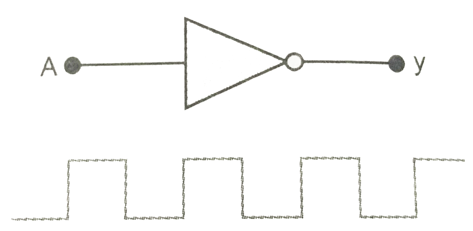
View SolutionIn Fig., circuit of a logic gate and input waveform is shown. (i) Name the logic gate (ii) Write its truth table and (iii) give the output wavefrom.

View SolutionThe output of an OR gate is connected to both the input of a NAND gate. Draw the logic circuit of this combination of gates and write its truth tablr.
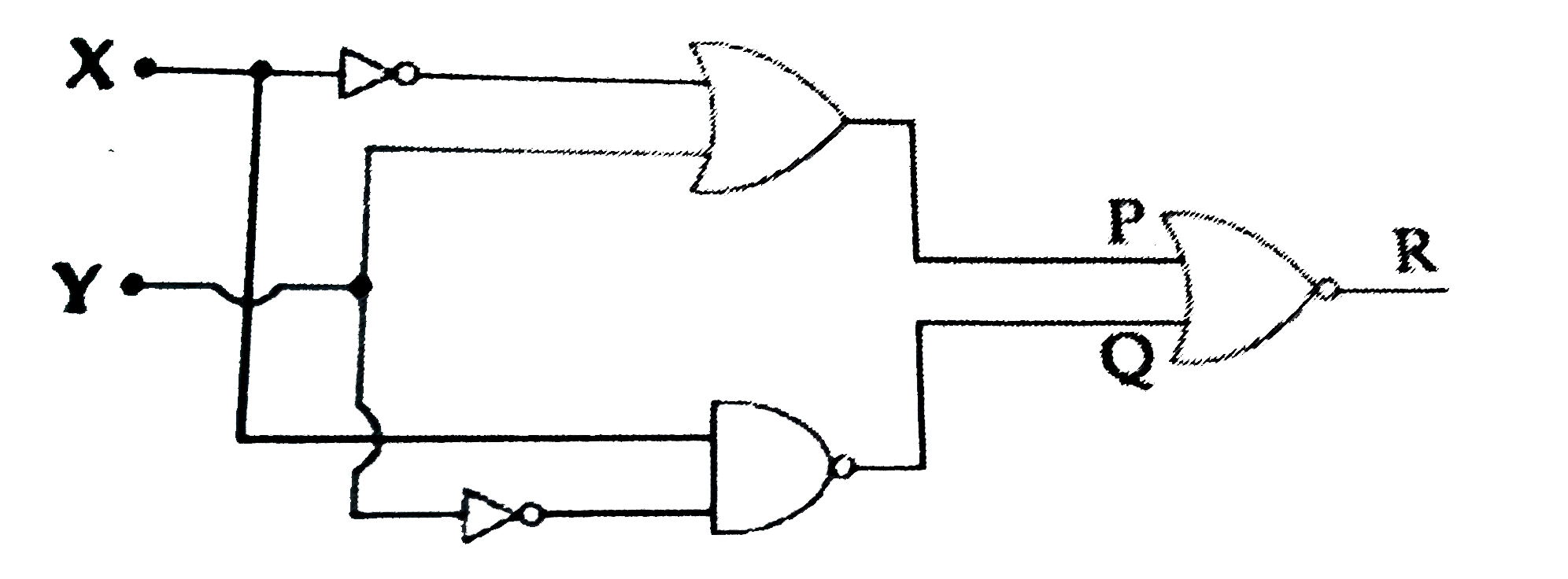
View SolutionTo get output '1' at R, for the given logic gate circuit the input values must be :

View Solution
