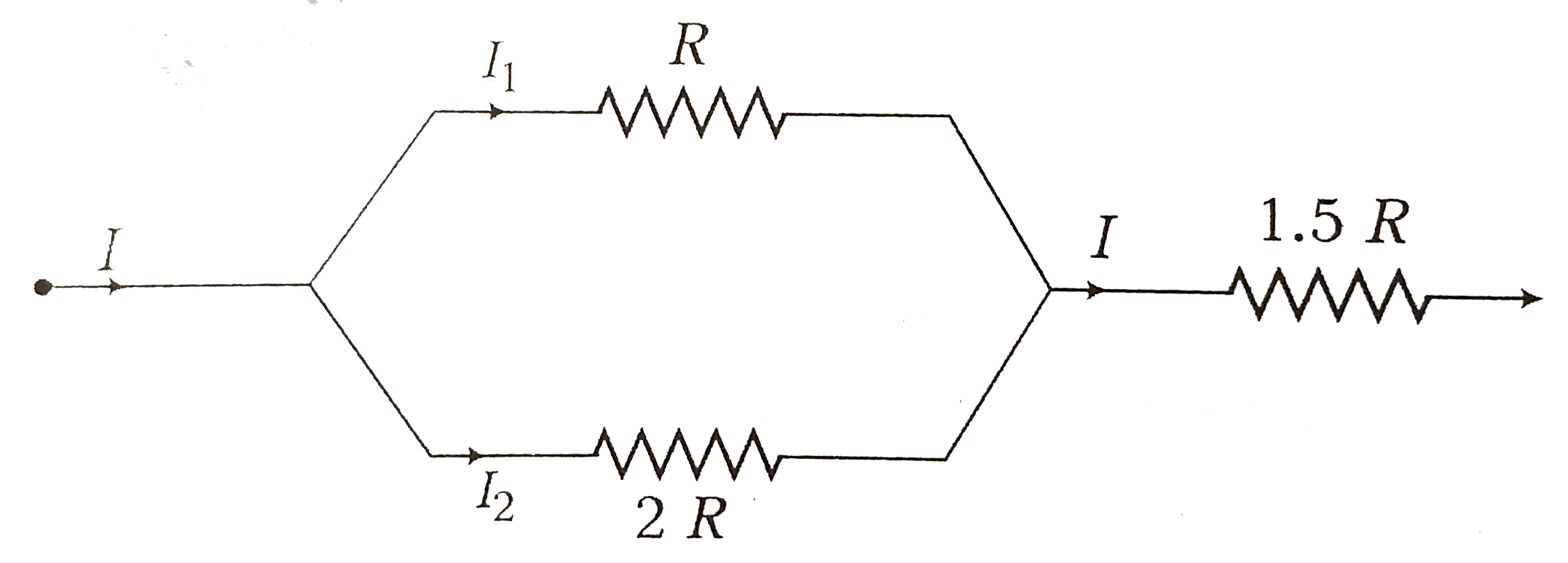
In the circuit diagram,heat produces in R, 2R and 1.5R are in the ratio of
4:2:3
8:4:27
2:4:3
27:8:4
The correct Answer is:B
Step by step video, text & image solution for In the circuit diagram,heat produces in R, 2R and 1.5 R are in the ratio of by Physics experts to help you in doubts & scoring excellent marks in Class 12 exams.
Updated on:21/07/2023Topper's Solved these Questions
- CURRENT ELECTRICITYBOOK - DC PANDEYCHAPTER - CURRENT ELECTRICITYEXERCISE - Match the columns
4 Videos
- COMMUNICATION SYSTEMBOOK - DC PANDEYCHAPTER - COMMUNICATION SYSTEMEXERCISE - Subjective
11 Videos
- ELECTROMAGNETIC INDUCTIONBOOK - DC PANDEYCHAPTER - ELECTROMAGNETIC INDUCTIONEXERCISE - Medical entrances gallery
25 Videos
Similar Questions
Knowledge Check
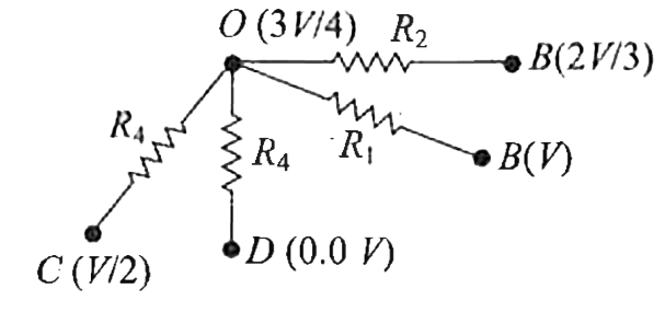
The circuit is shown in the following figure. The potential at points A, B, C, D and O are given. The currents in the resistance R1,R2 and R3 are in the ratio of 4:2:1. What is the ratio of resistance R1,R2,R3 and R4 ?
 A3:2:12:16B2:3:36:12C4:3:12:32D3:4:14:32
Three resistors R1,R2 and R3 are to be combined to form an electrical circuit as shown in the figure. It is found that when R1R2andR3 are put respectively in positions A, B and C, the effective resistance of the circuit is 70 ΩWhen R2,R3andR1 are put respectively in position A, B and C the effective resistance is 35Ω and when R3,R1andR2 are respectively put in the position A, B and C, the effective resistance is 42Ω
The resistanceR1:R2:R3are in the ratioA0.04380787037037B0.043101851851852C0.043854166666667D0.043819444444444A battery of emf E and internal resistance r is connected to a resistor of restance r1 and Q Joules of heat is produced in a certain time t. When te same battery is connected to another resistor of resistance r2 the same quantity of heat is produced in the same time t. Then the value of r is
Ar21r2Br22r1C12(r1+r2)D√r1r2
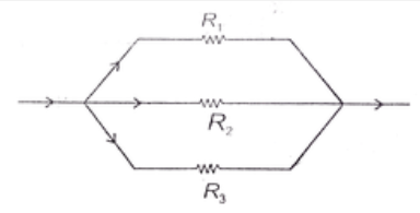
In the situation shown, resistance R1,R2 and R3 are in the ratio 3:2:1 , then
View SolutionIn the circuit diagram given below, three resistors R1,R2, and R3 of 5Ω,10Ω and 30Ω, respectively are connected as shown.
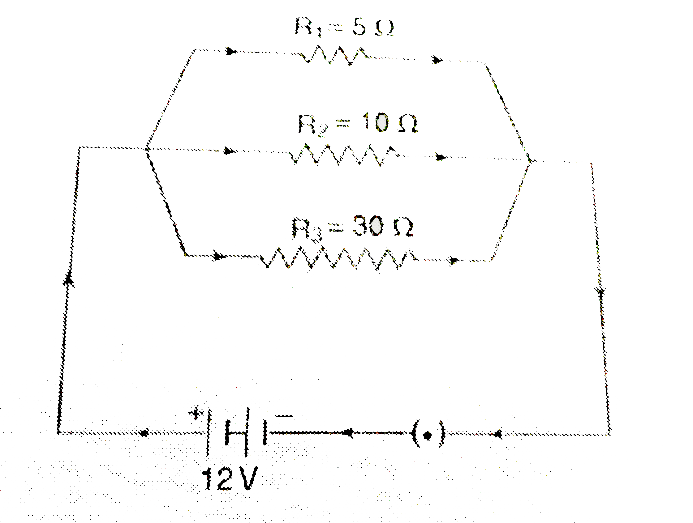
Calculate:
(a) current through each resistor.
(b) total current in the circuit.
(c) total resistance in the circuit.
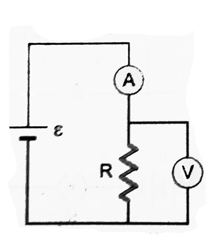
View SolutionA voltmeter of resistance RV and an ammeter of resistance RA are connected in a circuit to measure a resistance R as shown in figure. The ratio of the meter readings gives an apparent resistance R′. Show that R and R′ are related by the relation
1R=1R′−1RV
View SolutionThree resistors R1,R2 and R3 are to be combined to form an electrical circuit as shown in the figure. It is found that when R1R2andR3 are put respectively in positions A, B and C, the effective resistance of the circuit is 70 ΩWhen R2,R3andR1 are put respectively in position A, B and C the effective resistance is 35Ω and when R3,R1andR2 are respectively put in the position A, B and C, the effective resistance is 42Ω
IfR_(1), R_(2)and R,_(3)are put in series, the effective resistance will be
View SolutionThree resistors R1,R2 and R3 are to be combined to form an electrical circuit as shown in the figure. It is found that when R1R2andR3 are put respectively in positions A, B and C, the effective resistance of the circuit is 70 ΩWhen R2,R3andR1 are put respectively in position A, B and C the effective resistance is 35Ω and when R3,R1andR2 are respectively put in the position A, B and C, the effective resistance is 42Ω
If R1,R2andR3 are all connected in parallel, the effective resistance will be
View Solution
