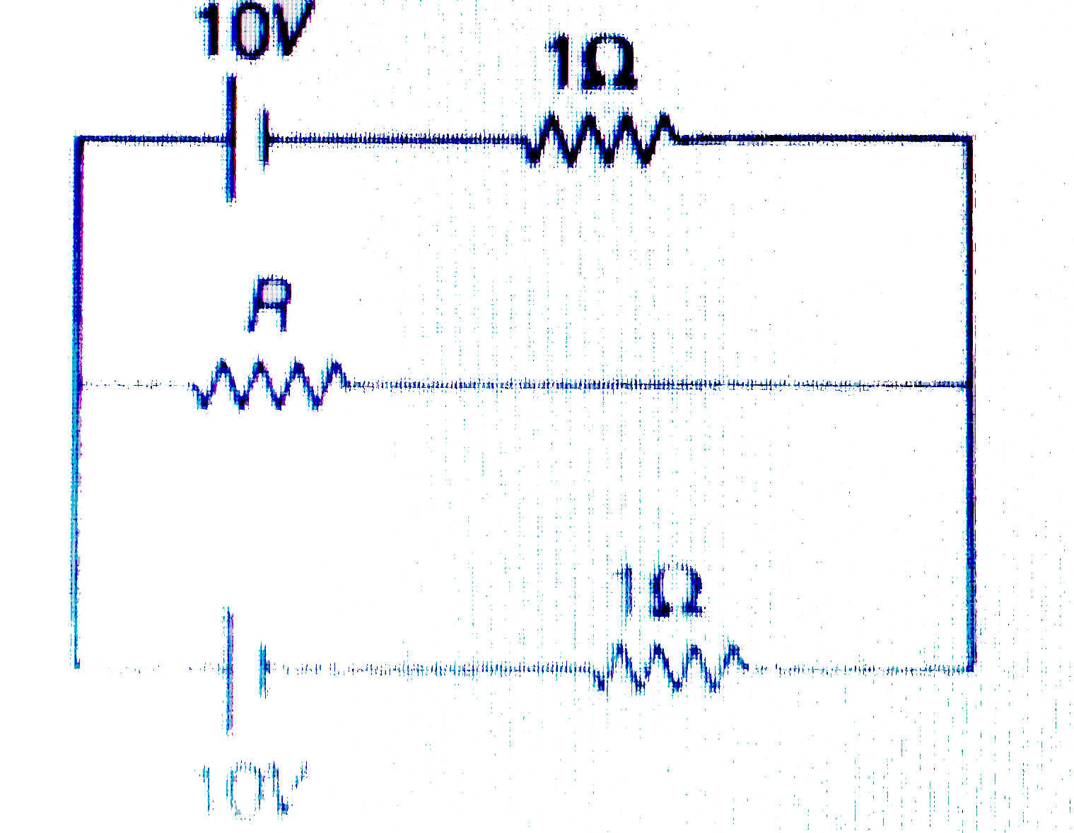
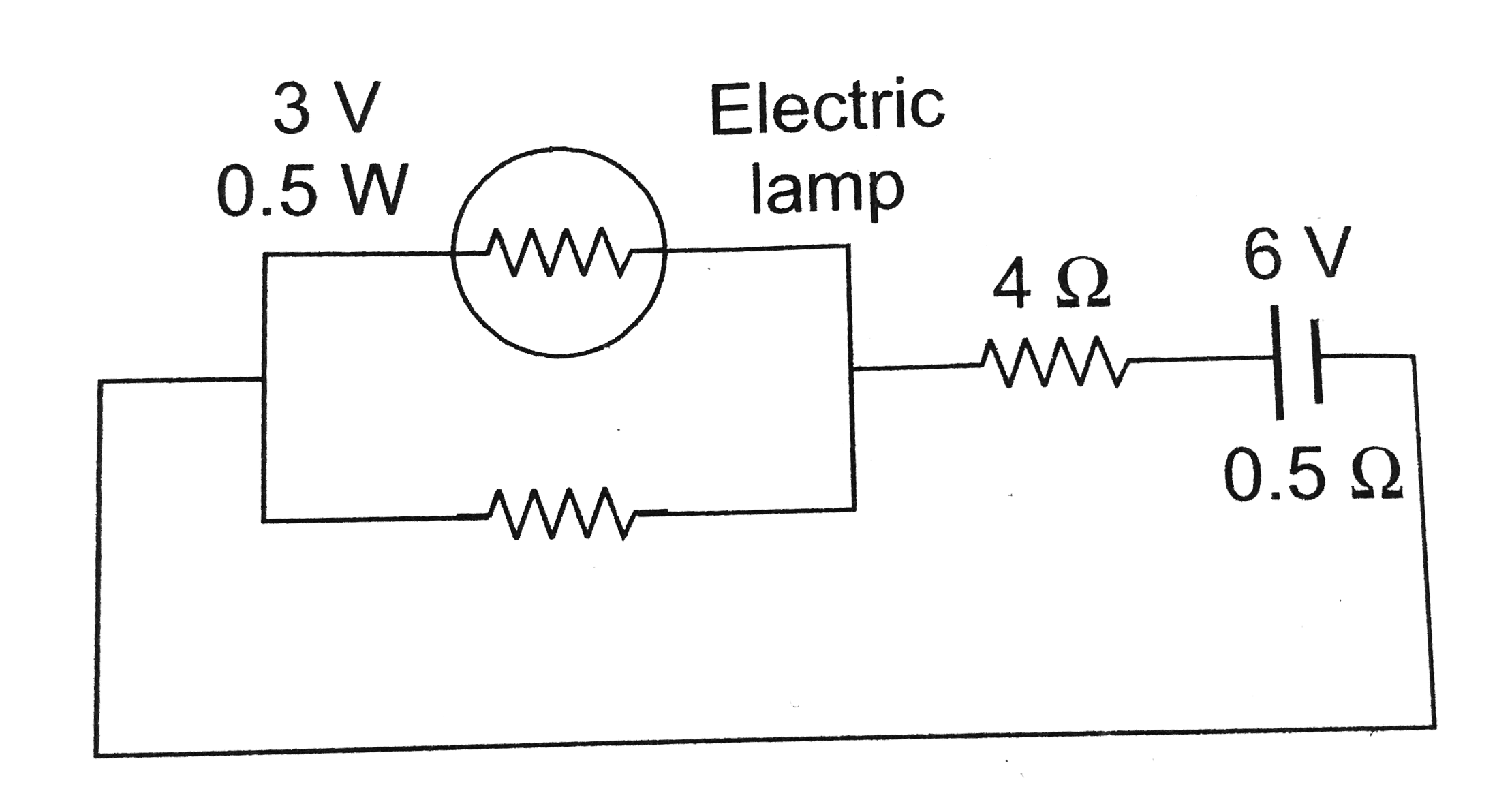
Maximum power developed across variable resistance R in the circuit shown in figure is
A
50 W
B
75 W
C
25 W
D
100 W
Video Solution
Text Solution
The correct Answer is:A
|
Answer
Step by step video, text & image solution for Maximum power developed across variable resistance R in the circuit shown in figure is by Physics experts to help you in doubts & scoring excellent marks in Class 11 exams.
Updated on:21/07/2023Topper's Solved these Questions
Similar Questions
Knowledge Check
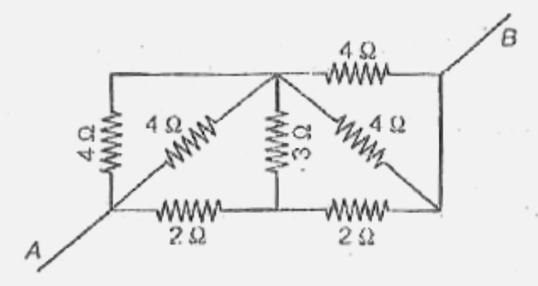
The equivalent resistance of the circuit shown in the figure is
 A8ΩB6ΩC5ΩD4Ω
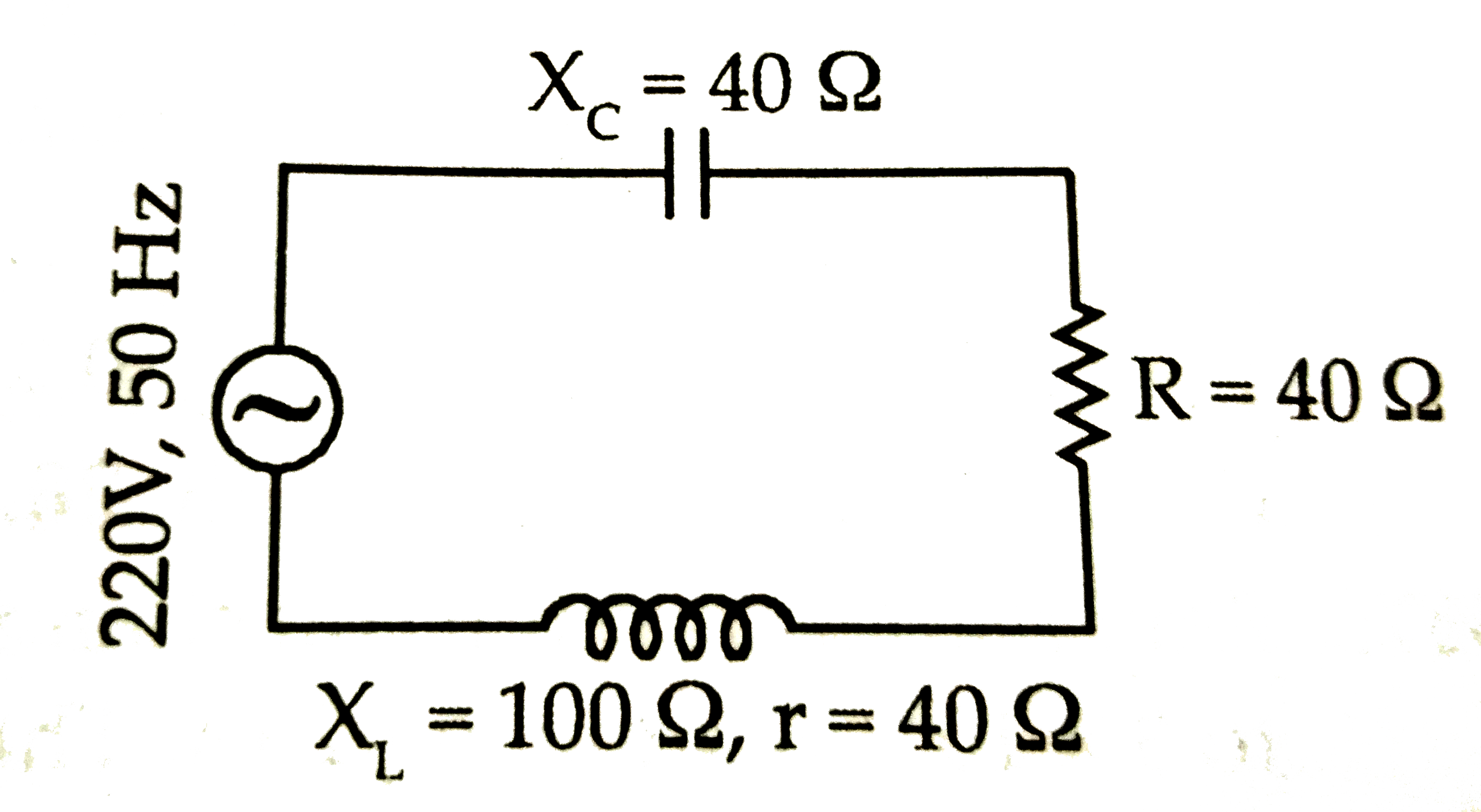
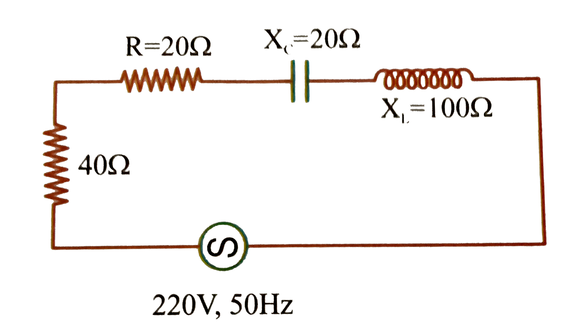
The power factor of the circuit shown in the figure is
 A0.4B0.2C0.8D0.6
The power factor of the circuit as shown in figure is
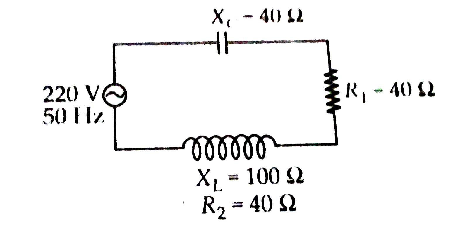 A0.2B0.4C0.8D0.6
Resistance across AB as shown in figure is
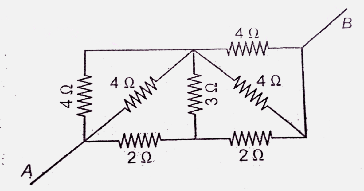
View SolutionPotential difference across AB in the circuit as shown in figure.

View Solution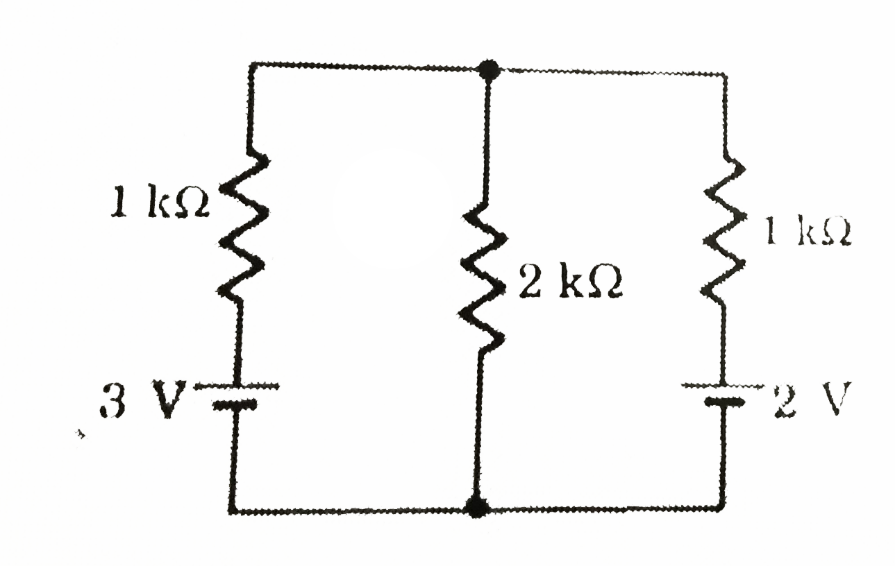
Calculate the potential difference across the 2k Ω resistor in the circuit shown in figure. The internal resistance of the cells are negligible.
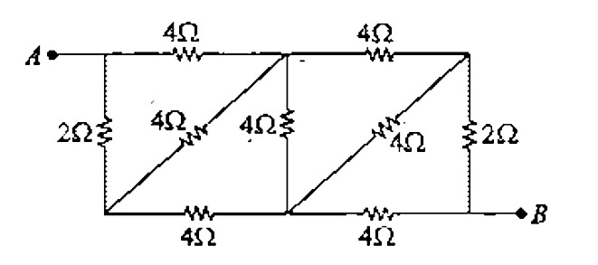
View SolutionFind the equivalent resistance across terminals A and B in the circuit shown in figure - 3.96.
[409Ω]
View SolutionWhat should be the value of resistance R in the circuit shown in figure so that the electric bulb consumes the rated power?
View Solution

