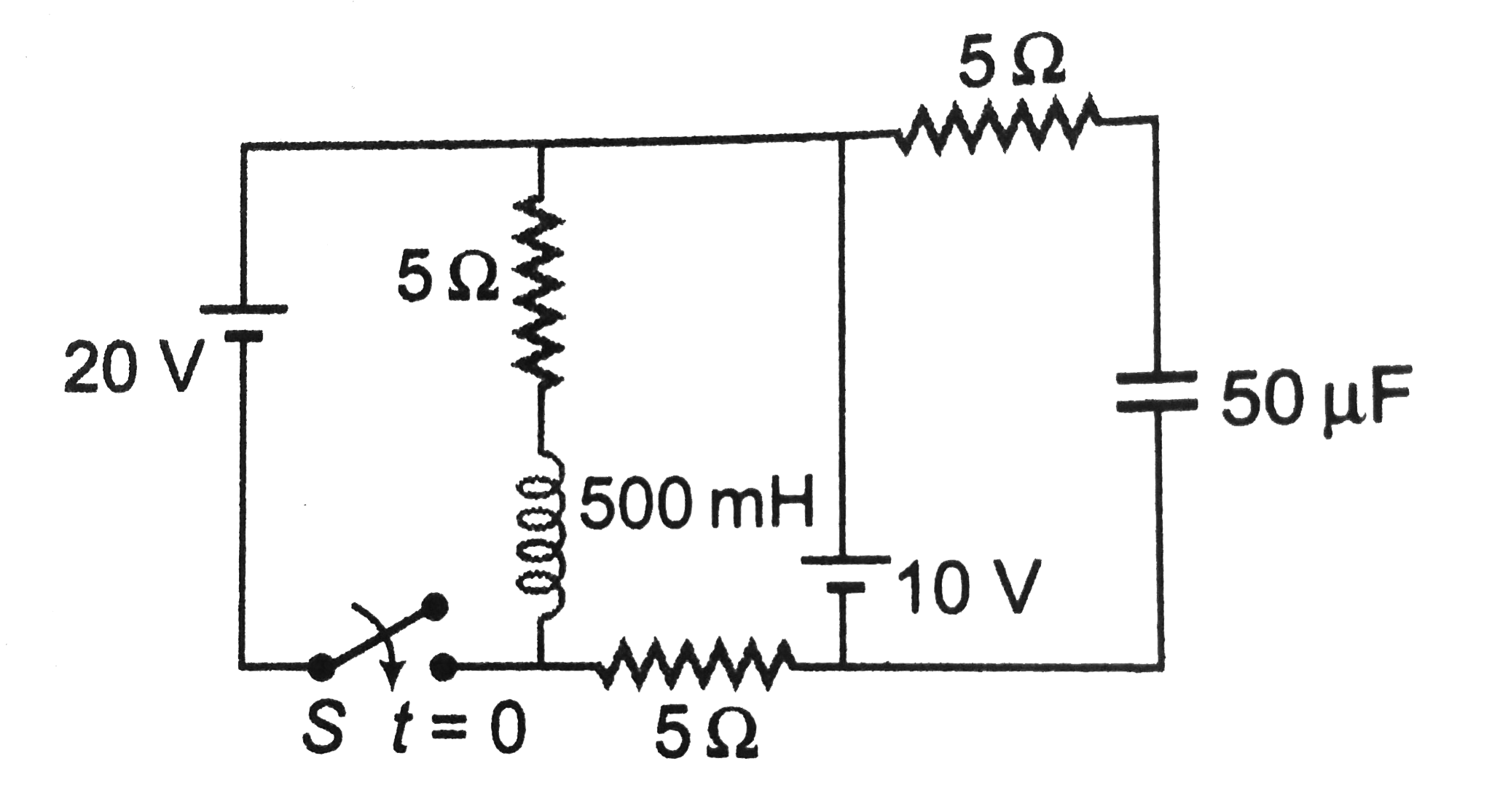
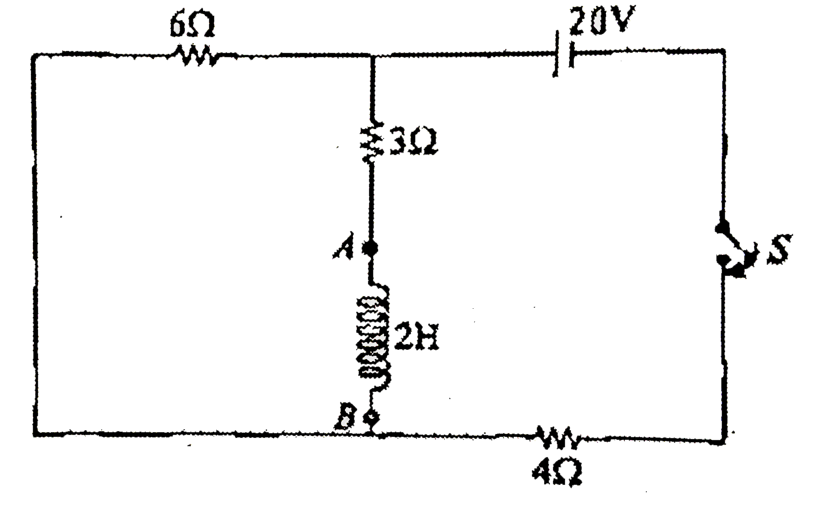
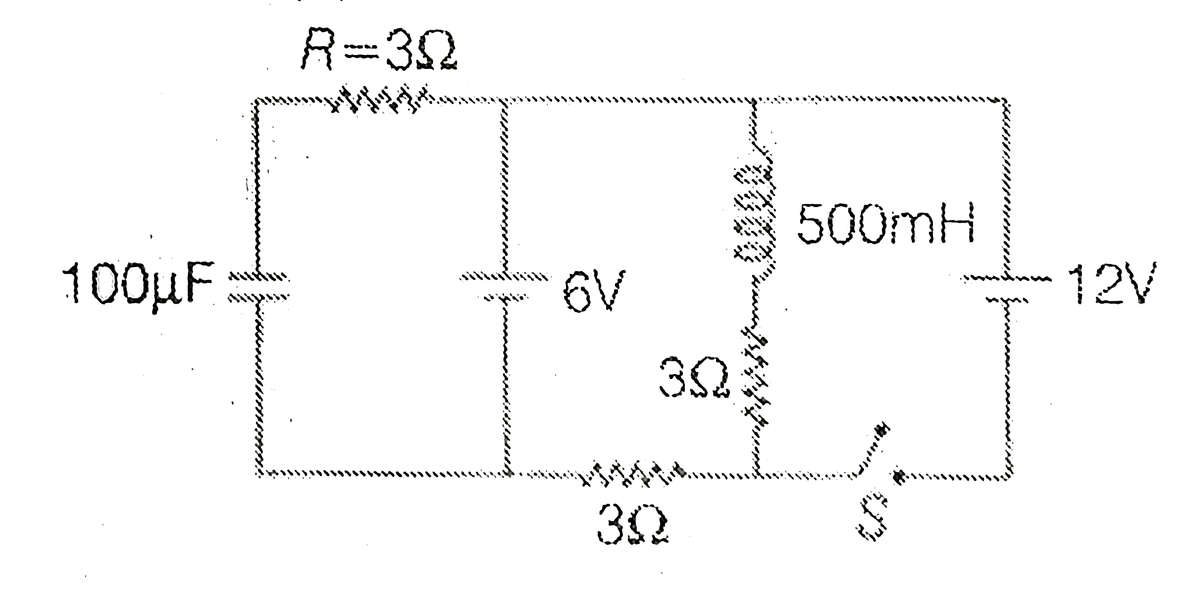
Switch S is closed t=0, in the circuit shown. The change in flux in the inductor (L=500mH) from t=0 to an instant when it reaches steady state is
2Wb
1.5Wb
0Wb
None of the above
The correct Answer is:A
Step by step video, text & image solution for Switch S is closed t=0, in the circuit shown. The change in flux in the inductor (L=500mH) from t=0 to an instant when it reaches steady state is by Physics experts to help you in doubts & scoring excellent marks in Class 12 exams.
Updated on:21/07/2023Topper's Solved these Questions
- ELECTROMAGNETIC INDUCTION AND ALTERNATING CURRENTBOOK - PHYSICS GALAXY - ASHISH ARORACHAPTER - ELECTROMAGNETIC INDUCTION AND ALTERNATING CURRENTEXERCISE - Advance MCQs
33 Videos
- ELECTROMAGNETIC INDUCTION AND ALTERNATING CURRENTBOOK - PHYSICS GALAXY - ASHISH ARORACHAPTER - ELECTROMAGNETIC INDUCTION AND ALTERNATING CURRENTEXERCISE - Conceptual MCQs
63 Videos
- CURRENT ELECTRICITYBOOK - PHYSICS GALAXY - ASHISH ARORACHAPTER - CURRENT ELECTRICITYEXERCISE - All Questions
389 Videos
- ELECTROSTATICSBOOK - PHYSICS GALAXY - ASHISH ARORACHAPTER - ELECTROSTATICSEXERCISE - Unsolved Numberical Problems
73 Videos
Similar Questions
Knowledge Check
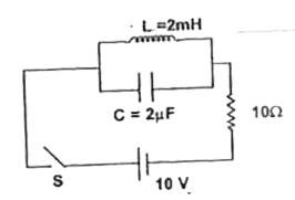
The switch S is closed in the circuit shown at time t=0 . The current in the resistor at t=0 and t=∞ are respectively .
 A0,0 AB1,0 AC0,1 AD1,1 A
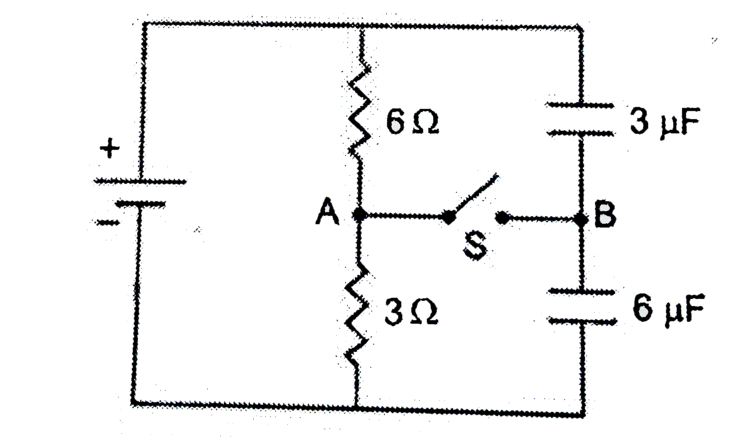
In the circuit shown above, when then switch S is closed,Ano charge flows through SBcharge flows from A to BCcharge flows from B to ADcharge flows initially from A to B and later from B to AIn the circuit shows in Fig the switch is closed at t=0.
 AAt t=0,I1=I2=0BAt any time t,I0I2=L2L1CAt any time t, I1+I2=εRDAt t=∞,I1 and I2 are independent of L1 and L2
In the circuit shown in figure-5.115, find the current in inductor as a function of time if switch is closed at t=0.
View SolutionIn the circuit as shown in figure the switch is closed at t=0.
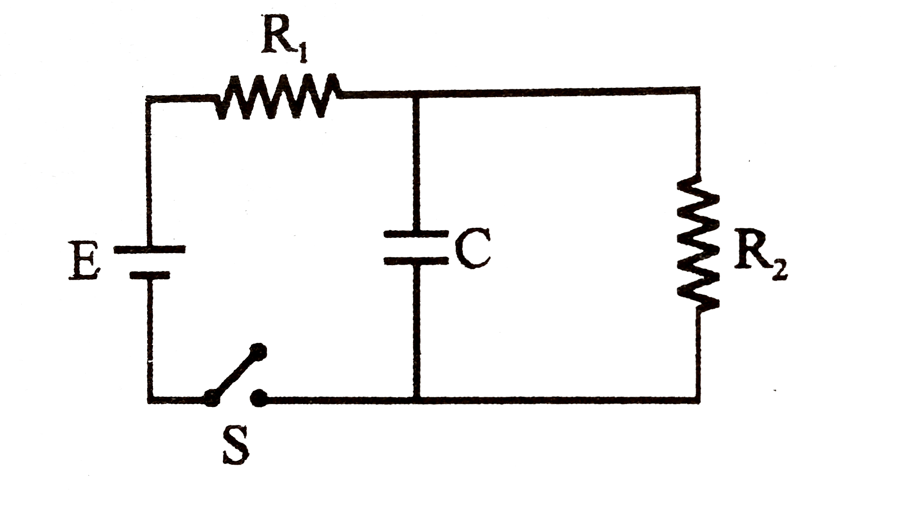
At the instant of closing the switch
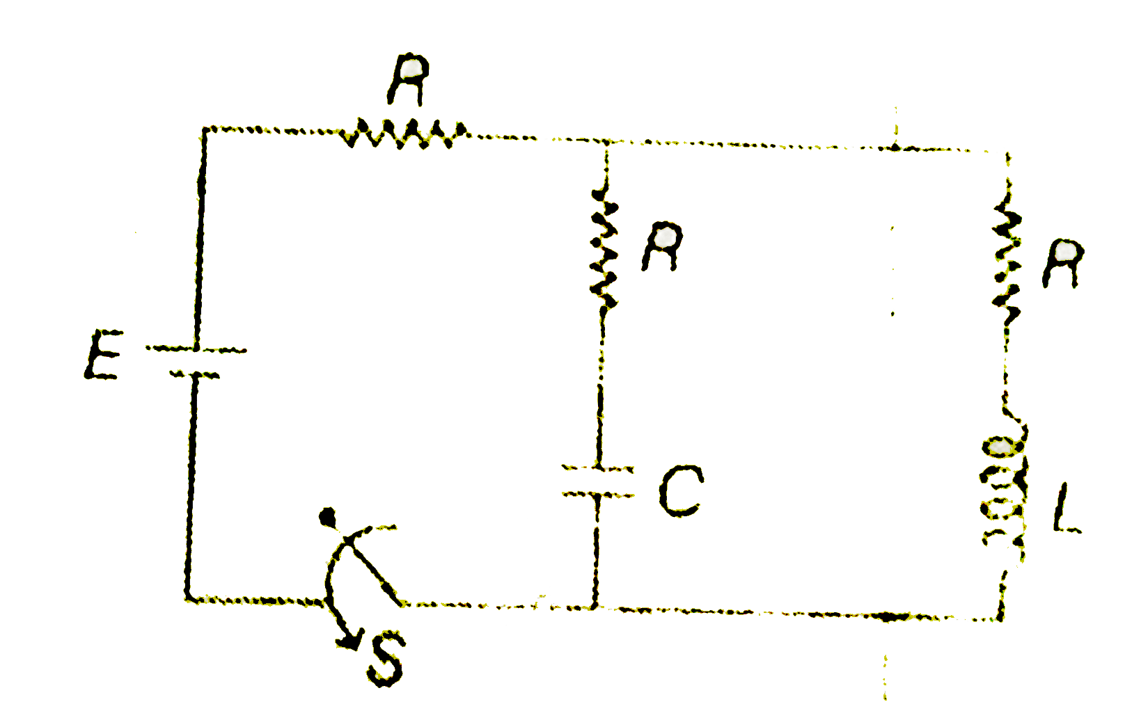
View SolutionIn the circuit as shown in the figure, switch S is added at t=0. Then:
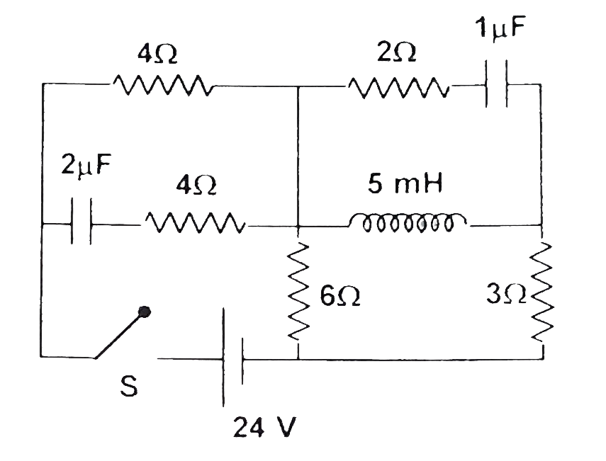
View SolutionIn the circuit shown, the switch 'S' is closed at t=0. Then the current through the battery steady state reached is
View SolutionIn the circuit diagram shown in figure, initially switch S is opened and the circuit is in steady state. At time t=0, the switch S is closed and the new steady state is reached after some time. Choose the correct option(s)
View Solution

_PHY_E06_157_Q01.png)
