In the given LC circuit if initially capacitor C has change Q on it and 2C has charge 2Q. The polarities are as shown in the figure. Then after closing the switch s at t=0
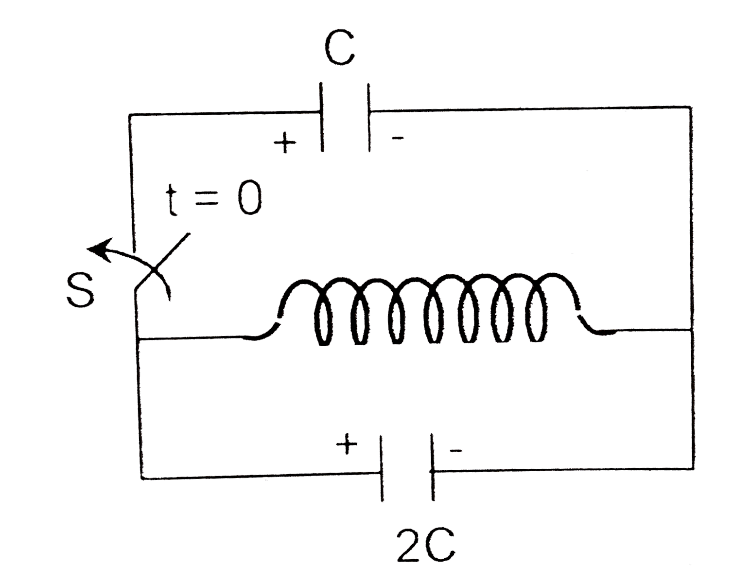
Energy will get equally distributed in both the capcitor just after closing the switch.
Initial rate of growth of current in inductor is 2Q/3CL
Maximumum energy in the inductor will be 4Q2/3C
None of these
The correct Answer is:D
Step by step video, text & image solution for In the given LC circuit if initially capacitor C has change Q on it and 2C has charge 2Q. The polarities are as shown in the figure. Then after closing the switch s at t = 0 by Physics experts to help you in doubts & scoring excellent marks in Class 12 exams.
Updated on:21/07/2023Topper's Solved these Questions
- ELECTROMAGNETIC INDUCTION AND ALTERNATING CURRENTBook:PHYSICS GALAXY - ASHISH ARORAChapter:ELECTROMAGNETIC INDUCTION AND ALTERNATING CURRENTExercise:Numerical MCQs
Explore 60 Videos
- ELECTROMAGNETIC INDUCTION AND ALTERNATING CURRENTBook:PHYSICS GALAXY - ASHISH ARORAChapter:ELECTROMAGNETIC INDUCTION AND ALTERNATING CURRENTExercise:Advance MCQs
Explore 33 Videos
- ELECTROMAGNETIC INDUCTION AND ALTERNATING CURRENTBook:PHYSICS GALAXY - ASHISH ARORAChapter:ELECTROMAGNETIC INDUCTION AND ALTERNATING CURRENTExercise:Discussion Question-
Explore 21 Videos
- CURRENT ELECTRICITYBook:PHYSICS GALAXY - ASHISH ARORAChapter:CURRENT ELECTRICITYExercise:All Questions
Explore 389 Videos
- ELECTROSTATICSBook:PHYSICS GALAXY - ASHISH ARORAChapter:ELECTROSTATICSExercise:Unsolved Numberical Problems
Explore 73 Videos
Similar Questions
Knowledge Check
In the given LC circuit,if initially capacitor C has charge Q on it and 2C has charge 2Q. The polar ar as shown in figure. Then after closing switch S and t=0
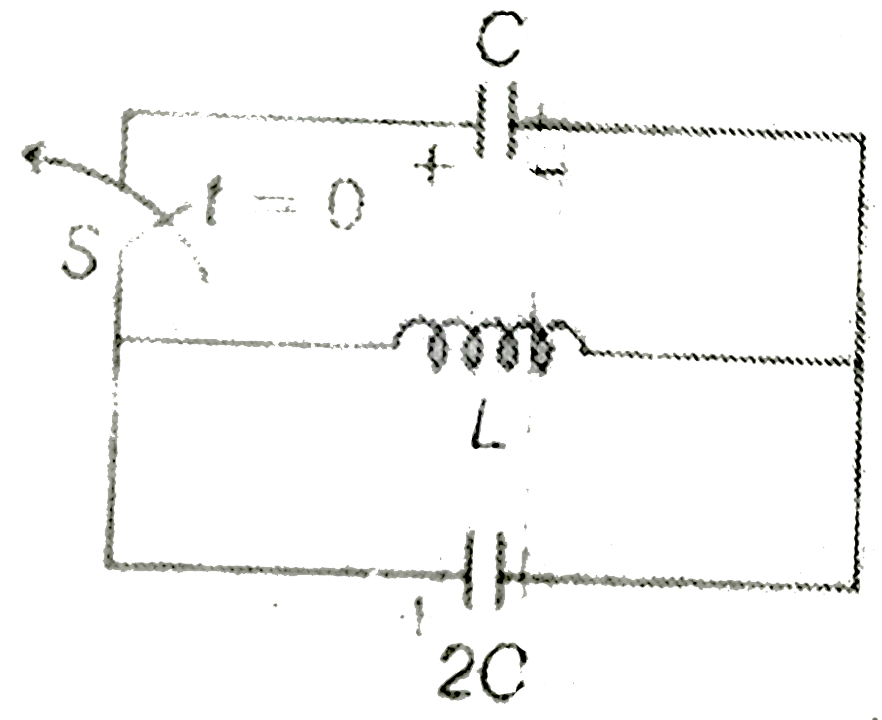 Aenergy will get equally distributed in both the capacitors ust after closing the switchBinitial rate of groqth of current in inductor will be 2Q/3CLCmaximum energy in the inductor will be 3Q2/2CDnone of these
In the given figure switch is open initially and capacitor C2 is unchanged
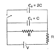
Charge on C2 just after closing the switch isACV2BCV3CCV4DCV8In the given circuit, the initial charges on the capacitors are shown in the figure. The charge flown through the switches S1andS2 respectively after closing the switches are
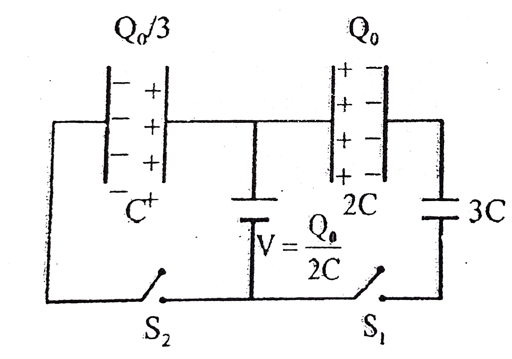 AzeroQ06BQ05,Q02Czero,Q02D35Q0,Q06
In the circuit shown in figure-3.345 the capacitor of capacitance C is charged to a potential difference V. The current in the circuit just after the closing of switch S is :
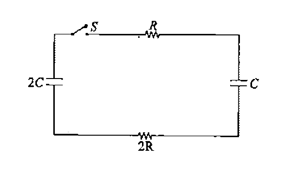
View SolutionIn the given figure switch is open initially and capacitor C2 is unchanged
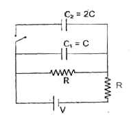
Potential difference on C1just after closing the switch is
View SolutionIn the circuit shown initially C1,C2 are uncharged. After closing the switch
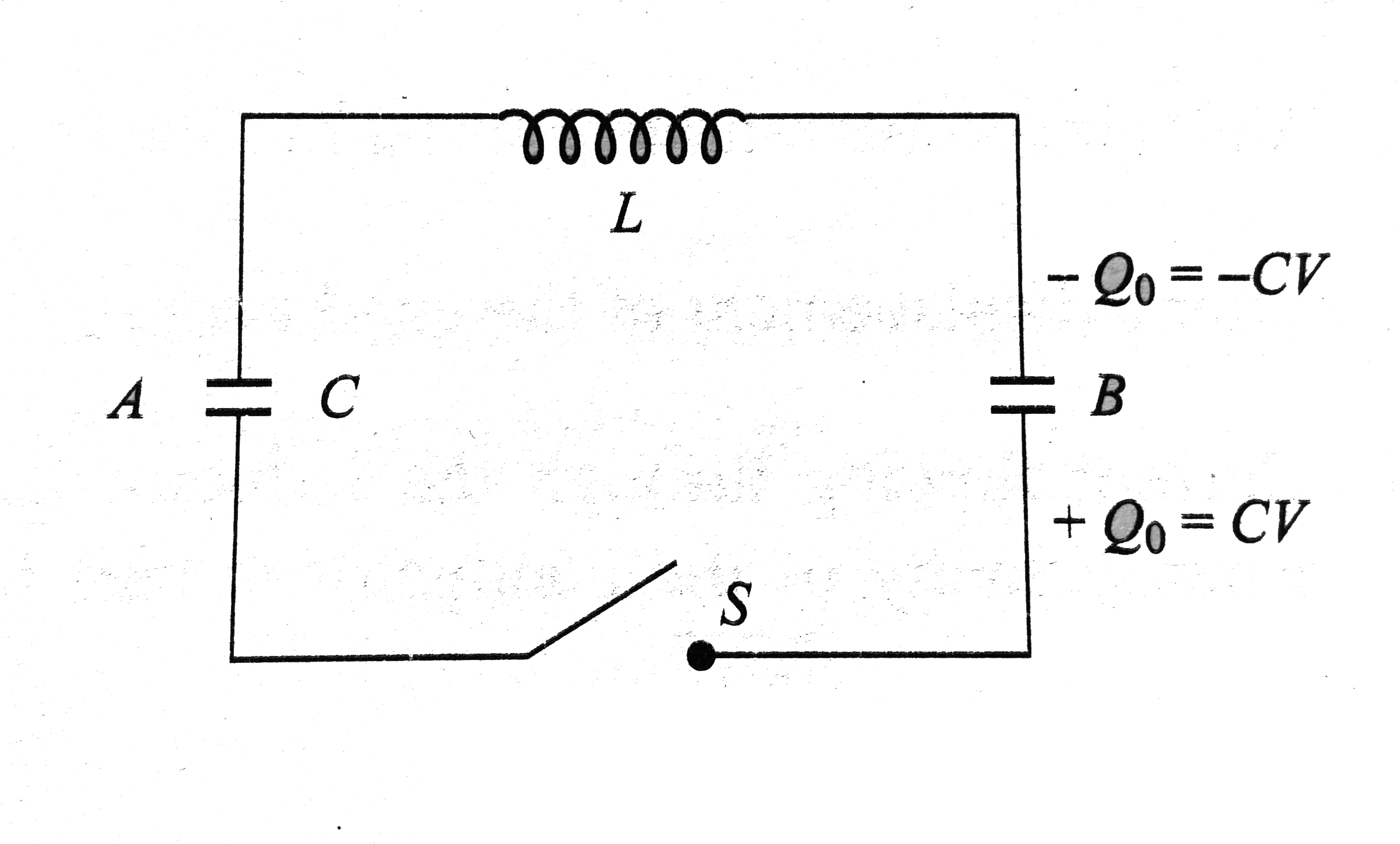
View SolutionAn inductor and two capacitors are connected in the circuit as show in Fig Initially capacitor A has no charge and capacitor B has CV charge. Assume that the circuit has no resistance at all. At t=0, switch S is closed, then [given
LC=2π2×10⁴S2 and Cv=100mC]
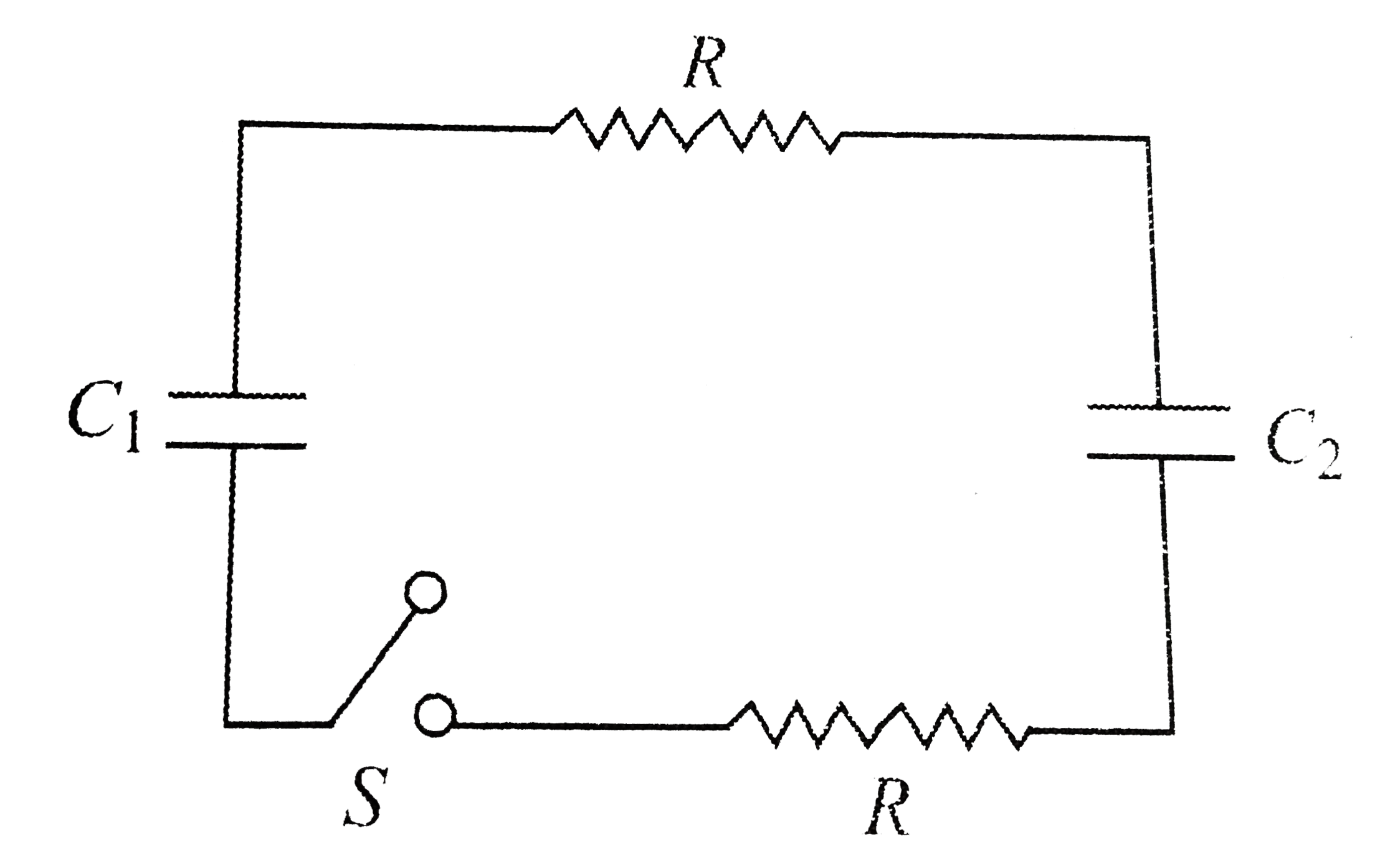
View SolutionIn the circuit shown in fig. C1=2C2 Initially, capacitor C1 is charged to a potential of V. The current in the circuit just after the switch S is closed is
View Solution


