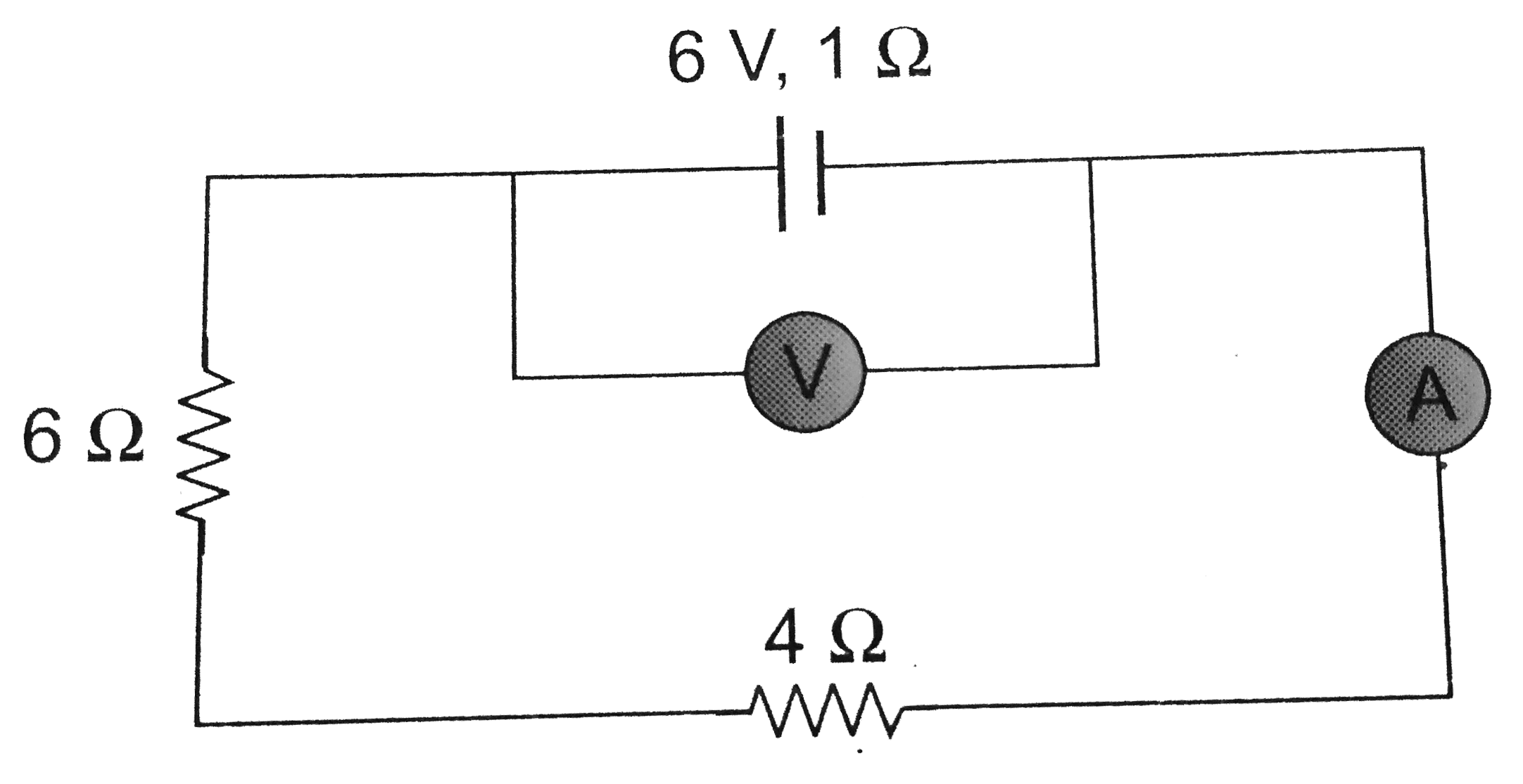
In the circuit shown in figure ammeter and voltmeter are ideal. If and then readings of ammeter and voltmeter are
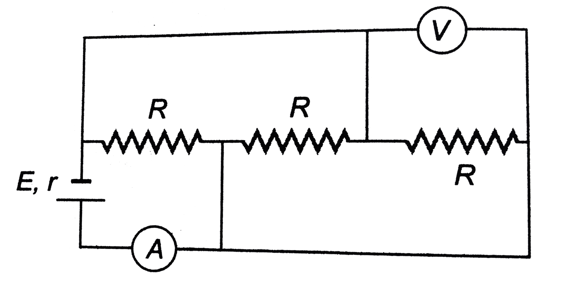
1A,3V
2A,3V
3A,4V
4A,4V
The correct Answer is:D
Step by step video, text & image solution for In the circuit shown in figure ammeter and voltmeter are ideal. If E=4 V,R=9Omega and r=1Omega then readings of ammeter and voltmeter are by Physics experts to help you in doubts & scoring excellent marks in Class 12 exams.
Updated on:21/07/2023Topper's Solved these Questions
Similar Questions
Knowledge Check
In the circuit shwon in figure, ammeter and voltmeter are ideal. E=4V,R=15Ω and r=1Ω, then reading of ammter (in A) and voltmeter (in V) respectively are:
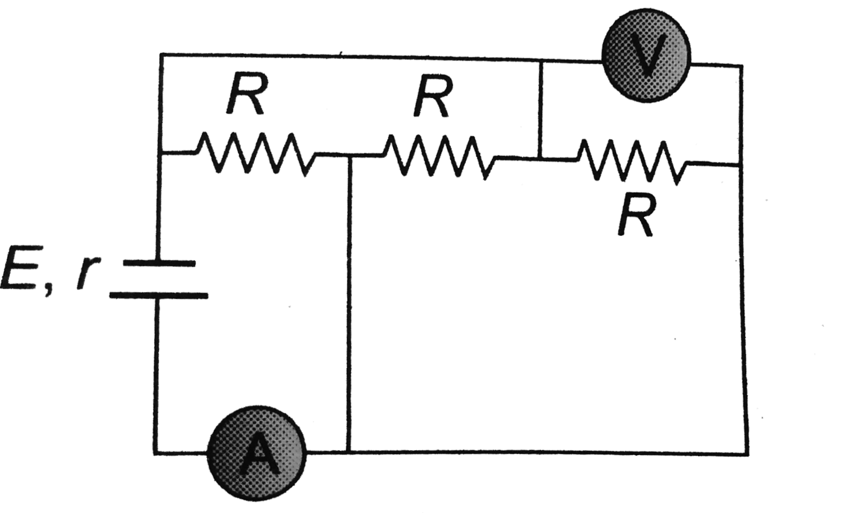 A2/3,11/3B2/3,10/3C10/3,2/3Dnone of these
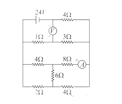
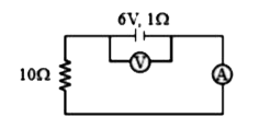
In the circuit shown here, the readings of the ammeter and voltmeter are
 A6A,60VB0.6A,6VC6/11A,60/11VD11/6A,11/60V
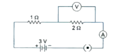
Find the readings of the ammeter (A) and voltmeter (V):
 A6 A, 60 VB0.6A, 6VC6A, 6VD611A,6011V
In the circuit shown in figure,an ideal ammeter and an ideal voltmeter are used.When the key is open,the voltmeter reads "1.53V".When the key is ,the ammeter reads "1.0A" and the voltmeter reads "1.03V" .The resistance "R" is
View Solution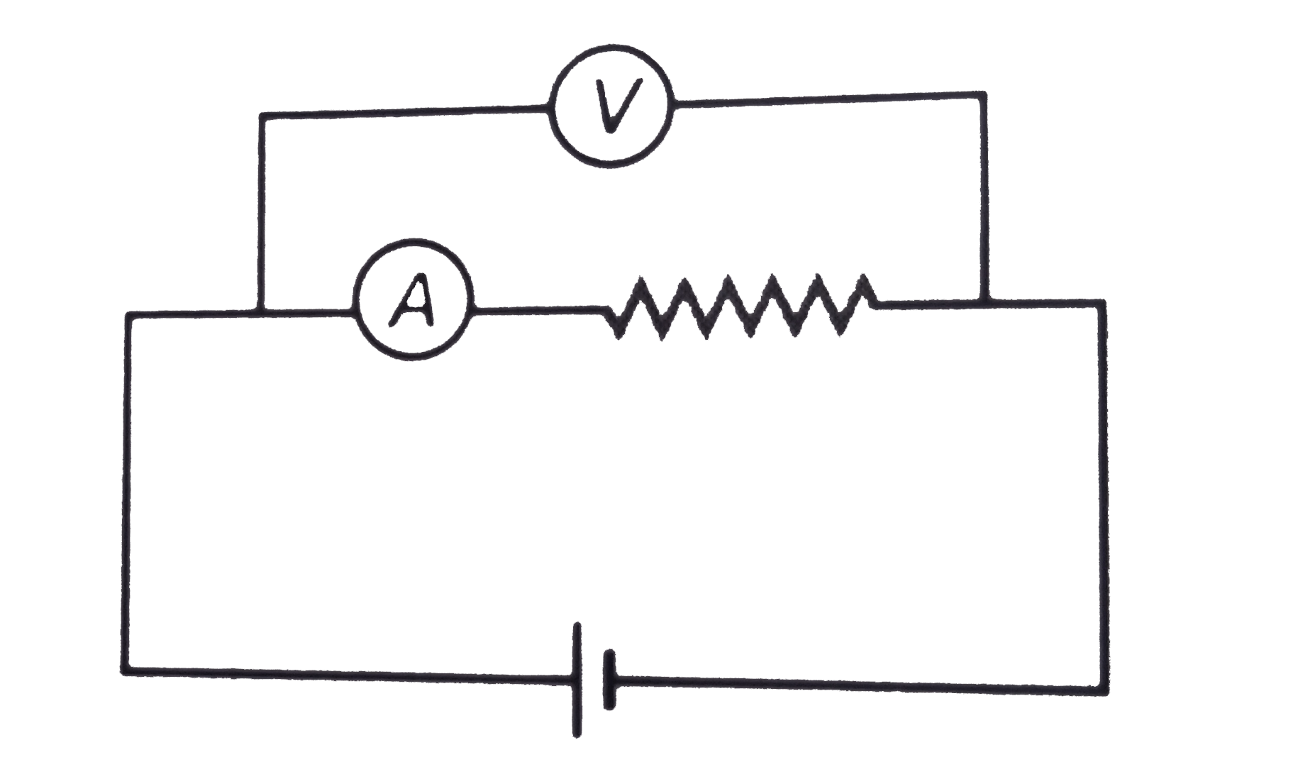
Assertion : In the circuit shown in figure ammeter and voltmeter are non-ideal. Why positions of ammeter and voltmeter are changed, reading of ammeter will increase while of voltmeter will decrease.
Reason : Resistance of an ideal ammeter is zero while that of an ideal voltmeter is infinite.
View Solution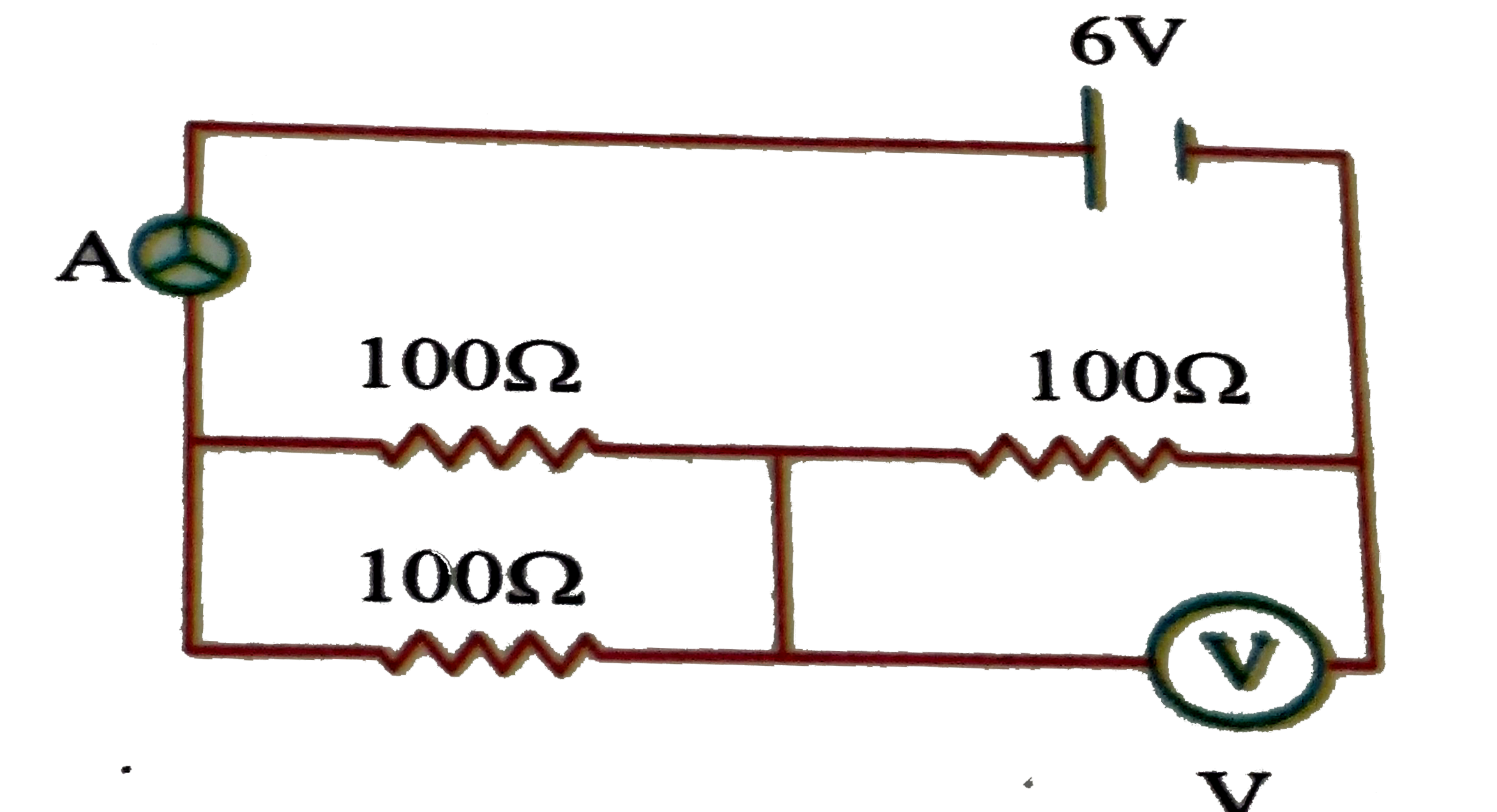
In the circuit shown, the reading of the voltmeter and the ammeter are
View SolutionIn the circuit shown in figure, what will be the readings of voltmeter and ammeter?
View SolutionIn the circuit shown, A and V are ideal ammeter and voltmeter respectively. Reading of the voltmeter will be

View Solution

